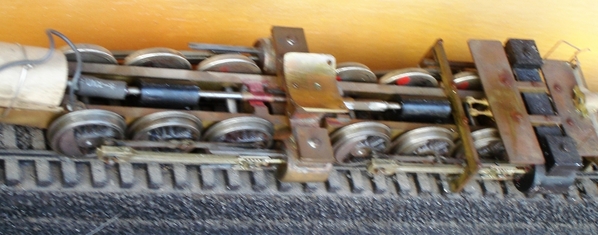
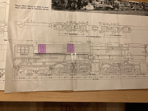
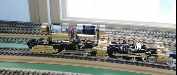
I read posts about people doing work to other brands of engines. I have the Challenger and it's motor and gears are very loud. Our grandson says the UP engine is his favorite road and paint scheme. If I run my MTH NP Challenger it's dead quiet. So before I do something foolish like rip apart the 2 engines, I thought I'd ask here first.

 It seems like the Williams Challenger is geared too low and at 45MPH or faster, it gets real loud. You can hear the stuff cranking away inside very loudly. I'd think it's a flywheel balance problem but it sounds worse.

Other than the engine sounding like it's shaking itself apart, it runs very well!

Original Post

Replies sorted oldest to newest

It's not geared too low, it's geared as a proper scale model should be.  How long are your straightaways?  I guarantee, if you put a camera car in front of your Challenger at 45 mph, the video feed would resemble a roller-coaster ride! 

The noise is not an indicator of poor gearing, it's an indicator that the manufacturer didn't take the additional steps to attenuate NVH (noise, vibration, and harshness.)  This is especially important with Brass locos.  (If the loco had a die-cast boiler, we probably wouldn't be having this conversation.  There's a reason they don't make tubas out of die-cast metal!)

Three things you can do:

1. Remove the motor and flywheel from the train.  Balance the flywheel by lightly holding a finishing file against it while the motor is running.  Don't use a lot of pressure, let the file do the cutting, and stop when you feel it smooth out.  By all means, take care that brass chips don't get in the motor bearings!  (Perhaps an easier option would be to install a balanced flywheel that you can purchase as a spare part from one of the current manufacturers.  You might have to file a small flat spot onto the motor shaft for the Allen screw to seat securely.)

2. Install a square of DynaXorb in the crown sheet area of the boiler (above the motor and flywheel.)  This soft latex material is used for car audio installations, to attenuate unwanted vibrations.  It usually has a self-adhesive backing.  It'll add a little weight too!

3. Cushion the motor mount.  Use rubber grommets under the four screws that mount the motor, if they're not already present.  You could also remount the motor to the chassis with an adhesive foam pad under it, and a pair of zip-ties to hold it in place.

Properly geared locos are a rare and beautiful thing.  IMO more of them should have been made this way.  If you want a Challenger capable of toy-train speeds, there are plenty of other options available, beginning with the MTH version from 1993.  You would then have to use gimmicky electronics, tach sensor, etc., to make the train run smoothly at slow speeds.  My $.02.

Many of the Williams brass locomotives have a 44:1 gear ratio, it appears they use a common gearbox.  At around 43 scale MPH, the motor is turning at around 8,000 RPM.  I've run across four in the last few months, all had the same 44:1 gear ratio. 

I don't care how well you balance the flywheel, it's still going to make some noise at that speed.  When I run a Pittman motor without the flywheel attached at 8,000 RPM, it starts to get noisy.  The cheap motors that Williams used in those are bound to be even more noisy.

They run great at low speed, just don't expect freeway speeds out of them.

Thanks for the help. I will try some suggestions soon. Some seem easy to try.

It actually runs great with MTH control in it. I just don't like the extra noise.

So I have to ask, what gearing does the MTH version have?  Mine is very quiet and runs great at all speeds, even slow. I have to wonder if it's just the shell?

Bob, I need to look at the NWSL catalog again. Did that quiet her down?

Joe, if you’re happy with the way it runs, a Pittman swap will help knock down most of that noise......any motor screaming at the top of its lungs will keep some noise, but those bigger Mubachi’s sound like they’re gonna fly apart at speed .......my brass Williams Niagara is a great runner, but man, it sounds like things are gonna come apart at anything above 40 SMPH.........Pat

harmonyards posted:

Joe, if you’re happy with the way it runs, a Pittman swap will help knock down most of that noise......any motor screaming at the top of its lungs will keep some noise, but those bigger Mubachi’s sound like they’re gonna fly apart at speed .......my brass Williams Niagara is a great runner, but man, it sounds like things are gonna come apart at anything above 40 SMPH.........Pat

What Pat says, and any motor that is completely enclosed (most Pittmans I have seen)  will be much quieter than those vented motors Williams used.  They form a bit of a siren with air passing around the armature turning at high speed.  At 44:1 the motor is never loaded up so they run cooler and a vented case is not necessary. A Pittman and sound deadening material around the motor will likely cure your noise problem. Some of those Williams motors had a very low static resistance 1.2 ohms or so and will heat up fairly quick.  If you want to go nuts you could install a Maxon coreless and get rid of the flywheel.  However they don't get along with some PWM motor drivers.  The H bridge needs to operate above 20khz for coreless motors to be happy.   Don't quote me but I think at least some of the ERR drivers are above 20k.  Coreless motors run virtually silent and don't cog at low speeds.            j

I respect Bob2's knowledge of brass.  But these are 3-rail locomotives with as many as eight (8!) rubber tires if they're all still intact.  No skidding.  If you take the flywheel out, and some inveterate postwar Lionel operator hits the "DIR" button, even if the train is running slowly you'll have a bone-jarring stop, and a spectacular derailment.  Even worse you could bend a driving rod, break a crank pin, or cut a burr into the brass worm wheel.  Flywheels are a good thing!

Pat is a wizard, I love his conversions!  But with your stock gearbox, the Pittman motor will be too slow.  Although it's noisy and a little cheap, your stock motor is good for 13,000 RPM at 24 volts (which you could get back in 1990 with a Right-of-Way transformer or a prewar Type Z.)  This would equal the 70 mph speed of the prototype.  The slow-turning Pittman redlines at about 6800, so your loco would be lucky to hit 40 mph with that.  If your current motor is a 3-pole RS-550 you could replace it with a 5-pole RS-555, but it would still have to be the high-rpm winding.

The MTH Challenger has a 12-volt, 6800 RPM Pittman motor and self-locking 16:1 worm gears.  This combo is good for about 90 mph on the top end, which is faster than the prototype, and IMO faster than anyone needs to go.  With 30" of loco, how long are your straightaways?  In a few seconds you'll need binoculars to see the darn thing!  It also has a flywheel that's really too small to be effective at the low RPMs it's turning.  I had the PS1 version.  Again, if a kid hit DIR while it was running at normal speed, you would get a bone-jarring stop.  The old 773 was much more friendly in this regard.  The Challenger was hyped as a "scale model" when it came out in 1993, but it had shiny driving wheel tires and handrails, oversized smoke box hinges, no sprung drivers, etc.  Despite all the hype and the high price it was still very much a toy train, and in some ways a step backwards from the products offered by Williams and Weaver.

With 16:1 gearing, the PS1 version had to be coaxed to run consistently at anything below 10 mph.  For example: pull out of the engine house (no trailing consist.)  As soon as the drivers got on a curve it would slow noticeably or stall.  With all that weight over the rear tires the wheels couldn't skid, and there just wasn't enough torque or stored energy in the flywheel at 800 RPM to overcome the sudden increase in friction.  I gradually became disappointed and traded mine, lost a lot of money.  Instead of installing a separate 30:1 gearbox like they should have, MTH (and Lionel) applied the band-aid of electronic speed control, which gets us to where we are today.

What you have is actually very good, and I encourage you to work with it.  Flywheels aren't expensive.  Order the largest one you can from Lionel or MTH, or try the trick I recommended with the file.  Definitely add the DynaXorb and the rubber grommets, this isn't hard to do.  Then come back and tell us if it worked!

Last edited by Ted S

Ted, coreless motors without flywheels will coast down much slower than an iron core motor without a flywheel when the power is removed.  I have some Maxons the size of a 385 and some 385s with flywheels that I bought to add power to a dummy DL-109 I have the Maxons in hand but will have to open a few boxes to find the 385s.  I will try and set up a test with them running side by side and make a video.  I have an optical tach and will  adjust them to the same RPM.  Never tried a side by side coast down between a coreless and iron core motor with flywheel.  Just a guess but I bet their close.   And sure you can use a flywheel on the coreless but it is not vital as on an iron core motor.  Another mod I would like to make to all my Williams steamers is to cut some metal bands to replace the traction tires on one side of the loco I think they would run through curves smoother and with rubber tires only on one side the steel wheel side could slip a bit putting less stress on the rubber tire and likely deposit less rubber on the rails.  I'll likely sell them before getting around to that.  At 73 some projects are just not worth the time they take.  Do hate rubber traction tires though. Geez it's ten till 5am           j

Hmmm. So first off, I'm happy with the MTH PS2 board inside right now. So I'd have to figure out if it would run a coreless motor.

This engine is 2 rail, and no traction tires.

I'm tempted to get in there again, and check the flywheel for balance. I built another engine and had the homemade flywheel make most of the noise. It was plastic and easy to fix. I just needed it for the tach tape.

I really believe that this particular engine has low gear issues and that's where the extra noise is from. The flywheel spinning that fast must be a big part.

I don't wish to run this engine much faster than say 60MPH myself. Our grandsons push it more than I do and have learned that 45 is a good top speed. It's still loud at 45. I don't wish to fight with the 2 rail crowd over fantastic 2 MPH operation. I think my MTH Challenger runs fine. I considered swapping the main engine frame for a faster fix. I just don't want another carcass laying around in waste.

 My layout goes completely around the basement. I have long straights that can handle long trains. I'm not sure what that has to do here, but I will answer that question. I am not a high rail, high speed runner. Having to run at 30MPH to hide motor drive issues seems ridiculous. It is easy here with DCS, as I can set the top speed of any engine to whatever I wish. I also can build a consist in seconds and every engine gets along with each other. So I wish to retain that and not change my motor control for one engine. It would be easier to get rid of it than change command controls, or just carry on at 30MPH for this one.

If you have a conventional iron core motor it's almost imperative to have a flywheel. Especially if it has a non coasting gearbox.   A lot of the Williams locos had a flywheel that the hole in the middle was too large for the motor shaft and they just tightened down the set screw and held it on in a non concentric position. These things would almost vibrate the detail off the boiler. The way I fixed the ones like that was to press the smallest pinion gear on the motor shaft that I could. Then hold a file against it,while running, and turn it down till I had a brass collar a couple of thousands thick that took all the slack up in the flywheel hole to the point that you "almost" have to tap the flywheel on. Be careful to keep the surface of the file flat against the gear you don't want a taper. Perhaps rig some sort of tool rest keep the file square.   I tried shims and with enough tinkering you can make them work but turning down a brass pinion gear really does the trick. It does take a bit of time and patience.       Off to see if I can put together that coast down shoot out between a coreless motor without a flywheel and a Mabuchi 385 with a flywheel.  Someone mentioned Coreless with MTH board.   Wonder if anyone at MTH can tell us the PWM frequency of their boards.  20Khz is about the minimum for coreless motors.  Some of the ERR boards claim that.          j

Last edited by JohnActon

This is the 2-rail section, right?  Two rail locomotives almost never had flywheels before Williams, and the old hands will tell you they ran fine.  Even the Lionel scale stuff from 1939 ran beautifully, although they sorta had coasting gearboxes.

Take the flywheel off, test it, and if that was the problem and you want a flywheel, balance it and re- install, or make a new one.

Well for one thing, this engine comes apart so easy and fast, I should have done that first.

I got the engine on the bench and removed my tach tape. I removed the flywheel and ran the motor in my hand. It's a very loud motor to start with. It screams with only a few volts DC directly to it. That seems like the exact noise that's bothering me. I re-installed it back into the engine. I noticed that it already has a rubber type shim against the mount to the motor housing.

 I put a file against the flywheel as square as I could by my eye, and ran the motor. It filed the edges of the flywheel only and not the center? It felt very smooth. When I've had problems in the past, I could actually feel the flywheel out of balance. I tried the flywheel against the edges and it appears to be balanced.

 So in my opinion, there's 2 things already that I've found. A very loud motor, and the lower gearing so that this motor needs to crank up more. I'm sure it would be quieter without the metal flywheel. I considered making one out of plastic so I could still mount my tach tape needed for command. I don't have the proper tooling to make one better than what's already on there in plastic. My home made ones are usually are slightly off balance.

 So I'm tempted to either lower the gearing, or swap out the motor with another engine I have lying here. Maybe a quieter motor would help the most I feel.

 I can always put the stock motor back in. I really feel that it's the motor making this annoying noise I hear! It's tuff for me here because I respect Bob2's opinion so much already.

here's the before video ( I should have parked the cars!)

here's just the main drivers. The clicking is from the plastic drive coupling flopping around.


Last edited by Engineer-Joe

Joe, the air-raid museum called, they want their motor back....😉

good god that’s noisy!...I take Bobs suggestions as gospel as well, but I’d try a motor swap and see if you could get happy with the speeds......my Niagara is noisy, but not that noisy.......Mubachi’s are land fill material IMO .....I hate them!....I hope you get it fixed, that’s a sharp looking video, although I didn’t see the Cessna come by?........Pat

So what informed your decision to not remove the flywheel?  That is exactly the noise my "J" made until I pulled the flywheel.

Yes that motor is an extremely high rpm deal - we think it is a windshield wiper motor.  A 9000- series Pittman will slow that thing down to switcher speeds.

Show us a video without the flywheel, and I will publicly "eat crow" if it is not lots quieter.

gunrunnerjohn posted:

I got around 43-45 scale MPH from a Williams Niagara with the 44:1 gearing at full speed.  While not exactly "warp speed", it was sufficient for the job and the customer was happy with it.  OTOH, I'd like my locomotives to top out at at least 60 scale MPH, not that I'll run that way a lot, but it's nice to have gas in the tank.

My Challenger will go much faster than 45MPH. It's just that it sounds like it's tearing itself apart. I don't even like the sound at 45. It's better around 30 MPH and that probably sounds good for users here. It's just too slow for me. I expect my engines to do 50MPH easily. Not like they're going to croak.

Well for some reason today the motor is slightly quieter than I remember last night running in my hands. Here it is laying on the bench which more closely mimicks the sound it makes in the shell. It is quieter without the flywheel. I'd still need something for the tach tape to attach to with the PS2 board set.

This is with about 6 to 8 volts DC!

The only other thing I could think of would be to move the flywheel to the other end of the u-joints at the gear tower. It wouldn't fit there as is. Or have a motor with dual shafts and put the flywheel on the back of the motor like MTH does. I'd have to create an attachment to replace the u-joint shaft that's built into the existing flywheel. Still need a flywheel for the tach tape. Too much work and no gain.

 1) Lower the motor's gearing so that it doesn't even need to spin so fast.

or

2) change out the drive shaft assembly to rid the flywheel yet still need another one for the tach tape.

or

3) find a quiet high speed motor and hope the drive is quiet

or 

4) swap out the whole thing for an MTH chassis


Last edited by Engineer-Joe

That is true.  I did one like that with NWSL 25:1 and 8000 Pittman.  Worked great.  Really nothing wrong with the Williams gears, though, and at $200 for parts before labor you are looking at a real investment.

By the way, this particular model is stunning, in my opinion, and needs only a wider firebox to make me happy.  I have off and on thought about adding one to my collection, but await the proverbial steal.

gunrunnerjohn posted:

I'm sure you probably know this John, but just in case someone reading along takes your statement the wrong way about tapping a flywheel on. 

NEVER tap anything on a motor shaft without the opposite end of the shaft being supported!  What is likely to happen is you'll slide the commutator along the shaft and kill the motor!

Right John, I think the phrase in question is "almost have to tap the flywheel on"  Almost is the qualifier.  I have been winding motors, removing and pressing gears, since the tenth grade in high school and  can forget many on the forum are lacking in experience and if you leave room for error someone will surely find that room. So folks never ever tap anything on a motor shaft unless the end of the shaft protruding on the opposite end of the motor is pressed against something like a steel plate well supported so that shaft cannot slip within the armature or crush supporting structures which keep the armature centered. This goes doubly for the coreless motors which only have a shaft on one end. The rear end of the shaft forms a needle and runs in a deep cup. To mount a gear or anything that presses on it you must grip the shaft with something like wire cutters against the front of the case holding the needle bearing  up enough in it's seat that it does not bottom out. Some of them have an E clip on the shaft which is supposed to keep the needle from pounding against it's seat. Works for running. Don't depend on it for pressing gears on.

The problem with the Williams 44:1 gearing and 1.4" drivers is you need 12,900rpm for 60mph. The only motors that will turn that fast and not whine like a banshee have closed cases. High RPMs mean low static resistance, sometime called terminal resistance and for an iron core motor that means heat and a short duty cycle in a closed case. Not well suited for model trains.  The only motors suited for this task are coreless they are approximately 50% more efficient than iron core motors and don't heat up like iron core motors. All that and they coast several times longer than an iron core motor.  See post of my video  immediately following this one                          j


Last edited by JohnActon

In the flywheel vs no flywheel debate I mentioned a couple of days ago that I would do a coast down comparison between a Maxon coreless (with brushes) no flywheel  vs a Mabuchi 385 with flywheel.  for the test I have both motors adjusted to between 6500 rpm and 6600rpm the Mabuchi was turning about 40rpm faster than the Maxon.  The two motors have different static resistance Maxon 5 ohm and the Mabuchi is 3.8 ohms they require different voltage to acheve the same rpm. The Mabuchi was adjusted to a hair over 7V and the Maxon about one volt more. In the video you can see that both motors running just shy of 6600 rpm the Maxon with no flywheel coast approximately one second longer than the Mabuchi with a flywheel. The Maxon is without a doubt quieter than the Mabuchi in fact the Maxon at 20v is quieter than the Mabuchi at 7v by quite a bit.  It hardly makes more noise at 20v that at 5v. I bought a bunch of these before converting to TMCC for use with Dallee solid state reverse units at 18v. They will not develop full power on the Lionel Drivers that only output 12v

Attachments

Videos (1)
105_7937
Last edited by JohnActon

 To my statement about the Lionel H bridge drivers I have not tested all of them and none of the Legacy drivers however one which I have tested delivered higher voltage to the motor than any others which I have tested.  The DCDR as used in the Alco PA-1 from the 90s maxed out at 15.8v driving two 500 series can motors. I have also measured a couple of TAS boards that were just under that around 15.5v driving two mabuchi 385 motors. At 15v my Maxon motors may  be useful in some applications. Depends on the PWM frequency and I plan on testing some boards for that. 20khz is the magic number.          j

All I'm sorry if I misled the thread.  Despite the obvious title, it escaped me that this was a 2-rail model without rubber tires, which are a pet peeve of mine as a 3-railer.

John your video was very instructive, thanks for posting it.  I surmise that the rotating part of a coreless motor has more mass compared to the "armature" of a typical can motor (which is a comparatively small diameter contained between two heavy magnets.)  Does the coreless motor coast longer because it has lower friction bearings, or more stored kinetic energy?  Does it also use permanent magnets?  Low-friction bearings are great, but it's the stored kinetic energy that will keep the train moving. 

I would love to see the experiment repeated with each motor yoked to a self-locking drive as used in the Williams or MTH locomotives.  In such an application, the stored kinetic energy, net of the total friction in the system, is what determines how far the train will "coast."

The switch to can motors happened a few years before the widespread adoption of command control, so in the late '80s/early '90s the output of the decoders wouldn't have been the limiting factor.  I wonder why more manufacturers didn't specify coreless motors as original equipment?  Cost, perhaps?  Also, have you looked at Lenz or Zimo decoders marketed for G-scale?  They might be rated for 24 volts.  Very interesting and informative thread!

Last edited by Ted S

There is no ferrous material in the armature to be attracted by the magnets. Open the circuit ,remove power, and they just coast. Now Short the connections out and they develop tremendous dynamic breaking and will stop faster than an iron core motor. Less armature mass to stop. Much lighter than a comparable similar sized iron core armature.   Not much of an issue in toy trains but useful in slot-cars. The needle bearing on the back does tend to have very low friction however  no magnetic attraction to the unpowered armature is the real key.   Another point, double the voltage and RPM and the coast down on the iron core motor increased by about 25% on the coreless it almost doubles. So if you loose power on your loco at high speed the coreless will come to a much more gentle stop.  And, then you can always add a flywheel to the coreless if you like. It must be well balanced however as it will create a yaw along the axis of the armature and stress the needle bearing causing early failure.     j

Last edited by JohnActon

Ted,  Iron vs Coreless ?     COST 

Also the first PWM drivers operated at much lower frequencies and did not play well with coreless motors.     DCC had been around for years before a 20K driver was available.  The coreless can tolerate 15K however it starts to loose it's advantages as frequencies get lower. On a motor control forum I ran across some guy saying they did not really come into their prime till 80k. By the way, there are many H bridge drivers on eBay for cheap that are over 20k. I am tempted to buy a couple and see if I can make them talk to a R2LC some are rated for 15A and will drive 4 can motors "AA diesels" .                        j

Lost me.  Most 2-railers don't use DCC or other command control systems.  But it is my understanding that such systems actually mimic flywheel action - you spike the throttle to zero and the program gently brings the locomotive to a stop.

I do know something about inertia.  If your coreless motor has very little rotational inertia, then removing voltage from it will result in a sudden stop, because the gearbox has no way to overcome friction.

On the other hand, take a giant K&D motor (ACDC, like Lionel before Pittman) and remove the voltage.  Its giant iron armature will act as a flywheel, allowing your locomotive to coast a bit.  

Try your experiments hooked up to a gearbox.  Spinning a motor under no load conditions will not inform you of much.

Last edited by bob2

A few points that may help some understand the faster coast down and lower efficiency of iron core motors vs coreless.  If you hold an iron core motor in your hand and turn the shaft with your fingers and then do the same with a coreless motor you will find the coreless motor offers nearly zero resistance to you turning it manually. The iron core motor is entirely different you definitely have put some effort into turning it. It is this resistance to turning that the current in the coils of the armature must overcome before the armature can turn. Again if you are turning it by hand the faster you turn the armature the more effort it takes to overcome the drag from the static magnetic field surrounding the armature. The motive force supplied by electricity flowing through the coils of the armature must work increasingly harder as you apply more voltage and current in order to achieve more RPM and more of the power applied turns into heat until the heat destroys the motor. This is not the case with coreless motors they have virtually zero magnetic drag caused by the field magnets attraction to the iron in the armature. There are other small factors that affect efficiency such as airflow around an irregular shaped armature, the siren effect,  vs airflow around a very smooth cylindrical armature which creates little if any turbulence in the air which surrounds it. Also the coils on that cylindrical armature have much more surface exposed to the air and transfer heat more efficiently. Google: "photos coreless motor armature"  most of these photos will carry you to articles which discuss theory in depth.     j          

Last edited by JohnActon
bob2 posted:

Lost me.  Most 2-railers don't use DCC or other command control systems.  But it is my understanding that such systems actually mimic flywheel action - you spike the throttle to zero and the program gently brings the locomotive to a stop.

I do know something about inertia.  If your coreless motor has very little rotational inertia, then removing voltage from it will result in a sudden stop, because the gearbox has no way to overcome friction.

On the other hand, take a giant K&D motor (ACDC, like Lionel before Pittman) and remove the voltage.  Its giant iron armature will act as a flywheel, allowing your locomotive to coast a bit.  

Try your experiments hooked up to a gearbox.  Spinning a motor under no load conditions will not inform you of much.


105_7940Bob, this what your talking about ?   Just happened to have one in my pocket.  I love the old K&D motors and actually replace Lionel Pullmor motors with them. One neat thing about universal motors is if you loose power the field collapses and you don't have magnetic drag on the armature. However that is not the case with Pittman or Mabuchi or any other permanent magnet iron core motor. Checking the US code on Westlaw I can find no laws against using flywheels on coreless motors. If you take the brass flywheel off the Mabuchi 385 in my test and install it on the Maxon, rev it up, cut power, it will still be spinning when you get up in the morning.   Well maybe not.  However, what you speak of with a non-backdriveable gearbox must be examined on a case by case basis and may not be all that simple.  Imagine a model locomotive pulling a long train. Now imagine a screw loosens and the worm jumps out of place. What would happen ? The train, loco and cars have efficient smooth rolling trucks, properly weighted cars and a nice smooth Lobaugh loco well quartered drivers etc. etc. and inertia.  it will coast to a smooth stop not abruptly slam to a stop. So now we have a shiny new five pole Pittman driving that same train and a solder joint fails on a wire to the motor.  The motor looses power and the flywheel is now driving the train.  NOT that little flywheel. What they are doing is trying to overcome some of the magnetic drag from a permanent magnet field on the iron in the armature. Keep the worm ahead of the spur till the train coasts down. The worm can drive the spur(aka worm wheel, worm spur) but the spur cannot drive the worm. As long as the worm's spiral is just leaning against the back side of the spurs teeth the gearbox will not lock up and the loco / train will come to a civil stop. The tiny flywheel is not trying to drive the train it's too small to do so but it is just right to drive the worm. It may slow the rate of deceleration in some minuscule way but won't add 10% to the coast down distance. What it will do is keep the gearbox from locking up so the coast down uses the full inertia of the train.  Remove power form an iron core motor and the permanent magnetic field puts on the brakes.  When power is lost coreless motors do not put on the brakes and neither do universal AC/DC motors as the fields magnetism collapses with the loss of power.  However these old K&D motors have a good bit of bearing friction as well as big brushes and lots of tension on them.  Photo below is a K&D in the firebox of a Lionel 18009 Mohawk, it makes a big improvement in low speed performance.

That little flywheel on the mabuchi cans does have considerable effect when the motor is starting the loco to limit cogging.    j

105_7942


Attachments

Images (1)
  • 105_7942
Last edited by JohnActon

I am not anti-flywheel.  They are truly nice if properly balanced and you have room.

Joe had a vibration problem.  I think it is that horribly balanced Williams flywheel.  He thinks it is the motor.

There is an easy way to find out, and it is not by running the motor in your hand.

I truly wish I had known that before re-motoring my Williams "J" and losing its original motor.  Even with an 8000 Pittman it is painfully slow.  Nice model, though.

You would think that if the flywheel was out of balance that bad, that I could feel it with the file against it right in my hand! It ran smoothly. The file drew lines completely around both outside edges of the face. If anything, it's slightly convex shaped but not out of round. It is heavy so the mass at anything but perfect would be a problem. Spinning at the required speed doesn't help here.

You want the video (another one) of it running completely without the flywheel. That is going to take some work as I already threw the engine back together. I have to have something for the tach tape to attach to for motor control.

 I'm not ready to tear it apart just for that test right now. The motor screamed with no flywheel. I didn't like that. I did hold the motor in my hand the first time. My other similar motors don't make that kind of scream.


The RS-550 is early and pretty crude.  By the end of Samhongsa's reign as the king of 3-rail O gauge brass, they had moved on to the RS-555 (which at least has five poles.)  These were still mass-produced, low cost motors.  If you can find another one you might get lucky in that it might just happen to be "better."  And there's always the DynaXorb!

bob2 posted:

I am not anti-flywheel.  They are truly nice if properly balanced and you have room.

Joe had a vibration problem.  I think it is that horribly balanced Williams flywheel.  He thinks it is the motor.

There is an easy way to find out, and it is not by running the motor in your hand.

I truly wish I had known that before re-motoring my Williams "J" and losing its original motor.  Even with an 8000 Pittman it is painfully slow.  Nice model, though.

8000’s are awfully small motors Bob.....I’ve never repowered a Williams J.....is there no room for the 9’s? .......my Williams Niagara   I’d think I could put a starter motor in there.....it’s cavernous.......Pat

I just glanced at RS555 motors. It appears that the RS555SA is a high speed model. One seller claimed 8,000 rpm at 12v. No other seller claimed that.

I even found a new one with ball bearings however that one only said 5 or 6,000 rpm at 12v.

I would keep looking closer for what would be a replacement if I can't get a better sealed Pittman motor.

I'm thinking a RS555 with ball bearings and a gear change might be the cure as a back-up plan.

Engineer-Joe posted:

I just glanced at RS555 motors. It appears that the RS555SA is a high speed model. One seller claimed 8,000 rpm at 12v. No other seller claimed that.

I even found a new one with ball bearings however that one only said 5 or 6,000 rpm at 12v.

I would keep looking closer for what would be a replacement if I can't get a better sealed Pittman motor.

I'm thinking a RS555 with ball bearings and a gear change might be the cure as a back-up plan.

Correct Joe, I’m thinking along the same lines as you, not sure if you seen one of my replies, I’ve got one model of Pittman ( 9433 ) that’s a ball bearing motor.....I think it might fit the bill....I passed along all of this info for my buddy at AMETEK, to see what he thinks......I’d just like to make sure it can turn the RPM you need to make some descent speed and not spin itself apart....I think anything you put in that loco with the existing the gear box is going to need ball bearings........that was my first thought......Pat

Engineer-Joe posted:

I may be wrong here, but I think I either need a 12v version or a 24v that spins real fast at 12v??

I can imagine that the MTH PS2 board puts out more to spin it faster at top voltage but I'm only guessing?

12 volt Joe, there isn’t going to be a 24 volt that’ll crank up in time to meet that gearbox....if there was, it’d be such an amp hog, the system would lay down before you got going......Pat...

So you have not yet tried the entire mechanism without the flywheel?  Will you put a different motor in there and drive this flywheel?  That would be an equally valid test of the flywheel.  If it is smooth, then I get to eat that crow.

Don't forget - that anemic little high speed motor probably went to triple its normal rpm when you held it in your hand.  It was screaming like a JT8D probably.

bob2 posted:

So you have not yet tried the entire mechanism without the flywheel?  Will you put a different motor in there and drive this flywheel?  That would be an equally valid test of the flywheel.  If it is smooth, then I get to eat that crow.

Don't forget - that anemic little high speed motor probably went to triple its normal rpm when you held it in your hand.  It was screaming like a JT8D probably.

I answered this above and didn't direct the answer to you properly. It didn't run abnormally high because I only put 8 volts DC to it. I don't have another motor that fits the drive. Mine have gears on them. The engine is back together. I already snapped off the whistle by accident and am upset.

I will test it and make a video just for you, the very next time I take it apart. I'll just have to rig something up just for that test to replace the flywheel drive to u-joint assembly. Tubing would need to be multiples slid over each other. So it would fit the motor shaft on one end and a square protrusion out the other or fit over the whole 2nd u-joint at the gear tower.

You make it sound easier to do than it is.

Last edited by Engineer-Joe

Thanks.  It isn't trivial, but some Toyota#O hose will probably fit over that square slip joint.  Yes,  you will have to increase the diameter of the motor shaft - maybe some model aircraft fuel line?

Your original question was regearing - my original answer was yes, I regeared a W Challenger.  Much, much easier to do my proposed test first -

you might like to avoid the really difficult gear installation stuff.  It involves pressing, knurling (you need a lathe) and quartering, plus modifying the motor mount, etc., and in the end if you really want a flywheel it complicates the project considerably.

I have several Williams models - the PRR Turbine, a Mike, a PRR T1, and three of those really neat B6 switchers.  All have that cheap Chinese motor, and all run quite well.  The "J" was an anomaly.  I think it is "hit or miss" with these things.  But I assure you, the gears themselves are robust, and should not be changed.

I saved the gearboxes from the W Challenger.  I will probably use them some day.


Ok Joe, I’ll post on here what I’ve found out from my buddy from Ametek........I told him what’s going on, and we need a high revving motor for these Williams with the stock gearboxes....of course he has off the shelf motors he’d be glad to sell, but they’re up in the stratosphere as far as cost goes nowadays, so I had him look at a part number of one in particular I have here that I thought might work out ....part number 9433L382 this is a ball bearing equipped, fully sealed Pittman designed for medical equipment....( by part #) book says this motor will do 7700 RPM all day long....most Pittmans run out at 6K.......I have a good handful of 9433L382’s in hand,......my buddy said this motor should have no problems 8-9K as this particular model # is built with a lot of overkill for the medical industry.....so, one of two ways we can do the test, either I can stick one in my Williams Niagara, and see what it does, or just shoot one to you, and let you have at it.....no harm, no foul to try it out....shouldn’t be that bad of a swap......lemme know, I’m game either way......” this is a test of the emergency Pittman network, this is only a test.....”beeeeeeeeeeeeeeep”....................Pat

Yes, I would like to buy it from you Pat. My email is in my profile and I sent you one just now.

Bob2, I have to ask why you did re-gear it then? More top speed?

I will try to remove the flywheel for fun. I still need something to tell the PS2 tach how fast the motor is spinning.

Maybe I can put a plastic disk against the gear tower to lesson the vibration? If the motor had dual shafts, I could install it behind the motor like MTH does.

Last edited by Engineer-Joe

I re- geared it for Carl Phillips.  I told him not to, but he wanted to do it.  That’s when I learned about the newer NWSL case distortion.

Pat - I have had motor discussions before. In a nutshell -

I used the 9434 Pittman almost exclusively for my first ten or so scratchbuilts.  With the 24:1gearboxes they were ok.  I forget when, but sometime in the mid ‘90’s I got my hands on an 8424. I was so pleased with the smaller size and higher rpm I never looked back. At one point I was ordering them by the box directly from Pittman.  My motors are always rare earth, ball bearing, and silver graphite.

One of the locals was ordering the 9236 with 7 1/2 volt specs. He said it worked fine at 12-14 volts.  

Even the 12 Volt 8000 motor is not fast enough for the Williams gearbox. If you put a 12 Volt 9000 series motor in there your Challenger will smoothly crawl out of the yard heading for about 30 mph top speed.

Awaiting your results. I will try not to inject too many more opinions here - but if you haven’t tried the 8424 with Toyota hose and a long shaft 653-6 gearbox you are truly missing something.

Last edited by bob2
bob2 posted:

I re- geared it for Carl Phillips.  I told him not to, but he wanted to do it.  That’s when I learned about the newer NWSL case distortion.

Pat - I have had motor discussions before. In a nutshell -

I used the 9434 Pittman almost exclusively for my first ten or so scratchbuilts.  With the 24:1gearboxes they were ok.  I forget when, but sometime in the mid ‘90’s I got my hands on an 8424. I was so pleased with the smaller size and higher rpm I never looked back. At one point I was ordering them by the box directly from Pittman.  My motors are always rare earth, ball bearing, and silver graphite.

One of the locals was ordering the 9236 with 7 1/2 volt specs. He said it worked fine at 12-14 volts.  

Even the 12 Volt 8000 motor is not fast enough for the Williams gearbox. If you put a 12 Volt 9000 series motor in there your Challenger will smoothly crawl out of the yard heading for about 30 mph top speed.

Awaiting your results. I will try not to inject too many more opinions here - but if you haven’t tried the 8424 with Toyota hose and a long shaft 653-6 gearbox you are truly missing something.

You’re not getting any argument from me Bob, everything you say, makes perfect sense.....hopefully, this 9433L382 can crank out some RPM’s ....nothing beats a try but a fail....😉........I’ve checked these specs against other 9433’s and 9434’s.....it has a higher RPM rate....I have a bunch of 8300’s & 8400’s that don’t turn as high as your 8424...that’s a well set up motor....Joe should be able to do a simple test with this motor....I’m sending him one for a trial...........Pat

Well, for some reason I hate to post this right now. I am tired and quit for the evening, so here's where I'm at.

Bob2 was right for the most part so far. I had to drill out the stock flywheel for the new Pittman motor shaft diameter. I didn't get it perfect. The flywheel wobbles on the shaft. At high RPMs it's real loud. Took a quick file to it and it smoothed out ever so slightly. Just not good enough.

 I removed the flywheel altogether. I put a hose from the motor shaft, over a smaller hose piece on it, and connected it to a piece of square plastic stock filed down slid into the U-joint. It was real quiet apart on the bench at slow speeds. I had to have something for the tach to read so I made up a semi-hollow flywheel for the tach tape. I put it together and test ran it. I swear it's every bit as loud as before I started. It didn't go over around 45MPH no matter what I tried. It maybe the poorly striped & wobbly homemade flywheel adding to this issue.

 I've had this engine apart at least 10 times tonight. I gave up on it and will have to figure out what's next. This contraption of mine has to spin so fast and hard to get the engine to track speed that it sounds like it's tearing itself apart. The more I think about it, the solution is to change the gearing.

 So I'm really back where I started or worse. Now some things are done that I can't undo. I hate to have another scrap engine laying around. Either I gut this for parts for my broken 2 rail Allegheny (needs the PS2 board set) and add to the pile, or figure out some way to keep the rpms lower. 

The next time I feel like trying stuff, I'll look into the gear box. Way over my skill set but what do I have to loose? I wonder if the MTH gearbox would fit?

BTW I stuffed the inside of the shell with some foam double sided tape. I thought it might help. It didn't. 

Joe, I'd look for a new flywheel sized for the Pittman motor and see if you can bring sanity back to the mix.

Another option, if the running characteristics with no flywheel isn't objectionable, consider a much lighter flywheel, less mass to vibrate at high speed.  Anything round like a model car wheel with a flat tread could be pressed into service for the tach tape.

gunrunnerjohn posted:

Joe, I'd look for a new flywheel sized for the Pittman motor and see if you can bring sanity back to the mix.

Another option, if the running characteristics with no flywheel isn't objectionable, consider a much lighter flywheel, less mass to vibrate at high speed.  Anything round like a model car wheel with a flat tread could be pressed into service for the tach tape.

John, I made a flywheel out of hollow plastic cap. It isn't the main source of the noise. It adds to it at the insane rpm. Just the wind noise of anything spinning at that rpm is high. I took the flywheel out of the picture and the mechanism is still loud. It makes me want to look closer at how my MTH steamers run so quietly.

The original flywheel mounted to the stock motor was not out of balance. I'm quite sure of that, even more so now than ever.

I removed the flywheel altogether. I put a hose from the motor shaft, over a smaller hose piece on it, and connected it to a piece of square plastic stock filed down slid into the U-joint. It was real quiet apart on the bench at slow speeds.

How was it at high speeds in this configuration?  If just as noisy at high speeds without flywheel or plastic cup, then I get to eat crow.

Joe, it IS possible to make the 44:1 gearbox quiet(er) at 45 mph.  No Pittman is going to work with this gearbox.  The flywheel helps to protect the mechanism and keep things moving over dirty track, etc.

IMO what you need is a new Mabuchi RS555 rated for 12000 or 15000 RPM.  A new, BALANCED flywheel with at least two opposing set screws to affix it to the shaft.  (I would order one for a Lionel steam loco that has a Canon or Mabuchi motor, like the Atlantic or Ten Wheeler.)  Tighten each screw a little at a time to get it centered on the shaft.  Some further balancing may be required.

Mount the motor in rubber grommets if you haven't done so already.  You should be able to find these at the hardware store.  And for gosh sakes install the DynaXorb!  It's a sound attenuator, that's what it's made for!  It's not that expensive, and you can easily peel it off it if it doesn't work.

Bottom line, with the 44:1 gearbox, Williams got the hard part right.  But they used a cheap motor, an unbalanced flywheel installation, and -- brass.  Great for musical instruments (until they get dented from careless handling.)  IMO die-cast is better for trains.  I'll take my chances with zinc pest.  Some of you probably have an MTH Premier 0-6-0.  Guess what?  Almost the same gear range, including a 12000-rpm motor.  It's just better balanced, and the die-cast body mutes the sound rather than amplifying it, hence my recommendation to use DynaXorb.  If your loco were die-cast, we wouldn't be having this conversation, and everyone would be marvelling over the smooth slow-speed operation possible with a properly-geared loco.

Last edited by Ted S

If you are sure it is the gears, I would be happy to knurl the axle and requarter for you.  But gears whine - any noise from a worm gear setup other than a whine is probably due to looseness between gearbox and axle.  To test for that, just hold the gearbox with your fingers while on the test stand.

I have a four speed in my ancient convertible Mustang.  No vibration when a gear speed is exceeded.

Pittmans are usually well balanced for rotation at rated rpm.

So I greased and oiled everything inside. This hose will eventually fall out at higher speeds so I have to hold a guide to keep the hose aligned.

So here it is Bob2! The original flywheel was not wobbling like everyone insists it was. It's now ruined for this job. So it has to be replaced.

The engine is way louder on the rails as the bench's foam is absorbing most of the sounds. I finally learned that the gear tower adjustment is how deep the worm goes into the axle gear. I thought it was an adjustment for the angle to the motor to keep the u-joints straighter.

The motor is mounted with the stock rubber grommet and now with double sided foam under the mount itself.

The Pittman I got only went half speed. It had a much thicker shaft too. I liked it but not so much for the slower speeds. Maybe 45MPH max down hill with the wind. I'd need one that is twice as fast I believe.

A good hose will not require stabilization. Try it with two segments, or a longer shaft?

So are you telling me I have to eat crow?  That it is your gears that are noisy, and not the flywheel?  My iPad says it sounds like a normal mechanism, but then my ears are about as good as an iPad speaker.

Machining a really good flywheel is child’s play for a machinist.  I would make you one, but shipping would eat you alive.

No sir! Don't eat crow. It is quieter without a flywheel, I agree. It gets loud at track speeds no matter what. I have to have a flywheel for the tach.

 I took apart the gear tower and used a lube kit that I have. The gear oil in there seems to bind it up a bit. I then used what grease I had and even some oil. Someone posted about reversing something so I looked inside the gear tower to see how it worked.

 Right now she's all back together. I put the stock flywheel back on over some heat shrink on the motor shaft. It wobbled so I took a file to it.

 I also played with the worm gear angle and depth without much difference in noise. The mechanism screams so loud with the stock motor and flywheel, I just can't tell what's the worse culprit.

 I don't know if any of this makes sense. I'm tired of going backwards here. I don't have a lath. A plastic flywheel spinning at 10,000 RPM would be loud. It would be worse if it wasn't balanced right.

 I don't think getting another motor at 10,000 rpm would really help. It's just geared too low. 30MPH seems to be top speed for this engine. I could have kept the Pittman in there but at 30MPH, it really doesn't matter. I might restripe the flywheel so that it thinks it's going faster. That might be the best cure all here. I could tell the grandkids " Look it says it's doing track speed!"

In the olden days we used straight DC for power.  No tach required.  But if you absolutely have to have the magic, send me a chunk of plastic and dimensions.  Try for dimensionally stable plastic, like aged Delrin.  Shipping for that is probably three bucks - handleable.

Machining will have to be on a mandrel for concentricity.  I have really good American made collets, and two ancient American lathes.

Small flywheels aren't much better than no flywheel at all.  My MTH 20-3020 doesn't coast worth a darn, really most of my PS1s don't.  A flywheel's diameter, and especially its mass at the rim is key to its ability to store energy.  High RPMs help a lot too.  If he does go with a smaller flywheel, he might be a customer for the super-capacitor keep alive discussed on the other thread!

New theory: The motor bearing on the flywheel side has worn (from the action of the unbalanced flywheel, and lack of lubrication), and that's much of what  you're hearing.  Thus Joe should try another high-speed Mabuchi motor.  For all the time invested so far, and especially if he has more Williams locos in his collection, I would want to have a spare lying around.

By the way Joe, I see that green plaid lining the firebox  and crown sheet .  Nice try but double-sided foam tape isn't DynaXorb!  Don't give up!!

So.....

on another post that I clouded up, pictures were posted of changing out the worm gear to get a good drive(?) out of a gear box.

half way down:

WHAT’S ON THE WORKBENCH AT THE MOMENT | O Gauge Railroading On Line Forum (ogaugerr.com)


Not knowing what I had, I went inside. The problem here is that the gear box tower inside this Challenger, reduces the drive by a factor of 8 1/2 times, if I counted correctly. That means the motor has to spin 8 1/2 times faster to get the wheels to spin at a given speed. ( if I explained that correctly.)

No wonder this thing is cranking out some huge RPMs.

DSC_1240DSC_1241

So it's not the worm gear here. It seems to have a decent angle (Spare MTH shaft in the pic top right, I ordered for another engine).

It's the gear reduction tower causing the huge RPM required.

So............... maybe a direct belt drive??

Maybe swap out the top shaft and add belt pulleys to each?

Upper shaft diameter is .120" (3mm)

lower is slightly thinner .117"?

Something replacing this tower?

What's next, I don't know.

Attachments

Images (2)
  • DSC_1240
  • DSC_1241
Last edited by Engineer-Joe

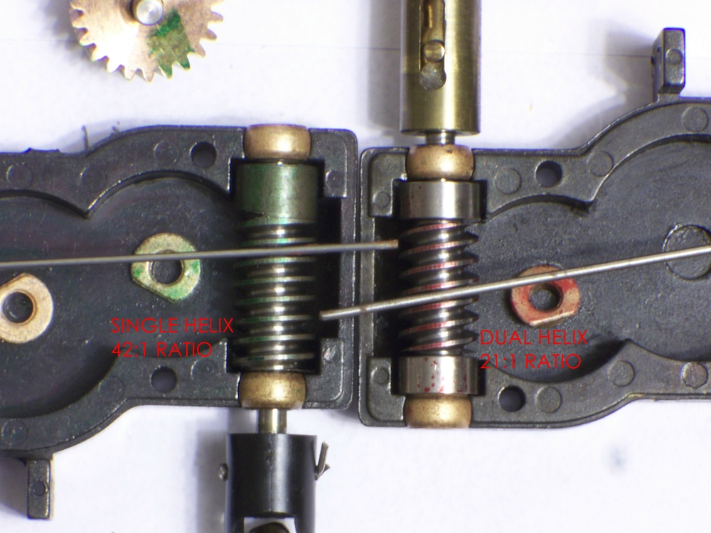
Joe what is the final drive ratio ?  16:1,  20:1  40:1 ???    What is the number of motor revolutions to turn the drive wheels one turn ?    Some of Williams locos were made by Ajin and use a different gearbox than the Samhongsa locos. I suspect this loco may have the infamous 44:1 box.  Ultimately the front and rear drivers must have the same final drive ratio.  If it is above 40:1 no 500 series Mabuchi is going to run quiet enough to please you at anything above 30smph.  Closed case motors like the Pittman motors run very quiet but don't have enough revs to acheve much more than 30smph.  I have been wondering how a 9V or even a 6V Pittman would preform with those high ratio gear-boxes.  Using the voltage to rate a motor is a poor practice but is the most common system. A better way to rate motors is the static resistance. For a given motor frame the lower the static resistance the higher the RPM will be at any given voltage.  Higher RPMs call for lower static resistance and with that comes higher current pull. All the 500 series Mabuchi motors that were used in these Williams locos that I have measured had a static resistance between .90 and 1.1 ohms. Those motors even running with no load at all pull close to three amps. Stall them and that jumps to 12A !! Which will fry most motor driver boards. Clearly these things are not designed for TMCC or DCS digital control.  Only Train America Studios made a 15A driver board capable of surviving a stall with one of those beasts.  I have used Lionel driver boards in one of those 42:1 Williams locos with a 550 motor and they have great pulling power thus are unlikely to stall and fry the board however they make far too much noise at a scale 50mph and pull enough current to ruin pickup rollers and the center rail of your layout.  I put a Mabuchi 385 in my Williams PRR L1s Mikado and ran it over at my brothers house two weeks ago. We had it pulling 27 cars at around 50smph with little problem. It runs a bit warmer than a Pittman but the Pittman won't run more than about 35smph.  Joe the 21:1 and the 42:1 gearbox used in the Williams Samhongsa as well as the Weaver brass are easily swapped however the gearbox in your loco would be very hard to swap or change ratios without original Samhongsa parts.  I have emailed you a link to the Mabuchi 385 motor that I used in the PRR L1 Mikado 12000rpm no load 2 ohm static resistance and 6A stall @12v. I also sent a second link to a 385  10000rpm no load @12v a little cooler running at 3 ohms static resistance and 4A stall @12v.  If I were doing it again I might opt for this slightly slower/cooler motor. To touch on the Pittman motors again a 9v Pittman may have enough rpm ??? but would have a shorter duty cycle you may have to stop and cool down every now and then.   Closed case motors just run warmer for a given static resistance but are a must if noise is a factor or they are used in an explosive or corrosive environment.   The Pittman motors are a bit pricy to do much experimenting but the 385 Mabuchies are cheap enough to play around a bit.  Getting a flywheel mounted and RUNNING TRUE is likely to be your biggest problem.              j

I still think you guys are looking at this differently than I am. I'm sure you understand me. I just think you've decided to run it as is.

I truly believe the gearbox needs to be addressed. Yes I know that's not possible, right?

Why ask a motor to scream that high?

So... what if.....??? I put two pulleys on custom shafts and have the motor turn the lower worm at 1:1 ratios? I think 4:1 would be better but I'll have to see what kind of pulleys I can get to work with a given belt. Anything lower would be better than this 8.5:1 that's inside here.

Maybe a stock Third Rail belt set-up would work here? I've seen the inside of my Sunset Allegheny and I think the belt system would work if I can set it up correctly. Then, I'd leave the worm to axle gear alone, and pull out the tower's idlers as they won't be used.

Last edited by Engineer-Joe

A blast from the past?  On page 1 I explained that I did one for Carl Phillips (rip).

I have never used tower gearboxes.  The extra idler gear is another source of noise, and the gearbox shows.  I am not going to look up the part number, so this part number is only for the 1/4" axle, and the Williams needs a metric size.

I used two metric axle equivalents of the NWSL Mod O.6 part 653-6, one with a wor m shaft long enough to extend from the rear cylinder front face all the way to within 1/4" of the motor shaft.  I used a pittman 8534 motor (ball bearings, silver graphite brushes), and Toyota #0 hose between motor and rear shaft.

K&S tubing is used to make shaft size compatible with the hose.  Easy to solder.

Between engines I use Speedometer cable with a square slip-joint.

The newer NWSL gear cases need to be adjusted to ensure proper mesh.

Here are a couple photos.  Sorry about the quality on the second one - Log Mallet, with 54" drivers, and NWSL gears.  Note the speedometer cable.

The first one is the MM-2 of OSN fame.  The big motor is a 9236 Pittman, and is just resting there.  The gears are 24:1 and 25:1, which makes the engines go in and out of synch.  Runs like a dream, noiselessly!gears 006Mechanisms 016

Attachments

Images (2)
  • gears 006
  • Mechanisms 016

Joe I sent both emails to the address in your profile.  Just checked my sent folder to make sure I got your address correct and looks as though I did.  If you have another email address send it to me and I will resend both links to motors.  I am aware that there are better solutions but changing gearboxes is a major undertaking that I have done twice and both times I ended up having to requarter all the drivers. No two quartering jigs are exactly the same and one quarter degree out will run but have a very slight bind at slow speeds. Changing gearboxes is an expensive option however If a $10 motor can get the job done why not give it a try. I would still like to know what the final drive ratio is. If it is indeed 40:1 or more a 385 has the torque to get the job done but anything less than 40:1 and you need more motor.  Perhaps a 395 but I have been unable to find a 395 on ebay with a 12000rpm no load speed at 12v.  However someone is selling a gearbox with a 12000rpm 395 on that auction site I will try and find it. If I remember it is only about $15.       j

@bob2 posted:

The gears are 24:1 and 25:1, which makes the engines go in and out of synch.  Runs like a dream, noiselessly!

That's a cool idea to make the running a bit more interesting.  Given it's 2-rail with no traction tires, I'm sure the slight speed mismatch doesn't make any difference, and it's neat that it'll have a more realistic visual effect.

John - it works really well - slippage is one revolution every 25.  I bet it would work with traction tires.  Slippage is on the order of a quarter inch per revolution.  I have limited space, but the locomotive pulls 14 heavy cars without breathing hard.

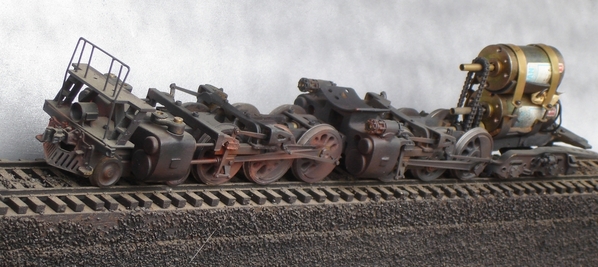
The other solution to articulated and Mallet-type synchronization is two motors.  I regard that as difficult, mechanically, since you have to cut so much out of the boiler and rear cylinder block to make it work.  I invented a "twin-spool" solution that might work great with tooth belts.  The chains were noisy.  The motor stack will only fit in a giant firebox, like the Northern Pacific Challenger:

Mechanisms 023Lobaugh NP Chall 2

Attachments

Images (2)
  • Mechanisms 023
  • Lobaugh NP Chall 2

Ohhh! Twice the available power though!

I bet belt drives would make that quiet?

@bob2 posted:

John - it works really well - slippage is one revolution every 25.  I bet it would work with traction tires.  Slippage is on the order of a quarter inch per revolution.  I have limited space, but the locomotive pulls 14 heavy cars without breathing hard.

The other solution to articulated and Mallet-type synchronization is two motors.  I regard that as difficult, mechanically, since you have to cut so much out of the boiler and rear cylinder block to make it work.  I invented a "twin-spool" solution that might work great with tooth belts.  The chains were noisy.  The motor stack will only fit in a giant firebox, like the Northern Pacific Challenger:

Mechanisms 023Lobaugh NP Chall 2

Last edited by Engineer-Joe

Wow guys, that's advanced stuff! Two motors is surely the coolest thing in an articulate.

Bob, do you have a close up of that drive shafts? Looks magic! How do you get the front engine supplied?!


Looks like we're in the same kind of trouble :-) I still work on the gear ratio for my Challenger.

There are so many things to consider! Speed, Power, Space, Noise


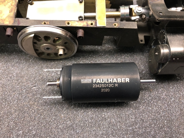
So far I tried a Faulhaber 2342 but found it a bit small.


IMG_5464


Also the ratio is too low. The wheels turn too fast at that low voltage. I try to be in the 1:25 / 1:30 range, that would mean nice slow speed and still some 50 scale miles at 5000 rpm.


That's my space concept for the bigger Faulhaber 2642. First I thought that a gear head would be a cool thing but I think it could be quite noisy so I now try to figure a way to get the power reduced with a timing belt / pulley arrangement.


IMG_0100


Kohs Challenger - technically perfectly done! Note the not huge motors by Pittman


Kohs Drive 4

Attachments

Images (3)
  • Kohs Drive 4
  • IMG_0100
  • IMG_5464
Videos (1)
Video

I could use the Kohs dropdown technique.  The chains are really noisy.

I could never put up with the boiler cutouts to accommodate that arrangement.

My front driveshaft goes straight through the rear driveshaft, right through the rear gearbox.  The idea came from the triple spool Rolls Royce engines I was flying at the time.

The NWSL gearboxes, 24 or 25:1, coupled to an 8000 series Pittman with a rubber tube, is about as quiet as you are going to get.  Ball bearings on the worm shaft are imperative, and you cannot have loose axle bearings, either on the gearbox or the frame bearings (driving boxes).

@bob2 posted:

I could use the Kohs dropdown technique.  The chains are really noisy.

I could never put up with the boiler cutouts to accommodate that arrangement.

My front driveshaft goes straight through the rear driveshaft, right through the rear gearbox.  The idea came from the triple spool Rolls Royce engines I was flying at the time.

The NWSL gearboxes, 24 or 25:1, coupled to an 8000 series Pittman with a rubber tube, is about as quiet as you are going to get.  Ball bearings on the worm shaft are imperative, and you cannot have loose axle bearings, either on the gearbox or the frame bearings (driving boxes).

Very impressive! so you use a hollow shaft - omg. I would love to learn more about your invention - isn't there a lot of friction involved? Do the two shafts have contact over all the length or just on entrance / exit points? You're a great modeller!

Log MalletYes - lots of friction.  And the outer tube is brass, so structurally not great.  But that part is not a problem.  The friction is not a problem in reality, because when running they barely move with respect to each other.

The big problem was the special ball bearings for the rear worm shaft.  They were list price around $60 each.  I got "comped" for two - they offered, and I accepted.

again, those chains are the only serious problem - the design is otherwise good.  You would need smaller diameter motors for the UP Challenger.

The better solution is the Mod 0.6 in the rear and Mod 0.5 in front.  Guaranteed in and out of synch.  Works on even the smallest Mallet.  See photo above - those are 54" drivers, and note that you cannot see the drive shaft.  All drivers are powered.  (All drivers ride in ball bearings as well, but I will not be doing that again soon.  Made no difference.)  Oh - 17/64, Auel tender trucks.  Front cylinder block is aluminum for weight balance.

Attachments

Images (1)
  • Log Mallet
Last edited by bob2

I am excited to try a belt system. I think it will solve several issues at once. I maybe wrong. Scott at 3rd Rail has helped me here again. Thank you.

I need to get a new 3mm? shaft about 6cm long? Possibly a new flywheel too? I'm thinking cutting one from the plastic dowel I bought for an Aristocraft Dash9 conversion I did years back. I may even hollow it out?? Lots of ideas and much testing.

Now it will just take some accurate workmanship by me and to see if my idea is on track!

Last edited by Engineer-Joe

I'll be at this soon. Parts are starting to show up. Either it will work or it won't.

I'll be setting what's acceptable as a solution to my standards. Quiet, smooth, and strong comes to mind here.

DSC_1242

Our grandson will also let me know if my work is acceptable. I can always put in a better motor if this goes in the right direction. If not, she's a shelf queen for our grandson.

Attachments

Images (1)
  • DSC_1242

Well? I'm pretty happy with some of the work. It runs very quiet now! Not like she's falling apart trying to achieve 40 MPH or more.

Gearing maybe too low but workable. I think this needs that Pitmann with bearings Pat sent me. I want to use that in another project so I'm waffling. The stock motor (rs545?)  is rough.

Here's just a quick video runby. I pushed the handle up to 8 or 9 volts and she took off. It doesn't mean she can't go slow. It's running on a bridge rectifier and nothing more!

A good motor control board would be interesting now.

She now has a thin plastic flywheel just for a tach tape that not used yet. Belt drive. I have to decide to put more money into her or not. MTH PS3 board set? old PS2 set and upgrade a different engine? Better motor now?

It was fun to play with.... engineering wise.

and a slower runby

track noise is way louder since I ballasted it.

Last edited by Engineer-Joe

I ran the engine around last night for our grandson. We agreed that it runs much quieter now. On the third lap it screeched to a halt? I tore it apart today and all that's wrong is a broken wire! I figured it would be my work on the drive.

Here's a pic inside of my hot rod lincoln.....

DSC_1252

I figured I should take a video while it's apart to show what it runs like now.

Attachments

Images (1)
  • DSC_1252
Last edited by Engineer-Joe

Add Reply

Post

OGR Publishing, Inc., 1310 Eastside Centre Ct, Suite 6, Mountain Home, AR 72653
800-980-OGRR (6477)
www.ogaugerr.com

×
×
×
×
Link copied to your clipboard.
×
×