Hi guys,
I have been looking through the #6008 Atlas O 3-Rail layouts book, for a track plan. However, when I try to recreate a track plan in Anyrail or SCARM, it looks nothing like the drawing. What am I doing wrong?


|
|
Hi guys,
I have been looking through the #6008 Atlas O 3-Rail layouts book, for a track plan. However, when I try to recreate a track plan in Anyrail or SCARM, it looks nothing like the drawing. What am I doing wrong?
Replies sorted oldest to newest
You really must remember that most of us are not clairvoyant. How about attaching a picture of the Atlas plan AND a copy of your SCARM file? Then, maybe somebody can help you.
Chuck
@PRR1950 posted:You really must remember that most of us are not clairvoyant. How about attaching a picture of the Atlas plan AND a copy of your SCARM file? Then, maybe somebody can help you.
Chuck
I am having issues posting a SCARM file, so I am going to post one and see if it will work. (This is for a separate, standard gauge section, which will run underneath a modified 'Cave Creek Central' track plan by Atlas. It is O-16 on pages 43-44.) I tried to create the Cave Creek Central plan but gave up when it was looking nothing like the image in the book.
Your post of the SCARM file above worked fine; I was able to download it and open it. So, now, how about your actual SCARM file with issues and a photo of that ATLAS plan? Many of us might not have access to that book.
Chuck
PS: I'm signing off for the night, but will look again tomorrow some time.
This is the layout you mentioned. I;m not clear what layout plan you are trying to recreate.
Jan
https://shop.atlasrr.com/p-443...e-creek-central.aspx

I figured I might go with a track plan like these. It was created in Anyrail, as I couldn't get it to work in SCARM. This is more or less what I am aiming for.
I took a look at the AnyRail file settings. One reason the 2 might not match is because AnyRail is more forgiving with it's default track joining tolerances. It joins tracks that are up to .125" (1/8") and 3° apart whereas SCARM uses only .079" (just over 1/12") and 2°. Therefore, if the tracks are "close" to the AnyRail tolerances, they'll join in AnyRail, but not in SCARM and the resulting design in SCARM will end up looking quite different depending on where the disconnects are during the design process. FWIW, RR-Track uses a default tolerance of .05" and doesn't show the angle. It may show that somewhere in the documentation, but I don't see any option to change whatever they use. That said, I'm not saying that changing the tolerance settings in SCARM will solve your problem and get you matching designs. You didn't post your SCARM file, so I have no way of knowing what else might be involved.
Alex,
Just one comment about your multi-level plan; think about what with, or how, you plan to support the upper level, and then think about how that affects what you can see of your trains on the lower level. If you are going to build a table layout, my suggestion would be to keep the lower level on the outside (all the way around) with the upper level fitting in the middle. Conversely (I think??), if your building an around the walls layout, keep your lower level closest to the front and your upper level to the back (nearest the wall) unless you intend to hide what's behind the upper level. Hmmm, maybe not so conversely after all.
Chuck
@DoubleDAZ posted:I took a look at the AnyRail file settings. One reason the 2 might not match is because AnyRail is more forgiving with it's default track joining tolerances. It joins tracks that are up to .125" (1/8") and 3° apart whereas SCARM uses only .079" (just over 1/12") and 2°. Therefore, if the tracks are "close" to the AnyRail tolerances, they'll join in AnyRail, but not in SCARM and the resulting design in SCARM will end up looking quite different depending on where the disconnects are during the design process. FWIW, RR-Track uses a default tolerance of .05" and doesn't show the angle. It may show that somewhere in the documentation, but I don't see any option to change whatever they use. That said, I'm not saying that changing the tolerance settings in SCARM will solve your problem and get you matching designs. You didn't post your SCARM file, so I have no way of knowing what else might be involved.
Adding to what Dave said, from the SCARM blog: http://www.scarm.info/blog/pro...a-given-layout-plan/
Thanks guys for the help. I was able to get things working. I looked at Cave Creek Central and modified it to create my own track plan. I like how it looks, but I'd like some feedback. For example, is there anything that I should change?
I do have some 18 and 21 inch coaches, so is overhang going to be an issue?
Yes, reverse the 2 crossovers at the top left from right hand to left hand crossovers. As now designed, you have a run-around track that you can only exit by reversing.
Do you have enough room to walk all the way around this plan? If not, you will have to build pop-ups in the middle of each loop to access track unreachable from the "front."
Since it appears that O81 is your outside loop and O72 is your inside loop, you should have no clearance problems with your passenger cars.
Chuck
The clearance around your loops varies from 4.0” at the O-54 switches to 4.5” at the #5 switches. Even though the O-72/O-81 curves are wide, I think it’s hard to say whether or not your particular equipment will hit without setting up a test.
Dave,
Good catch on the O54 switches, but I think the bigger issue is that the 21" coaches might not traverse those switches very well at speed, or at all. My recommendation would be to change to O72 switches at the minimum (except for spurs the passenger cars will never used), but my preference would be to use all #5 switches which should insure that all mainline separations stay at 4.5" minimum.
Chuck
I don't have any experience with 21" cars and O54 switches, but I did a version with some #5 switches in the upper left. However, they don't fit in the center or in the upper right due to their length. I was able to replace all but 1 flex track, but flex might be preferred over cutting small fitter pieces. I don't know why the top was so close to the edge, so I moved it down some.


Hi all,
Thanks for the advice. I had the layout against the back wall as the room is 22' 8" x 15' 2". So, if you were wondering about the location of where the layout will be, it will not be an island, but more of an 'around the room' type. Dave, I looked at your changes and I made some adjustments to my track plan. I took notes from you and PRR1950 about clearance issues, so I'm hoping these changes will work.
Update - I managed to remove most of the O54 switches, will figure out how to get rid of the last few.
Works for me, Alex. Good luck with the build.
@DoubleDAZ posted:Works for me, Alex. Good luck with the build.
Thanks Dave!
Made another variant recently, with a turntable. Tried to remove all the O54 curves and replaced them with wider ones where possible.
Like your new variant, just a question and comment. First, do you still plan to run an upper level Standard Gauge layout? Second, would you consider changing the top portion of the Cave Creek based on the suggestion I've attached? Third, and an even more complicated suggestion would be to consider placing your yard within the same loop where you've now placed a turntable. The third suggestion also has the benefit of narrowing your table at the top and making any necessary "reach" a bit easier.
Chuck
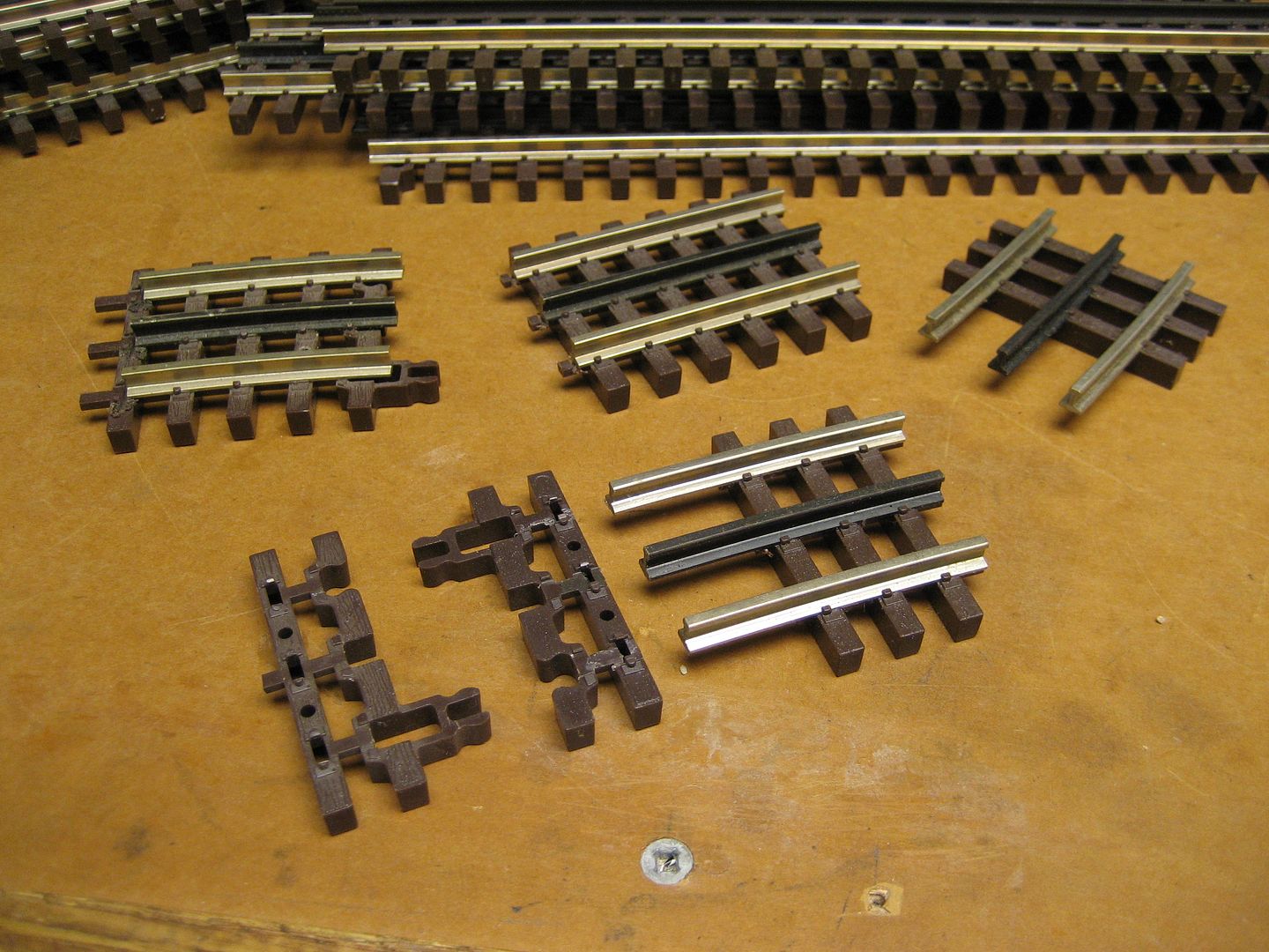
Custom layout may require a few custom track pieces. Atlas has track end pieces for custom cuts.
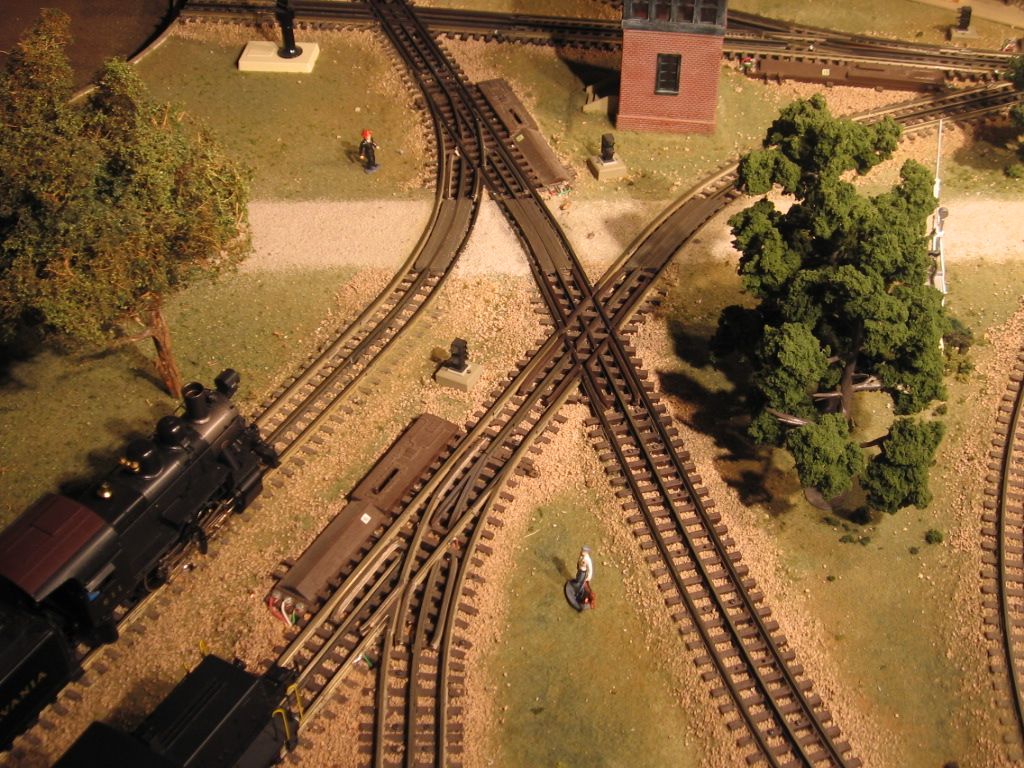
Slight change in direction, gravel road way.

Access to this requires an OGR Forum Supporting Membership
