All,
Thanks for the input! Some more information based on questions and comments above.
Stan,
Yes your diagram is correct. Each section the relay controls is about 10 tracks long. Then 1 track of always on, then one track of isolated outside rail for detection, then 1 more track of always on.
I am actually using Arduino Mega so 16 inputs and 16 outputs are not trouble. The relay board has 16 inputs.
"So each detector output simply drives the relay coil of the trailing block." That is the classic way. In fact I had used that before with Gargraves track. Because in the GG track all rails are isolated with the wooden ties, its easy! Block N's outer rail activates a relay that kills N-1's center rail. When Block N is clear the relay de-energizes and block N-1 center rail gets hot again.
By the way, The one thing I learned from the first time doing the classic way is to leave a short always on segment between blocks. Prevents stalls on the block transitions.
But ... In this particular application I used all old O-27 tracks!!!
There are two helixes each made of O-27 ovals 4 curves, 1 straight, 4 curves, 1 straight. The helixes rise for 5 and 1/2 turns, elevating 5 inches per turn. This gives a grade of just under 5%.
I manually converted a bunch of straights to be isolated outer rail. But the thought of converting over 100 pieces of 027 track was enough to make me mail order the arduino and relay board.
John,
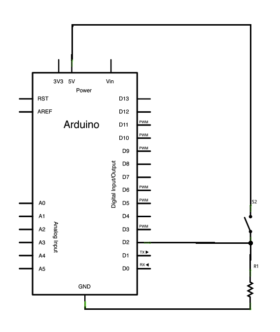
Check out the clever way the arduino folks handle debounce without interrupts. They simply record the time in millis() when the HIGH is detected in the loop() . Then they check again to see if it has stayed HIGH for whatever bounce time. I simply refactored there scalars to arrays for the 16 inputs and check each one in a for() loop in the main loop() function.
JGL and Chaos,
Thats three votes for optical isolators... Interesting.
Yes the original plan ties the +5v of the Arduino power to the Common AC ground of the train transformer. Sharing a ground does not allow AC to flow to the arduino. There is no potential / return to cause current flow. I have used that same trick before. DC powered relay sharing common ground with AC outer rail and activating the relay on isolated rail....