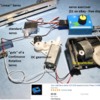
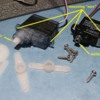
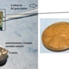
I know that the arduino Uno can be programmed to do a series of things consecutively. However, I need to be able to start the program with a servo motor running to one end of its travel, holding there, another servo running and holding, a electromagnet firing, then a third servo running. If I can get some direction on how to do it, I'd like to try it myself. After studying what I find on the net I'm totally lost.

Thanks for any suggestions.

Jay

Original Post

Replies sorted oldest to newest

The ticked is as mentioned, you have to start an operation and then go on to the next one, etc.  Then you just loop around and keep tabs on how your processes are proceeding, and do any necessary processing as they proceed and complete.

Most little real-time applications will simply have a processing loop that is continually running, and you just bop out to start and terminate processes as you go.  You'll also likely want to set up a timer block so you can have timers of various resolutions for process control.  Stuff like serial data input is typically handled using an interrupt routine unless your process loop is very small and fast.

GRJ: The Arduino has a setup routine that happens before anything else in your program and a loop that runs repeatedly just as you have described for a real-time system. Interrupts are being used in the belly of the beast but are rarely used at the surface.

Unfortunately, it doesn't appear that the Servo library has a mechanism to sync-up when the servo movement has completed. Your program can issue a command to move to a particular point (say 90 degrees) but there is nothing to say when that movement has actually been accomplished.

As shown in the video, you can issue back to back Servo.write commands in opposite directions and before the first movement is complete, the second command overrides the first.

The only way to ensure that a movement has completed is to estimate a time interval for that to happen. The published interface does not allow for interrupts or other synchronization methods.

...
myServo.write(90);
delay(100);
...

Last edited by Consolidated Leo

RTR12: I'm not sure how these things work either. They have 3 leads; power, ground, and signal. I think it uses PWM through the signal wire. But they don't have to be hooked up to the PWM pins of the Arduino (just the regular Digital I/O pins). There is a circuit board inside the servo and a potentiometer to feed position information to the unit. I'm still learning about these, too.

You can read about how the Arduino uses them in the Servo library.

Consolidated Leo posted:

GRJ: The Arduino has a setup routine that happens before anything else in your program and a loop that runs repeatedly just as you have described for a real-time system. Interrupts are being used in the belly of the beast but are rarely used at the surface.
...

Sure, any uP application needs an initialization procedure that initializes the hardware, etc.

I'm used to writing all the code, including the interrupt routines for various functions.  I'm getting spoiled by the new PIC MPLAB X with all the canned functions for generating code for timers, serial data, etc.

I did some work with the Arduino, and it's very easy to crank out an application with it.  I generally am using the PIC as I'm building stuff that's much smaller than any Arduino processor board, and it includes all the other interface parts as well.

That makes sense, GRJ. Again, all of that is buried in the library code so we don't have to deal with that. But it helps explain how these things work. If I would have had access to servos when I was about 10 years old, I'd have been all over this. 

I understand wanting to go with the smaller footprint for engines and rolling stock. You've got to adjust with working in close quarters.

The Arduino started out as a way to get young people interested in the engineering and science fields of endeavor. They will need to have an understanding of the machines that we develop.

In model railroading, the Arduino is in that sweet spot between technical and simple with a lot of motivation to drive things along. I'm sure that there are a lot of modelers here that would be using them for all sorts of things if they only knew how. After all, these are electric trains.

Consolidated Leo posted:

RTR12: I'm not sure how these things work either. They have 3 leads; power, ground, and signal. I think it uses PWM through the signal wire. But they don't have to be hooked up to the PWM pins of the Arduino (just the regular Digital I/O pins). There is a circuit board inside the servo and a potentiometer to feed position information to the unit. I'm still learning about these, too.

You can read about how the Arduino uses them in the Servo library.

Thanks, I will check out the library. I think after that I might order a couple to play with and experiment with the software for feedback as GRJ indicates below.

gunrunnerjohn posted:

The PWM servos use feedback internally for positioning, typically a pot, but you don't have visibility to the position.  It's assumed that you know the pulse width you're feeding it, so you should know the position.

I gotta look at the library above, but from your post there must be a way to keep track of position in software then. Maybe the library will explain further about software workings. Feedback seems nice, but maybe not needed like I thought it would be? Gotta read up on servos too!

It is my understanding that there are all kinds of servos available with lots of different features including feedback from the internal potentiometer. This would be one way to determine what the actual position of the servo is. Then the program could react acordingly.

The price range goes from about $3 for a hobby servo from Asia, to astronomical. The cost for the feedback seems excessive for anything that I would want to try for a switch machine on a model railroad.

In GRJ's sample code, they are using an external potentiometer connected to one of the analog input pins to determine the position for the servo. As I said before, there is no synchronization method for the program to use to determine when the servo has completed its movement. A suitable time interval is the only way to be sure when it's done.

It's funny that the hobby servos are all advertised as being really fast. I guess in the RC (radio control) world of racing cars, airplanes, and quad-copters, that's an important issue. Speeds are touted as being about 0.12 seconds to move 60 degrees.

In the railroad world, switch machines are meant to run slowly to achieve a more realistic look and operation. But I think that by giving the servo small increments in succession, a slower movement can be accomplished. That's a good thing.

If you buy a servo that has feedback, I suspect you'll be paying more than you might imagine.  I worked with a lot of servo driven aircraft instruments in the 1970's and 1980's, and providing external angle feedback was a big deal.

As you correctly observe, you can simply change the PWM code slowly to achieve the result you desire, that doesn't preclude using the inexpensive model servos.

From what I gather, small hobby servos are all made in China or Taiwan. There are name brands like HiTec, Futaba, Tower Pro, and countless others. Some are Chinese brand names. Others are US brand names. There are clones that look very much like the real thing and come with a corresponding lower price; probably went in the reject bin for the name brand models.

It's difficult to know which ones are reliable enough to spend money on when your project is counting on a narrow price range. If I want to beat the price for a switch machine, it has to be around $10 or less.

The failure rate seems to be higher than usual on units of this size. People who fly model aircraft hate it when they fail in their $3000 model planes and come to a crashing realization that they should have bought the more expensive servo. It's good that model railroads don't leave the ground; at least not on purpose.

I'm tending toward the Tower Pro MG996R for about $8. Some ebay claims don't add up to the real thing. The pictures show things like "TowardPro" on the label. I may have to lower my expectations and just order some.

I have no experience in this area so recommendations are welcome? Please include make and model. Thanks!

Last edited by Consolidated Leo

I'm alive and well despite the sub zero weather. Been hibernating inside trying to come up with some code that actually works for parts of my project. Close on some things but no cigar. Been a long time (50+ years) since I did any computer programming. Then it was 80 column punch cards and hope the computer opp didn't drop your deck of cards.

One thing that I found out about the Arduino 328P models, including the UNO, is that there's not a lot of dynamic memory space. What that means is that too many diagnostic Serial.println statements can corrupt the stack. So I advise that you use them sparingly. Don't leave them in your code once you've ironed out a particular section. They'll take up too much space. It's sometimes easier to leave them where they are but comment them out with the leading double slashes. Also, keep the messages you print short. Once the stack becomes corrupted, the processor will get lost and your program will crash. The only symptom is that everything stops.

Professor Chaos posted:

You can prevent string literals in print statements from being copied into RAM by using the F() macro.

That's correct. It puts the strings into program memory instead. I don't use the P macro directly but I do use that technique to store and retrieve immutable strings as keywords. Still a valid way to make use of program memory for unchanging data.

trainman129 posted:

Added info: servos 1 and 3 are continuous rotation. Second is normal. I suspect that nos. one and three will be stopped by a limit switch of some kind.

What exact  part # or model # are you using as a continuous rotation "servo".  There are servo mechanisms that have been modified to allow continuous rotation - but the modification renders the standard servo library functions useless.  Most if not all hobby servo mechanisms have a limited range of motion - maybe 3/4 of a rotation at most.  There are mechanical stops to prevent it from continuous rotation.  Some servos even use the limited range of a 3/4-turn sensor potentiometer as the limiting mechanism.  You can remove these mechanical stops and/or sensor potentiometer yourself, or just buy modified servos. Now you basically have just a DC gearmotor - or 2-wires directly connected to a DC motor plus gearbox.

Positive DC voltage spins it one way, negative DC voltage spins it the other way.  You will need some kind of sensor (lever switch, optical or magnetic sensor, etc.) to detect when the output shaft makes a revolution.  Then count 3 and stop the voltage.  Apply the reverse voltage and again count 3 revolutions and stop the voltage. 

Control the speed of rotation using standard pulse-width-modulation PWM functions.  Applying 5V direct to the motor of a modified servo will make 1 revolution in a fraction of a second; hence use PWM to slow it down.  Servo library functions also use PWM to communicate with servo mechanism but it's a different protocol and hence not relevant to control continuous rotation DC gearmotors. 

I'm sure there are exceptions to my blanket statements.

Last edited by stan2004

The Servo library does work with continuous rotating servos as well as the standard types. 

Standard servos allow the shaft to be positioned at various angles, usually between 0 and 180 degrees. Continuous rotation servos allow the rotation of the shaft to be set to various speeds.

The Servo.write function then takes a parameter to set the speed of rotation.

Writes a value to the servo, controlling the shaft accordingly. On a standard servo, this will set the angle of the shaft (in degrees), moving the shaft to that orientation. On a continuous rotation servo, this will set the speed of the servo (with 0 being full-speed in one direction, 180 being full speed in the other, and a value near 90 being no movement).

trainman129 posted:

Trying to run a cont. rot. servo in one direction multiple rotations then stop it. Later , run it in the opposite direction the same number of revs.  Servo wants to stop and chance direction by itself. Must have a bug in the code somewhere.

If you would like me to look over your program, you could attach it here as a file (add attachments; below). Sometimes it just takes another set of eyeballs to spot a problem.

That's a good summary of how the standard servo.write functions can control the speed and direction of a 3-wire "continuous rotation servo".   Just want to be sure you have such a widget rather than a standard servo mechanism that has been modified for continuous rotation. 

Sorry for any confusion.  I didn't realize how far things have progressed.  Just a few years ago, hobbyists were lucky to find standard servos that were mechanically modified for continuous rotation.  For minimal additional cost now there are versions that are additionally electrically modified to re-interpret the servo.write position commands as speed/direction.  Very useful! 

Last edited by stan2004
rtr12 posted:

While looking for servos I found this. Might be of interest, tons of servo info.  Servo Database

This database is interesting for a number of reasons. It shows what a wide variety of models are available for servo motors. The big stuff, the industrial size servo "systems", can run into hundreds of thousands of dollars. And they're all over the internet. My searches have led me to places where they want you to ask for a quote. Then you know that it's time to move on.

I finally got one part of my program working. Relief is at hand. At least until I start to work on the second part.

Been a strange day in upstate NY. Started out at 60 deg this morning. Now we are in a major winter snowstorm. Who says the weather isn't changing???

Seems like I started something with my question. The world of servos is wide open for all kinds of animations on a layout. Be interesting to watch and see where this thread goes.

Last edited by trainman129

From what I can tell, most (all?) "Continuous Rotation Servo" are modified standard servos.  The operative term being "modified" - done so by the hobbyist (plenty of online instructions) or by paying the distributor a few extra bucks to do so.  If the objective is to use the existing Arduino servo library commands then why not modify a standard servo or even a CRS to use a, say, 5-turn or 10-turn sensor potentiometer instead of the standard 1-turn?  This potentiometer would mount outside the servo box - the use of external components (limit switches) was already put on the table.

So with a, say, 5-turn potentiometer, the standard servo write commands would move the servo between 0-900 degrees (rather than 0-180 degrees) more than covering 3 revolutions.  In this way, you don't need to develop software to count 3 revolutions with an external rotation sensor/limit-switch.  It's not clear if your application is sensitive to cumulative angle error.  Since using a CRS using the standard library functions is not calibrated in speed, it seems you will drift over time from the original starting position if 3 revolutions is done by running the gearmotor for a fixed period of time without feedback.  Of course your application may not care about this in which case never mind!

Separately, if the discussion is about Arduino control for layout animations what's neat about the CRS approach is you can take the circuit board out and drive your own DC gearmotor CW and CCW using Arduino library commands.  So you still have the 1-wire control signal from the Arduino module to the servo board, and 2 wires from the servo board to your DC gearmotor.  Very simple hookup.  eBay and others have inexpensive DC gearmotors that may be easier to mount or with a more suitable speed range than what you get in a standard servo.

dc gearmotor low cost

Attachments

Images (1)
  • dc gearmotor low cost
Last edited by stan2004

Would be interesting to know the application and whether a 'servo' is the right drive for whatever is being done. A lot of good cheap stepper motors that have tons of torque out there. Cheap cog belts too. (Parts used in 3D printers - good and plenty.). When you send so many steps to the motor in either direction, it pretty much goes there unless there is a major major bind in your mechanism. Repeatable, doesn't need position or rotational feedback (although you can use 'limit switches' to drive into a fixed stopping point, also facilitated with the Arduino programs and I/O

Can we say stepper motor? There are many direct drive and geared steppers, those you can actually determine zero, step at any rate you desire, and have it rotate as many times as you like under program control.  Tons of stepper motor drivers for Arduino as well as libraries to control stepper motors.

For cockpit panel instruments, before everything went digital, we used stepper motors to replace DC servos.  We actually had real angle feedback on them, but it was still more cost effective and reliable than the DC servos with the pot.

gunrunnerjohn posted:

Can we say stepper motor?

Now you've done it, John! I believe that the CRS (constant rotation servos) grew out of the R/C hobbyists who just wanted drive wheels for their robots. I'm not sure why? You would think that driving a robot around would require more positional feedback than ever. Maybe costs were lower or they just didn't want to mess with the stepper motor driver boards. But whatever the motivation, people have been "modifying" standard servos into CRS for a while.

I'm not experienced on stepper motors either but I do think it takes some additional hardware to drive them properly. Motor control and H-bridge controls are not generally done in software as far as I know.

Having watched a couple of videos on the Arduino running stepper motors, I take back what I said last time about not using software to control them. Although they do use additional hardware to drive the motor, the programs tell them when to take each step and how long to wait before taking another one. The delay determines the speed. These methods simply involve regular digital I/O pins to generate the pulses for the stepper motor.

A cursory look at my favorite auction site yields prices and varieties on a par with servo motors. Apparently they are often used with the mechanisms for 3D printers. Mounting brackets are generally more expensive than the stepper motors that they are meant to hold.

And so, stepper motors would seem to be a valid alternative to continuous rotation servos and may be more scalable (they can do some heavy lifting with the proper driving hardware). However, the driving hardware, though simple and available, adds to the overall cost.

gunrunnerjohn posted:

I just figured it's another option that's worth considering.

GRJ: Options are always a good thing. I admire it when people come up with different approaches to problem solving. Your experience in the aerospace field and flight instrumentation is not wasted on us. Folks on the Electrical Forum are always watching for your input to back up their pursuits. I personally give you high marks for much of your advice and direction. Keep it up.

Last edited by Consolidated Leo
rtr12 posted:

Oh my, you guys are already on stepper motors and I still have a few hundred thousand servos left to look at!

RTR12: Don't worry! You're abbreviation guide has given you a special exemption because of the number of forumites (including me) that it has helped. So if you have fallen behind on stepper motors, that's OK (okie-dokie). They're just motors that are used for more precise movements due to their design. You'll be fine.

This might be off topic, but related. I have been designing a model railroad layout and using a PLC to control it. I am mainly doing this as a learning tool to teach myself PLC programming. I have not posted about this mainly because its impractical and probably would not be of interest to most. I have never used the Adriano, but I would think programming it may have some similarities to ladder logic and I might be able to help.

Mike


Attachments

Images (3)
  • Button box and alarm light tower
  • PLC controls with isolated inputs
  • manual-automatic control of layout
mikeexplorer posted:

I would think programming it may have some similarities to ladder logic and I might be able to help.

Mike: Ladder logic is an old school method of industrial programming with relays; 2 in series for AND, 2 in parallel for OR. I realize that they still use ladder logic for modern PLC (programmable logic controllers) systems but that's because they didn't want to have to change things over when they had so much invested in the older technology. That and the fact that the transition most likely involved both older equipment along with the new. It's odd that ladder logic is still used in industrial control environments.

The Arduino (pronounced: ard - as in aardvark, ui - as in ween from Haloween, and no - as in no meaning negative) is much less restrictive. Of course it does involve logic but the mechanisms of the programming language are much more open.

The Arduino uses a version of the "C++" programming language that came from the older "C" language developed at Bell Labs. C++ is an object oriented language that allows for the creation of new entities that have common functionality. For example: you can create an LED object that can have methods to change its state like so:

#define LED_PIN 13

LED myLed(LED_PIN);
myLed.on();
delay(1000);
myLed.off();

These objects in the Arduino world are refered to as a "library". There are a number of libraries already available for the Arduino including a Servo library (as described here).

There's a lot more to it but I think you've got the idea. There are plenty of books, videos, etc about the Arduino platform as well as the C++ programming language. You might want to give them a try.

  -- Leo

Last edited by Consolidated Leo

It seems to me the take-away of this discussion is the use of the servo.write functions to easily get up and running with an Arduino and a servo.   The servo has 3-wires going to it.  2 are just the +5V power and ground that the Arduino has anyway.  The 3rd is a single digital output pin.  The single servo.write(0) command sends the servo to one end, the single servo.write (180) sends it to the other end.  And arguments in-between send the servo to some angle in-between.  Easy.

Then build or buy a modified servo which has come to be known as a Continuous Rotation Servo and now the same commands send the mechanism spinning in one direction or the other direction and coming to a halt by sending the single servo.write(90) or mid-value command.  Easy.

If you are going to mess with servos, I highly recommend the $1 servo-tester you can get on eBay.  Simply apply 5V DC.  Attach 1 (or up to 3) servo mechanisms via the standard 3-wire connector.  Then by turning the knob on the exerciser, you effectively generate servo.write(x) commands so you can verify operation of your servo mechanism before writing a single line of Arduino code.   This development tool is obviously handy when mating your servo to your animation.

Again, I think the idea here is to get up and running quickly with minimal fuss.  That's what is interesting about the CRS since it accepts and interprets Arduino servo.write commands.  As I've already confessed, I was not aware of this development until Leo pointed it out.  Anyway, to further the discussion about using servos for layout animations, here are a couple more ideas that might help Arduino enthusiasts willing to modify (or pay a couple bucks extra to modify) a standard servo as is done with a Continuous Rotation Servo.

Watch the 4 mechanisms in action (one being an un-modified standard servo).

diy servo - position and continuous rotation

In photo (and video), I modified the "guts" of a standard servo to make a CRS.  As mentioned in a previous post, I then replaced the DC motor within the CRS with a cheap DC gearmotor.  In fact, I show two DC gearmotors being driven together by a single CRS.  The point here was a standard servo has pretty amazing current drive capability since it can spin the integral motor at whiplash like speeds.  But if you want to go slower as you might with many layout animations, there is plenty of current capability to drive a wide variety of DC motors.

Additionally, on the top, I show a "linear" servo which is an incredibly useful mechanism for layout animations.  Sometimes you just want something to go left-to-right rather than around-and-around.

DIY linear servo

Again, it's just a modified standard servo removing the electronic guts and attaching it to a linear volume control mechanism from a remote-control audio amplifier - you've seen them...when you adjust volume from the remote, the manual volume control knob slides (or rotates) by itself.  Or you can just go up to the amp and manually slide the volume control.  It's essentially a motor-driven potentiometer.  So the potentiometer provides the feedback to the servo electronics.   I buy these surplus for a few bucks.  Again, you have the standard 3-wire connector (+5V, ground, 1-pin Arduino output) so from the Arduino perspective, the single command servo.write(0) sends the slider to one end, servo.write(180) sends the slider to the other end, and value in between send the slide to the mid-point.  Easy.

Attachments

Images (2)
  • diy servo - position and continuous rotation
  • DIY linear servo
Last edited by stan2004
stan2004 posted:

It seems to me the take-away of this discussion is the use of the servo.write functions to easily get up and running with an Arduino and a servo.


Stan: Right, but more generally, that all kinds of automation are possible with a microprocessor. Add in cheap relay modules along with homemade train detection circuits and LEDs for trackside signals and now you can build some good stuff; a reactive layout. Not exactly a new idea but now with the costs at a level that makes it very practicable.

Think about how a conventional layout could be setup to use isolated blocks to control more than one train on the same track. You could follow each train around the layout through its own transformer. You could use large bridge rectifiers (diodes to reduce voltage) to slow down a train as it approaches a more restrictive signal; trains would maintain a safe stopping distance without any operator intervention. All made possible because of the simple but sophisticated microprocessor watching over the entire enterprise.

I imagine many Arduinos around the layout controlling turnouts, led signals, power districts, talking to each other, running switcher operations in the yard to build a consist; and that's just for conventional mode. TMCC, Legacy, DCS, DCC are all candidates for automated control as well.

Sounds like fun to me!

What's amazing is you can now buy a standard servo on eBay for 99 cents free shipping.

ebay servo for one buck

And one with metal gears for not much more.  Point being I don't think the electronics inside cares whether the gears are plastic or metal - relevance of this later.

There is no shortage of resources, references, articles, etc. about servos and how they might be used in a train layout.  Though we still have no idea what kind of train animation the OP is attempting with an Arduino, the application of the modified-servo (CRS) is less well documented.  Hence, I've put together a few more thoughts on this.

DIY CRS that uses arduino servo library

To recap, a standard servo (shown on left) consists of 3 main components.  It's a (1) DC gearmotor (DC motor + gears), (2) angle sensor (typically a potentiometer), and (3) electronic guts which "knows" how to decode Arduino servo.write commands to set the angle of the output shaft between 0 and 180 degrees.  The CRS modifies this by making some minor electrical and mechanical mods; again, many online and youtube tutorials on how to do this...or most robotics/Arduino stores sell the modified servos.  The modification is really to remove the mechanical angle feedback to the electronics so that the electronics always thinks the output shaft is at the midpoint (90 degrees).  So when you command servo.write(0), the electronics drives the motor CCW but the sensor always says it's still at 90 so the motor spins in vain forever.  Likewise, command servo.write(180) and the electronics drives the motor CW but the sensor always says it's still at 90 so again it spins in vain forever in the opposite direction.

So I'm claiming the electronics to make a DIY CRS with your own DC gearmotor is as little as 99 cents!  Likewise, the electronics doesn't "know" it's driving the integral miniature DC motor that comes in a standard servo.  In other words, I'm suggesting for 99 cents, you can "throw away" the DC motor and gear mechanism - hence if doing this, I'd experiment with a plastic-gear servo.

So why do this?  First, as mentioned previously, most standard servos spin REALLY fast.   Most servos have the so-called 60 degree spec which, oddly enough, is the time it takes to spin 60 degrees.  A typical servo might spec 0.1 seconds.  So this would be 0.6 seconds to spin one revolution (not that a standard servo can make a full rotation) or 100 RPM.   I'm sure there are train layout animations that rotate 100 RPMs but I'd say this is a bit fast; the Newsstand dog running around the hydrant may even be faster than 100 RPM!   Yes, you can slow down the speed by changing the servo.write(x) command to something other than x=0, x=90, or x=180.  What actually happens when you do this and the fine-print is a subject for a separate discussion.

The point is you can get DC gearmotors in the, say, 10 RPM range for a couple bucks that might better suit train type animations.  I showed some examples in an earlier post.

The other consideration with most standard servos is the common ear mounting method may be awkward to mate to your specific animation.  Likewise the set of mounting arms that snap on the knurled output shaft may or may not play well.  To be sure, there is a whole after-market of plastic and metal arms, extensions, you-name-it that can make the job easier. 

standard servo mounting considerations

In my experience making custom one-off model layout animations, much more time is spent designing, prototyping, fiddling, adjusting, and fussing with the moving parts or mechanism...as opposed to the electronics.  Obviously guys have been using DC gear motors since day 1 to make clever animations...simply adjusting the DC voltage to get the animation just right.  It's been more work to orchestrate animations where the motor runs in both directions in a complex timed sequence.  This is where the Arduino is going to shine. 


Attachments

Images (3)
  • ebay servo for one buck
  • DIY CRS that uses arduino servo library
  • standard servo mounting considerations
Last edited by stan2004

Stan: We have heard from the OP but he is too busy working on his programming skills to be bothered with our ramblings. Pretty good ramblings, though! It looks like we've got lots of options for servos, stepper motors, linear servo driven sliders (I've seen those with premier audio mixers for "faders"), and now you're telling us that regular DC motors that you can get with reduced gear ratios can be controlled from the electronics inside a tiny 99¢ servo. That's all good news.

So the control wire to the servo is driven by PWM either from the manual tester or from the Arduino servo library operations. And the electronics inside the servo use the PWM to drive a DC motor. Do you know if the power and ground can be used with say 12 volts to drive larger motors? Is the one in your video running at 5 volts? You'd have to use a common ground of course but that's easy. Do we know what the electronics in the servo consists of?

I have published over fifteen articles describing servo based track switch control and animation projects. I've used a number of control devices from a wide variety of sources. Some inexpensive servos can be a bit tricky, so watch out. These projects included manual and automatic sequencing triggered by magnetic detectors and both smart and regular IR detectors. Servos are amazing and can be used in an almost unlimited way to enhance action on a layout. I encourage forum members to keep experimenting and report their results which I will happily study.

Consolidated Leo posted:
mikeexplorer posted:

I would think programming it may have some similarities to ladder logic and I might be able to help.

Mike: Ladder logic is an old school method of industrial programming with relays; 2 in series for AND, 2 in parallel for OR. I realize that they still use ladder logic for modern PLC (programmable logic controllers) systems but that's because they didn't want to have to change things over when they had so much invested in the older technology. That and the fact that the transition most likely involved both older equipment along with the new. It's odd that ladder logic is still used in industrial control environments.

The Arduino (pronounced: ard - as in aardvark, ui - as in ween from Haloween, and no - as in no meaning negative) is much less restrictive. Of course it does involve logic but the mechanisms of the programming language are much more open.

The Arduino uses a version of the "C++" programming language that came from the older "C" language developed at Bell Labs. C++ is an object oriented language that allows for the creation of new entities that have common functionality. For example: you can create an LED object that can have methods to change its state like so:

#define LED_PIN 13

LED myLed(LED_PIN);
myLed.on();
delay(1000);
myLed.off();

These objects in the Arduino world are refered to as a "library". There are a number of libraries already available for the Arduino including a Servo library (as described here).

There's a lot more to it but I think you've got the idea. There are plenty of books, videos, etc about the Arduino platform as well as the C++ programming language. You might want to give them a try.

  -- Leo

Oh I agree, Ladder Logic is quite different from what you describe. I have not looked into Arduino, but from what I see, you can use modules with different functions for input & output. It reminds me of years back using an old TRS-80 Color Computer, plug in cards could expands its input-output ability and once I designed a control system for environment and wrote the software in a program similar to C+.  It supported both digital and analog input & output.

I have found so far with ladder logic, it does not allow loops. It trips a fault in the PLC due to the scan time. This is quite different then C+ or any similar programming language.

My purpose for doing this project is to learn ladder logic because in my job, we use PLC's for controls. The model railway gives me a real world example since the is variation on the layout as far as train speed, tripping block detects, and so forth. The parts I used to build this came from my previous job where they were scrapping old machines and I took these parts. Eventually I would like this to control my ceiling layout with an HMI panel.

For most other people, this type of project is impractical.

Mike


Mike: With your background, I'm sure that you will be most helpful with upcoming programming tasks. From what I know about industrial control systems, they're mighty cool looking; big buttons, lots of flashing lights, connections all over the place. Not exactly science fiction but you could do worse. I have a brother who works with PLC stuff in a steel mill. In his last job, he worked with the rail system at another steel mill. I was so jealous.

I hope your project works out for you. Keep in touch. I hang out around the Electrical Forum most of the time.

BOB WALKER posted:

These projects included manual and automatic sequencing triggered by magnetic detectors and both smart and regular IR detectors. Servos are amazing and can be used in an almost unlimited way to enhance action on a layout.

Bob: I've seen some of your stuff on YouTube; the car unloader and the station with the backup detection. Pretty cool! That's the kind of ingenuity that gets others to realize that they too might be able to put together their dream project. I'd say there's a lot of room for innovation that can be brought out in a model railroad. The kind of stuff that makes people wonder, "How'd they do that?"

Consolidated Leo posted:

... Do you know if the power and ground can be used with say 12 volts to drive larger motors?

---Is the one in your video running at 5 volts? You'd have to use a common ground of course but that's easy.

...Do we know what the electronics in the servo consists of?

1.  For years the standard operating voltage has been around 5V...or in practice 4 or 5 rechargeable batteries, 1.2V each, so, say, 4.8V to 6V DC.  From what I can tell, there's some hand-wringing going on about how to deal with Lithium/LiPo battery packs which run around 3.7V, 7.4V (for 2), etc.  I am not aware of any standard hobby servo that accepts 12V. 

2. Yes, the servo exerciser is powered by 5V DC coming in on the right side in my picture/video.  That same 5V DC (red and black wires) simply passes thru to 2 of the 3 wires going to each servo.  Same for an Arduino set-up.  The 5V DC for the Arduino itself is 2 of the 3 wires going to each servo.  Of course, that's just goes to the attraction - the 5V DC is already there to power the Arduino itself.  Connect 1 more wire and you're off to the races!

sweep_bb

3. I'm sure someone who's been in the "game" for a while can dig out an early servo circuit which used all "analog" electronics, but I can't imagine any servo today that does not use a programmed digital IC.  It is this high-level of integration that makes me think there are no provisions to "tap in" to the tiny servo board to inject 12V or whatever to drive a bigger motor.

servo guts

I have opened to modify a wide-variety of servos and there's always one "magic" chip surrounded by a dozen or so basic components.  The magic chip might look like the 2 shown in the right photo above.

So tying it back to the topic at hand.  If the objective is to leverage the standard servo.write library and drive a modified standard servo such as a CRS, I'm suggesting you don't have to constrain yourself to the DC-motor and gear reduction of the standard servo.  A standard servo DC motor might have a measurable DC resistance of, say, 10 Ohms.  At 5V DC, that's a maximum current of 0.5 Amps which is really quite a bit of power.  I specifically picked lower-voltage DC gear motors in my previous post.  You will typically find operating currents in the fine-print which might be 0.1 Amp (100 mA) range for tiny DC gear motor.  Or just measure the DC resistance of the motor and if it's around 10 Ohms (or more), then no problem to drive it with the guts of a standard hobby servo.

At the risk of inciting mob violence, there is no such thing as a 12V DC motor.  There are zillions of DC motors that are designed to operate at 12V.  Perhaps semantics, but most DC motors that say "12V" can be driven at 5V or 4V at reduced speed and perhaps far away from its sweet-spot of power efficiency (Horsepower per Watt).  But for layout train animations you might well find a 12V motor might work just fine.  For example, measure the DC resistance and if it's 10 Ohms or more, hook it up to a 5V DC supply and see what happens.  If it spins slow/fast enough and can move your animation mechanism then you can pass go and collect 200.

Attachments

Images (2)
  • servo guts
  • sweep_bb
Last edited by stan2004

Here's a 12V gear motor mechanism you might be familiar with! 

The truck has a Mabuchi RS-365 typically thought of as a 12V DC motor.  The servo exerciser is being powered by 5V DC.

rs-365 motor resistance

To be sure, the RS-365 motor is made by the gazillions and used in many consumer appliances like hair-dryers and what not.  So I don't know if the exact version used in an O-gauge diesel truck is the one above data table from the Mabuchi website.  Most datasheets will specify the stall-current (in Amps) at some nominal operating voltage.  The stall-current is essentially the worst-case (maximum) current that the motor draws.  Ohms Law then tells you the resistance of the motor winding or effectively the worst case load on the servo electronics.  This simple calculation is one way to confirm the electronic guts of a 5V DC powered CRS can "safely" drive a different DC motor.


Attachments

Images (1)
  • rs-365 motor resistance
Last edited by stan2004

Stan: Thanks again for the information! I'm trying to understand how the standard servos actually do what they do. This video goes through some stuff that I was unsure of before. It also identifies the magic chip on the circuit board but I'm sure there are others available and in use. Here's a diagram for the KC5188:


Quite a supporting cast. The datasheet I found was not in English.

The video quickly runs through some of what has to happen to turn the input signal into the proper operations for the motor. I believe he mentioned an H-bridge setup. That's a little over my head but I think it has to do with directional control for the motor.

I also spent some time poking around in the Servo library to see how they generate the PWM signals. It has to do with the on-board timers that generate interrupts continuously. And since there's no feedback to the Arduino, there's nothing to stop the PWM signal from being sent to the servo forever.

The Servo library also has a Servo.writeMicroseconds function that takes values that correspond to the length of the pulse width beween 1 and 2 milliseconds of the 20ms wavelength. You feed it 1000 for fully CCW, 2000 for fully CW, and 1500 for the midpoint. But I don't understand how the servo electronics can interpret those signals for a CRS to affect the speed of rotation; but clearly it does.

Consolidated Leo posted:

The video quickly runs through some of what has to happen to turn the input signal into the proper operations for the motor. I believe he mentioned an H-bridge setup. That's a little over my head but I think it has to do with directional control for the motor.

That's a pretty good video - including a description near the end of the CRS...though I don't think he actually uses the terminology "Continuous Rotation Servo".  I think this is a phrase that someone coined and it stuck.  There are limitless online tutorials and video on the "H-bridge" setup.  "H-bridge" is another one of those terms that someone probably made up and it just stuck.  4 transistors and a DC motor that when drawn out in schematic form looks like the letter "H".  From the video:

H bridge

But to bring this back to OGR relevance, the video and the KC5188 diagram provide some insight into the practicality of modifying a standard hobby servo to use a larger DC motor for O-gauge animations.  If the 4 transistors of the H-bridge motor driver are integrated into the magic chip, it stands to reason they will operate at the same voltage as the chip itself.  So that would be about 5V or whatever is coming from the 2 (of 3) power wires from the Arduino connection.  To work at a higher voltage or to drive more motor current you'd need to use external transistors.

Note that your KC5188 diagram shows 2 external transistors. 

kc5188

Then, in the video, the guy describes how some larger servos have the entire H-bridge external - in the example there are 2 transistors in each of those black packages.  The magic chip is on the other side of the board.  But the H-bridge is still being supplied by 5V since that's all that's available from the 3-wire Arduino connection.

I'm sure someone out there has modified a standard hobby servo to operate at 12V.  But I figure there's a tipping point where the effort to modify the electronics of a standard hobby servo would be better spent modifying the Arduino library to drive a generic DC motor with a 12V H-bridge shield (for CRS operation), and then for standard servo operation to read an analog input pin to sense the angle from a potentiometer on the output-shaft.

external motor bridge


Consolidated Leo posted:

I also spent some time poking around in the Servo library to see how they generate the PWM signals. It has to do with the on-board timers that generate interrupts continuously. And since there's no feedback to the Arduino, there's nothing to stop the PWM signal from being sent to the servo forever.

The Servo library also has a Servo.writeMicroseconds function that takes values that correspond to the length of the pulse width beween 1 and 2 milliseconds of the 20ms wavelength. You feed it 1000 for fully CCW, 2000 for fully CW, and 1500 for the midpoint. But I don't understand how the servo electronics can interpret those signals for a CRS to affect the speed of rotation; but clearly it does.

Yeah, the video is a little vague on if/how the servo electronics affects the speed of rotation if you modify a standard servo to CRS operation.  The technical explanation gets fairly nerdy but it has to do with how feedback is implemented in the standard angle-control configuration.  These servos use so-called "proportional control" (Google it).  Simply stated, you look at how far you are from your target, and apply a correction (motor drive) that is proportional to the error.  So if you are far from the target, you drive the motor harder.  In a CRS the feedback is cut so that the electronics always thinks the output shaft is at the mid-point or servo.write(90).  Servo.write(180) is an error of -90, servo.write(170) is an error of -80, and so on.  Since the motor drive voltage is proportional to the error including the "sign" or polarity, that's how servo.write(0) to servo.write(180) can span the speed range in both directions (+ or - error).

The "problem" is this is not calibrated in RPM.  As to how to modify a standard servo to accept servo.write library commands and effect calibrated RPM is a separate can of worms.  That's another one of those tipping-point situations where if that's what you're interested in, it's best to go down a separate path.  I think most O-gauge animations do not need such capability - and the ability to move CW and CCW with some range of speed control using simple servo.write commands is good enough.

Attachments

Images (3)
  • H bridge
  • kc5188
  • external motor bridge
Last edited by stan2004

Stan: Thanks again! That all makes perfect sense!

I understand using a potentiometer as half of a voltage divider (the other side being a fixed resistance) to obtain a ratio that drives the gate of a transistor. So that enters into how the comparison is done with the target angle of a standard servo. That along with the magic chip and the H-bridge certainly covers what I was wondering about. Man, these little gadgets are awesome!

Now that I know approximately how they function, I think that I will look into hooking them up to some manual turnouts to make them into remotes. I won't be slamming them into position by just asking for the final angle. It will be incremental Servo.write calls with a well tuned delay in between.

Consolidated Leo posted:
stan2004 posted:

It seems to me the take-away of this discussion is the use of the servo.write functions to easily get up and running with an Arduino and a servo.


Stan: Right, but more generally, that all kinds of automation are possible with a microprocessor. Add in cheap relay modules along with homemade train detection circuits and LEDs for trackside signals and now you can build some good stuff; a reactive layout. Not exactly a new idea but now with the costs at a level that makes it very practicable.

Think about how a conventional layout could be setup to use isolated blocks to control more than one train on the same track. You could follow each train around the layout through its own transformer. You could use large bridge rectifiers (diodes to reduce voltage) to slow down a train as it approaches a more restrictive signal; trains would maintain a safe stopping distance without any operator intervention. All made possible because of the simple but sophisticated microprocessor watching over the entire enterprise.

I imagine many Arduinos around the layout controlling turnouts, led signals, power districts, talking to each other, running switcher operations in the yard to build a consist; and that's just for conventional mode. TMCC, Legacy, DCS, DCC are all candidates for automated control as well.

Sounds like fun to me!

My layout which I posted pictures here is a wall mount.

https://www.nepaview.com/the-w...t-counstruction.html

One problem I had is my house is not level, so trains would race on one side of the layout, and creep slow on the other side.

I uses a series of diodes, back to back and a rotary switch to select how many diodes are in the circuit. Each diode set drops the voltage by 0.7 volts so i use 4 per set for a 1.4 volt drop, up to 7 volts. I use this dropped voltage on the downgrades of the layout to even out the speed of the train. It has worked well for me.


Mike


Attachments

Images (1)
  • 100_0776 (Medium)
Consolidated Leo posted:

Mike: With your background, I'm sure that you will be most helpful with upcoming programming tasks. From what I know about industrial control systems, they're mighty cool looking; big buttons, lots of flashing lights, connections all over the place. Not exactly science fiction but you could do worse. I have a brother who works with PLC stuff in a steel mill. In his last job, he worked with the rail system at another steel mill. I was so jealous.

I hope your project works out for you. Keep in touch. I hang out around the Electrical Forum most of the time.

If there is enough interest I can start a thread with my project so it does not hijack this thread.


Mike


mikeexplorer posted:
If there is enough interest I can start a thread with my project so it does not hijack this thread.

Mike: Interest is never guaranteed but I've seen a number of threads about project builds on this site that are very involved and lengthy. I'm just not sure which of the forums would be appropriate for that kind of topic. You'll have to decide that for yourself. You might want to look around for those other long (and I mean months) of build updates or ask the moderators in the Tech Support forum.

Sharing what you're up to is how we all learn and advance in the hobby. By all means start your own topic.

This is my connection diagram that sets block power according to the signal indications of the block. It uses groups of diodes (in the bridge rectifiers) to reduce the voltage to the track and slow down the trains (conventional mode only) depending upon the signals. I plan on using some form of ABS signaling on the layout. This is just in the planning stages.

mikeexplorer posted:
If there is enough interest I can start a thread with my project so it does not hijack this thread.

Mike: Take a look at this thread on layout building progress. Note that he uses the Trains Forum and particularly the Hi-Rail, O27 and Traditional 3-Rail O Gauge grouping for his topic. That one has been going on for over a year now. Just an example in case you're wondering.

As far as hijacking this thread, I've got that covered.

Given the thread topic of using a servo with an Arduino, here's another idea for controlling conventional track voltage to smooth out speed variation going up/down grades and so on.  If an Arduino is involved to select the number of diode-drops in some kind of sequence, why not use a standard servo with an Arduino to turn the voltage control knob of an MTH Z-controller transformer?

This allows smooth ramping of the increasing/decreasing voltage rather than finite jumps based on the diode drops.  The voltage will be proportional to the servo.write(x) value.  If you power the entire loop with the output of the Z-controller, this eliminates having to create isolated power blocks fed by different taps of the diode-dropping string.

Then, since even the entry-level Arduino provides 2 servo control outputs, you can use the 2nd servo to trigger both the Whistle/horn and Bell buttons.  Since the two buttons happen to be adjacent on a Z-controller, a servo.write command of >90 will swing the arm toward the Bell button, a servo.write command of <90 will swing the arm toward the Horn/Whistle button, and servo.write(90) will be the idle position.

Note that an Arduino would be perfect for sequencing timed button presses such a short and long horn triggers to automatically generate grade-crossing warning blasts.  Or, if you operate MTH conventional engines, the Arduino could sequence the Bell and Horn/Whistle buttons to activate features such as firing the coupler or, as shown in the video, activate "PFA" Passenger-Announcement using the Bell-Horn-Horn sequence.

With servos available for 99 cents and entry-level Arduino controllers for $2-3...i wonder

Attachments

Images (1)
  • i wonder
Last edited by stan2004

Stan: There you go being clever again! Tell me that you didn't glue mounting brackets to your transformer! 

These are some interesting ideas. But I'm having a hard time trying to classify them in my brain. Is it electronics controlling a human interface, bridging the gap between man and machine. Or do we just stand back and ask "What's it doing now?" I don't know, it just seems kinda redundant while at the same time being marvelous and practical. I fear that at any moment things will degrade into a tight loop and trains will be flying off the corners. 

You won't get any argument from me. I like this kind of thinking. You show signs of potential. 

If your layout is at the point where you are looking for animated features control & automatic speed & voltage control using servos this is a great thread. I can see where using the Arduino platform to control your layout & things on your layout is here.

But if your layout is not that far along & you are in the track laying phase & looking for a better way, is there anyone here that has used servos instead of the traditional switch machines ( Atlas, Tortoise, DZ's) for throwing Turnouts thru out there layout? Using the Arduino platform to control Turnout servos as opposed to the others mentioned  would be very cost effective. Has anyone here done that or know if it has been done successfully?


Bob; I know the one was in the 10/15 CTT, could you direct me to the others?  Do you know anyone who is using this method on there layout?  I would like to talk to them about a couple of different things pertaining to there use. ie: mounting, ease of overall wiring, reliability, satisfaction, things like that. 

Thanks

The classic embedded software application loop has no problem managing multiple tasks.  If you want to control the speed of the servo at other than it's native warp speed, you can have a timer interrupt that services the PWM to the servo at the desired periodic rate.  With that technique, you start the operation and define it's bounds in the main software loop, and then the timer ISR manages the steps until the servo reaches it's end point.  You can manage multiple simultaneous servo loops in the same manner.

For example, here's a Boeing 727 Mach Airspeed from 1980, I used the Texas Instruments TMS9980 microprocessor to manage four stepper motor loops.  The processor also had to handle all the other processing required for the various INOP flags, input data conversion, and output signals.  All the stepper motor servo loops had acceleration and deceleration at startup and end points.

The processor I used is much less powerful than the Arduino, of course it was 37 years ago as well!

Attachments

Images (1)
  • mceclip0
trainman129 posted:

Still looking for a way to start one servo running, stop it, do something else, then go back to the first servo to finish it's cycle.

Jay: In terms of a CRS (continuous rotation servo), starting it running is easy. You can determine speed and direction by the value that you use with the Servo.write function. The midpoint will be near 90 degrees (you may have to tune that value) which means that its not moving in either direction. A higher value moves in one direction, a lower value in the other direction. The further from the midpoint value, the faster the speed of rotation. The value 0 is the fastest speed in one direction while the value 180 is the fastest speed in the other direction.

servo1.write(100);  // servo is running CW at slow speed

To stop the servo at any time, issue the write command with the midpoint value.

servo1.write(90);  // servo is stopped

To go the other way, the values are lower than 90 degrees.

servo1.write(80);  // servo is running CCW at slow speed

So that's how you can start it and stop it. The rest is just a matter of control and timing.

Perhaps this is a good time to get into the two timing methods available with the Arduino. There is the delay function that requires a parameter that indicates the number of milliseconds (thousandths of a second) to wait before continuing with the program. It is often used and seen in sample programs that do very simple things and nothing else. I say nothing else because delay is a blocking function. Nothing else in your program can happen until the delay time has completed. Interrupt Service Routines may be the exception but that's not the issue here.

In this article there is a pretty good explanation about why you should not use the delay function in more robust programs that are handling real time events. The solution is to use timing values like those available from the millis function. It gives the number of milliseconds since your program started running as a long unsigned value. To determine how long something has been running as you go through the Arduino "loop" multiple times, you can store the start time in milliseconds and then check it against the current time as illustrated in the following:

...
int phase = 0;  // control variable for loop
unsigned long startTime = 0;  // servo start time

void loop () {
  if (phase == 0) {  // initial phase
    if (startTime == 0) {  // servo not yet running
      servo1.write(100);  // start the servo running CW slow speed
      startTime = millis();  // get the start time in ms.
    } else {  // servo is running; stop it after 5 seconds
      unsigned long now = millis();  // get the current time
      if (now - startTime >= 5000) {  // 5 seconds has elapsed
        servo1.write(90);  // stop the servo
        phase++;  // next phase of program
      }
    }
  } else if (phase == 1) {  // do something else
...

Last edited by Consolidated Leo

Anytime you define a variable inside a function, it is temporary. It disappears when the function is completed. This is called going out of scope. The "now" variable does not remain valid after the "loop" returns (by falling off the end of the curly bracket). It's value is lost. But that's what you want. You don't need that value to remain after it has been evaluated.

The "startTime" however, because it is declared outside of the "loop" function remains valid between executions. Thus, when the "loop" function is executed again, the "startTime" value is still available and valid.

When a variable is declared outside of any function, it's scope is global. That means that it can be accessed by any function in your program. But the use of global variables is discouraged for the same reason. Because it can be modified by any part of your program, it becomes difficult to keep track of where these modifications take place. It is better to use "globals" sparingly and only for limited specific purposes.

In order to keep this explanation simple, I lied about the scope of the "now" variable. It does not remain valid throughout the "loop" function. For that to be true, you would need to declare "now" at the beginning of the function like this:

...
void loop () {
  unsigned long now;
...

The way I did it in the example, it has scope (is valid) only within the current block of code. Since it isn't used anywhere else, that's OK. I don't recall the exact rules on scope but that value generally goes out of scope at the next closing curly bracket -- "}". If you try to use it anywhere else, the compiler will just shake its head. 

Note also that the "now" variable is not really necessary. I used it just to illustrate and to name what that value represents. The code could have been written this way just as well:

...
if (millis() - startTime >= 5000) {
...

There are lots of ways to write a program. Just use what you know and move on. There are constructs in the C++ language that I never use at all. Keep it simple and understandable for the next guy that has to trudge through your horrible code. Programmers expect to make mistakes all the time. It goes with the territory.

For more information on scope, see this section of the Arduino reference material.

Last edited by Consolidated Leo

Thanks, very good explanation! I didn't realize the 'now' variable would go away after it served it's purpose. I guess it would be good for memory saving with the limited memory of the Uno if one needed to do so? Probably not necessary in my case. I can cobble together some simple programs, but it's these little tips that I have trouble figuring out on my own sometimes. Then there is the part about remembering all the tips or at least trying to... Many times sleeping gives me a clean slate the next morning! 

This is a pretty good article on the Arduino preprocessor. It explains that the first thing that happens to your program when you build it is to run it through the preprocessor. This is a process that handles all the lines in your program that begin with the pound sign (#) character; like #define and #include. These are known as preprocessor directives.

The Arduino preprocessor is a hold-over from the days when the C programming language was first developed at Bell Labs decades ago. It is in fact still referred to as the C preprocessor by it's current supporters; the GNU Software Foundation. This version is widely used by C/C++ developers throughout the world. The official technical documentation can be found here.

The preprocessor is a kind of substitution machine. It takes your original program, substitutes text according to the instructions and definitions laid out by the preprocessor directives and spits out a new version of your program.

For example. The #define directive takes an identifier and a substitution string:

#define LIMIT_SWITCH_PIN 4

Here the identifier is "LIMIT_SWITCH_PIN" and the substitution string is "4". Following this definition, anywhere in your program where the identifier appears, the text string will replace it.

int limitReading = digitalRead(LIMIT_SWITCH_PIN);
becomes
int limitReading = digitalRead(4);

Note that preprocessor directives are not part of the programming language and do not end with a semi-colon.

There is more to #define than simple substitution but you can look into that yourself if you're so inclined. The other directive that is often used in Arduino programs is #include. That's how you tell the build process that you want to use a library:

#include <Servo.h>

The preprocessor will look for the file "Servo.h" in the usual place that libraries are located and pull the text from that file into your program. Again, no semi-colon. The new version of your program spit out by the preprocessor will now have a copy of that file placed where the #include directive appears.

There are other tricks to using the preprocessor that are useful in a different context. But for now, that's all that needs to be said.

Add Reply

Post

OGR Publishing, Inc., 1310 Eastside Centre Ct, Suite 6, Mountain Home, AR 72653
800-980-OGRR (6477)
www.ogaugerr.com

×
×
×
×
Link copied to your clipboard.
×
×