I’m thinking about making room for an Atlas turntable in the center of my layout. I’ve spent some time searching the forum and YouTube videos to help answer a few questions. One was fitting Fastrack with the TT, lots of good advice.
Can I use 18VAC track power?
Reading the online manual, it looks like it comes with a rectifier and a #210 twin.
Will this be sufficient to convert to the DC requirement?
Is there anything else needed?
I’m a bit confused where the manual says if using AC power, a variable speed controller or similar would be needed.

Thanks, Gene

Original Post

Replies sorted oldest to newest

A bit of what would hopefully be common sense- while it does use a belt and gear reduction motor to index a Geneva wheel indexing system- that is rather VIOLENT acceleration and deceleration of a several pound locomotive on the track.

So yes, to ensure you stop at a Geneva wheel index point, and not throw and roll your loco right off the turntable track, I would reduce the voltage to the motor something less than 18V.

OTOH, as long as you don't go hog-wild with the voltage, the Atlas TT works quite well, and it offers precise indexing, something that you wouldn't expect in a TT of this price range.


It was one of your past videos I watched yesterday that persuaded me going with Atlas. I like the idea of not having to cut a hole at this point where the layout is finished.

Thanks for sharing, Gene

Yep, the TT was an afterthought for me, I didn't think I'd have near enough space for it, but I squeezed it in.  I'm using DC, I didn't use the rectifier.  I just used one of the many AC-DC power modules from eBay or Amazon.

Here's one of hundreds of choices: AC-DC Buck Power Module.

John would the input on something like this be 18V track power?
How is the speed of the TT controlled? Please pardon my confusion.

The input is 18V power, or anything from around 12V and up.  The speed of the TT is controlled by the POT on the power module, once you set it, you shouldn't have to tinker with it.  My DC module is at the top of the TT junction board, you can just see the green terminals poking down.

The switch on the lower right is my local TT control, the three SC2 boxes are what I control the TT and each whisker track with.

Attachments

Images (2)
  • mceclip0
  • mceclip1

The input is 18V power, or anything from around 12V and up.  The speed of the TT is controlled by the POT on the power module, once you set it, you shouldn't have to tinker with it.  My DC module is at the top of the TT junction board, you can just see the green terminals poking down.

The switch on the lower right is my local TT control, the three SC2 boxes are what I control the TT and each whisker track with.

Thanks John, you’ve been very helpful.

@Patrick1544 posted:

I put a mini Commander in the roof of the motor housing. It's programmed for a TR ID number.  You get variable speed from the cab-2 controller.  Mike Reagans suggestion a few years back.  

Thanks Patrick, at this time I’m looking for the conventional way of running the TT. Off, forward and reverse with variable speed. Until my Base 3 comes in, I run my Legacy’s with the universal remote and BT. Unfortunately I didn’t get to experience the Cab 2 unit.

Gene

Do you really need variable speed?  Much simpler to just set it to a reasonable speed and be done with it.

John, I just ordered the TT. Is this the pot screw you mentioned to set the speed. Would the output leads go to the included #210 twin before the motor for off and on with direction? Is there a better option for controlling direction and turning off?

Gene

The direction reverse switch goes after the output of the DC power supply.  You can use a DPDT center off toggle switch for manual control.  The object of the exercise is to reverse the polarity to the motor to reverse the rotation of the TT.  The center off allows you to do all the control in one switch, when it's in the center position, no power flows to the TT motor.

The direction reverse switch goes after the output of the DC power supply.  You can use a DPDT center off toggle switch for manual control.  The object of the exercise is to reverse the polarity to the motor to reverse the rotation of the TT.  The center off allows you to do all the control in one switch, when it's in the center position, no power flows to the TT motor.

I understand the concept of the switch, but how would the 6 terminals get wired from the DC output?

The direction reverse switch goes after the output of the DC power supply.  You can use a DPDT center off toggle switch for manual control.  The object of the exercise is to reverse the polarity to the motor to reverse the rotation of the TT.  The center off allows you to do all the control in one switch, when it's in the center position, no power flows to the TT motor.

Could I use a standard size DPDT switch with screw terminals instead of the mini you show? It would match the others I have which will eventually be used for the whisker tracks. IMG_5951

Attachments

Images (1)
  • IMG_5951

Sure, you can use any size switch, I just happened across those to illustrate what you needed.  You'll probably want a center off switch.  Also, I use a spring return to center DPDT switch, that way I just let go when I get to the destination track with the TT.  Note again that the one I link is an example, you can use any one you find that meets the requirements.

Sure, you can use any size switch, I just happened across those to illustrate what you needed.  You'll probably want a center off switch.  Also, I use a spring return to center DPDT switch, that way I just let go when I get to the destination track with the TT.  Note again that the one I link is an example, you can use any one you find that meets the requirements.

Thank you for taking the time helping me out. I’ll order this one with the power module you suggested.

Here's the wiring on the bottom of the switch.

Here's a clip from the Digikey Tech Tips forum to show you what we're doing.

John, could you please explain the difference, if any, on the motor reverse wiring of these two pics? Why does it have the input on the center terminals(like the one you show) and input on the end terminals?
IMG_2013IMG_1516

Attachments

Images (2)
  • IMG_2013
  • IMG_1516

There's no difference in the current flow, the object of the exercise is to swap the two wires.  It doesn't matter if the power source and load are swapped, the effect is still the same.

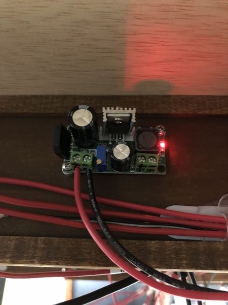
John, the buck converter is installed with 18VAC, waiting on the switch. Does it matter if I drop the output voltage below 12V to slow the speed of the TT motor?IMG_5980

Attachments

Images (1)
  • IMG_5980

Add Reply

Post

OGR Publishing, Inc., 1310 Eastside Centre Ct, Suite 6, Mountain Home, AR 72653
800-980-OGRR (6477)
www.ogaugerr.com

×
×
×
×
Link copied to your clipboard.
×
×