
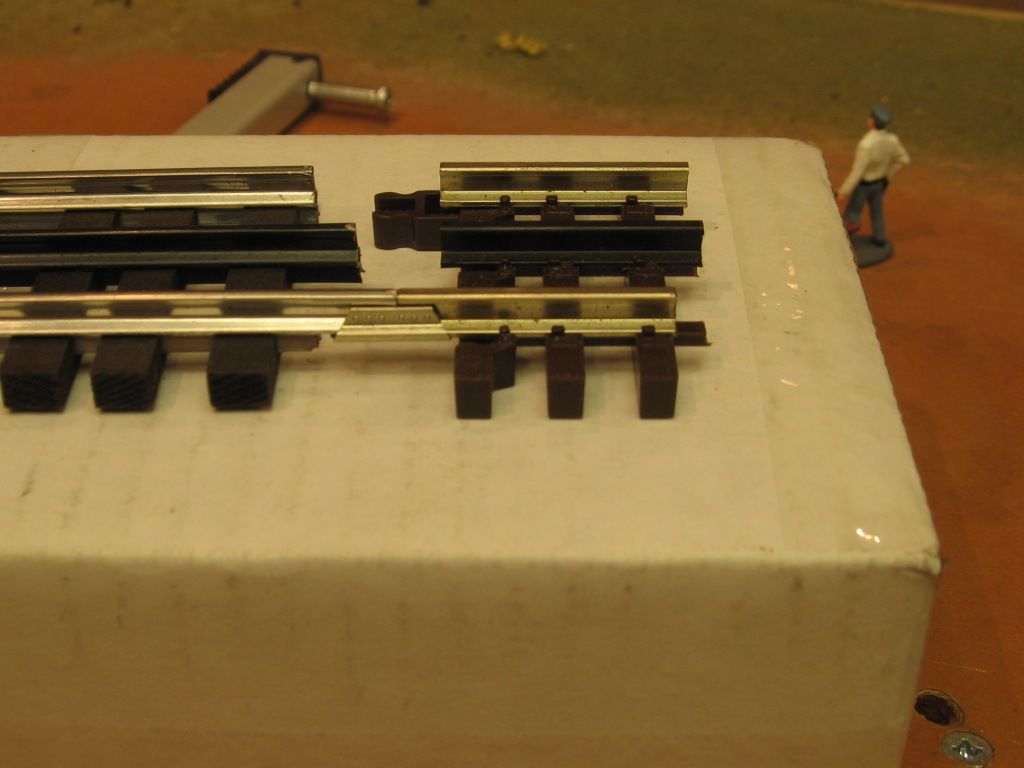
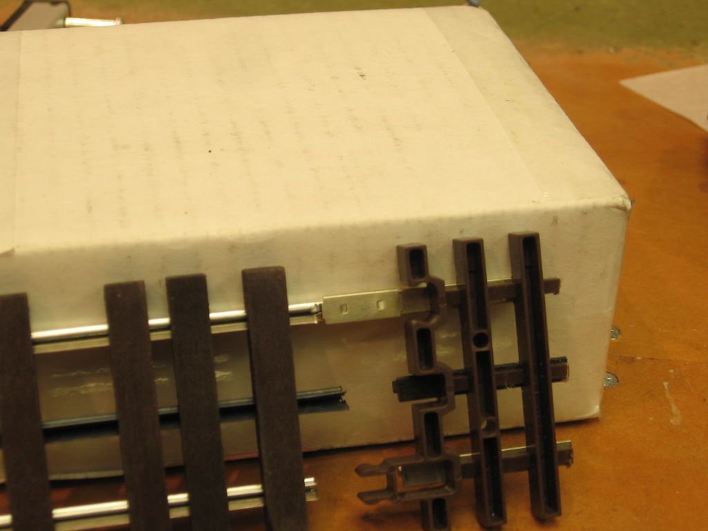
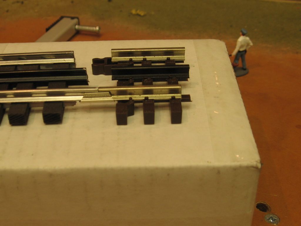
It seems that, when coupling Atlas track to Ross switches, or when adding Atlas uncouplers to Ross track, that the Atlas, flange mount, track joiners are a perfect fit.

So then, since it seems to be difficult to get Ross track tight together with the pins that have the small ridge in the center, why couldn't all of the ross track be joined with the Atlas flange joiners? Yes, I realize that the joiners would need to be shortened a bit to fit between the Ross ties, especially when using the Rossbed style roadbed, preventing adjustment of the ties.

I was thinking that, then, I could also use the atlas power drops in lieu of soldering wires to track at all of those locations. I could probably make my own Atlas style power drops a lot less inexpensively as well, and easier than soldering to the track. I realize that some areas would still need to be soldered, like non-derailing connections, etc., but it would cut down on track soldering by a large amount.

Am I missing something, or could this work?

Another option might be to still use the pins, but eith the addition of the Atlas style power drops.

Good idea, or not?

Last edited by RWL
Original Post

Replies sorted oldest to newest

MichRR714 posted:

Connecting track with pins is a much better connection.  All you need is a block of wood so you can tap the track home without damaging the track.

I have read that in several places  but when tapping the next piece of track in place, what are you tapping against at the other end?

RWL:

I routinely use Ross and Atlas O track together. If you plan on using Atlas rail joiners, rather then shortening the joiner (very time consuming) simply under cut the end rail on the Ross track. I use a small hand chisel to do this.

Ross to Atlas O 005

Other methods include a special Atlas O to Ross joiner - hard to use plus one poster warned me about using them for a reason I can't remember. You also have the choice of butting the ends together and applying power / ground to both sides.

Joe

Attachments

Images (1)
  • Ross to Atlas O 005
RWL posted:

Do uou guys just live eith the extra spacing between the ties?

And, what about the Atlas style power drops?

For me yes. I will use ballast so things get hidden pretty well. If you don't like the space you can purchase a Gargraves track fairly inexpensively and pull ties from it. I think they may even sell extra ties.

By Atlas power drop are you talking about the pre-wired joiners they sell? I have no problems with them but have standardized on split jaw connectors which I can use on either Ross or Atlas O track (but not on Gargraves). I use split jaw connectors mostly because I don't like soldering but soldering directly to track is a whole lot cheaper.

Split Jaw Connector 006Split Jaw Connector 005

Joe

Attachments

Images (2)
  • Split Jaw Connector 005
  • Split Jaw Connector 006

I would give the Atlas joiners a slight squeeze with pliers to tighten them up against the Ross/Gargraves track. As for the Atlas-style power drops, You can grind the bottom of a regular Atlas joiner and solder a wire to it (16-18 gauge) and they'll work fine. I'd apply conductive grease to the rails before installing the joiners to prevent oxidation from building up in the joint.

Model Structures posted:
RWL posted:

Do uou guys just live eith the extra spacing between the ties?

And, what about the Atlas style power drops?

For me yes. I will use ballast so things get hidden pretty well. If you don't like the space you can purchase a Gargraves track fairly inexpensively and pull ties from it. I think they may even sell extra ties.

By Atlas power drop are you talking about the pre-wired joiners they sell? I have no problems with them but have standardized on split jaw connectors which I can use on either Ross or Atlas O track (but not on Gargraves). I use split jaw connectors mostly because I don't like soldering but soldering directly to track is a whole lot cheaper.

Split Jaw Connector 006Split Jaw Connector 005

Joe

I have some of those connectors but haven't used them yet as I haven't laid any track yet. Life keeps getting in the way of finishing the table so that I can start.

I take it that you like these connectors well enough?

AGHRMatt posted:

I would give the Atlas joiners a slight squeeze with pliers to tighten them up against the Ross/Gargraves track. As for the Atlas-style power drops, You can grind the bottom of a regular Atlas joiner and solder a wire to it (16-18 gauge) and they'll work fine. I'd apply conductive grease to the rails before installing the joiners to prevent oxidation from building up in the joint.

I did mention in my original post that I could probably make them a lot cheaper than buying them, and easier than soldering to the track.

More curious about the effectiveness compared to soldering direct, since there are other connectors in a run of track anyway.

RWL posted:
AGHRMatt posted:

I would give the Atlas joiners a slight squeeze with pliers to tighten them up against the Ross/Gargraves track. As for the Atlas-style power drops, You can grind the bottom of a regular Atlas joiner and solder a wire to it (16-18 gauge) and they'll work fine. I'd apply conductive grease to the rails before installing the joiners to prevent oxidation from building up in the joint.

I did mention in my original post that I could probably make them a lot cheaper than buying them, and easier than soldering to the track.

More curious about the effectiveness compared to soldering direct, since there are other connectors in a run of track anyway.

Where the problem arises is the joiners seem to work loose/move around from the vibrations of the trains and from thermal expansion/contraction. While they keep the rails aligned, they can make for a weak electrical connection. Conductive grease helps that, but soldering directly to the rails is better.

RWL posted:
Model Structures posted:
RWL posted:

Do uou guys just live eith the extra spacing between the ties?

And, what about the Atlas style power drops?

For me yes. I will use ballast so things get hidden pretty well. If you don't like the space you can purchase a Gargraves track fairly inexpensively and pull ties from it. I think they may even sell extra ties.

By Atlas power drop are you talking about the pre-wired joiners they sell? I have no problems with them but have standardized on split jaw connectors which I can use on either Ross or Atlas O track (but not on Gargraves). I use split jaw connectors mostly because I don't like soldering but soldering directly to track is a whole lot cheaper.

Split Jaw Connector 006Split Jaw Connector 005

Joe

I have some of those connectors but haven't used them yet as I haven't laid any track yet. Life keeps getting in the way of finishing the table so that I can start.

I take it that you like these connectors well enough?

Yep - just remember if you purchase for Atlas O you need the version on the left that is shaved a wee bit. The standard version is too wide to fit inside Atlas O rails.

AGHRMatt posted:
RWL posted:
AGHRMatt posted:

I would give the Atlas joiners a slight squeeze with pliers to tighten them up against the Ross/Gargraves track. As for the Atlas-style power drops, You can grind the bottom of a regular Atlas joiner and solder a wire to it (16-18 gauge) and they'll work fine. I'd apply conductive grease to the rails before installing the joiners to prevent oxidation from building up in the joint.

I did mention in my original post that I could probably make them a lot cheaper than buying them, and easier than soldering to the track.

More curious about the effectiveness compared to soldering direct, since there are other connectors in a run of track anyway.

Where the problem arises is the joiners seem to work loose/move around from the vibrations of the trains and from thermal expansion/contraction. While they keep the rails aligned, they can make for a weak electrical connection. Conductive grease helps that, but soldering directly to the rails is better.

I agree

Joe

I do not like the pins with the  Ross / GG spacer tabs.  Rather annoying when running no sound equipment.   Every joint is an obnoxious  click on all wheels, IMO.  Even if you feather the leading edge of each rail it is less than desirable.   Three rail running is loud enough without that noise.

Because the thin tinplate rails are so easy to solder I will  use a smooth surface aligning pin which permits touching ends and drop a soldered lead to each piece of track/rail.  I simply drill a hole in the tie next to the rail, scuff it with a Dremel wheel, poke a color coordinated feeder drop in to it and tack it into place.  Goes very quickly.

Tom Tee posted:

I do not like the pins with the  Ross / GG spacer tabs.  Rather annoying when running no sound equipment.   Every joint is an obnoxious  click on all wheels, IMO.  Even if you feather the leading edge of each rail it is less than desirable.   Three rail running is loud enough without that noise.

Because the thin tinplate rails are so easy to solder I will  use a smooth surface aligning pin which permits touching ends and drop a soldered lead to each piece of track/rail.  I simply drill a hole in the tie next to the rail, scuff it with a Dremel wheel, poke a color coordinated feeder drop in to it and tack it into place.  Goes very quickly.

I am not sure I completely understand. Can you clarify this procedure a bit?

Thanks

Which part is unclear?

For smooth alignment pins I touch the side tabs of the Ross or GG pins on a grinding wheel or use friction fit spiral  shank coppers or piano wire and shove the  track together.  Some may disagree but my non sound 3 rail trains now run less the clicks.

Feeder attachment.  2 rail/3 rail the same.

8.17 026

Dremel #EZ456 cutoff disk on a shaft or 90 degree head to clean off the soldering spot. Just touch the base, don't kill it.  I can drill the holes, poke in the drops and solder the connections in less than a minute each.  First I drill all the holes then feed all the wire drops then solder all the connections.  Production run. maybe a half hour for 50 drops.

Bend a Z shape in the wire where it goes through the deck to help hold the tab end in place for soldering


Attachments

Images (1)
  • 8.17 026
Last edited by Tom Tee
MichRR714 posted:
RWL posted:

I have read that in several places  but when tapping the next piece of track in place, what are you tapping against at the other end?

The track I'm attaching to is typically already fastened to the table, and I never had any issues getting my Gargraves/Ross joints nice and tight.

That is how I pictured the process, but it seemed to me that the mounted track might get damaged or at least shifted out of pisition, from the pounding. It must take a lot lighter tapping than I had imagined.

How often, or at what spacing, do you attach your track to the table, and what do you use to attach it? Do you use the screws that Ross sells?

Last edited by RWL

RWL:

Both Ross and Atlas O sell track screws - I believe they are eqivalent to each other so it comes down to price and availability.

Track Screws - #4 3/4" Blackened Pan Head, Phillips (250 pcs). Price: $12.95

Atlas O 6094 Track Screws (48). Price $4.25

Ross seems a whole lot cheaper.

Where you lay screws is really up to you, track length and the 'levelness' of your train board. Basically you don't want track picking up from the board or wiggling side to side. Once you start you will get a feel for where to place screws.

Joe

William 1 posted:

Tap the Ross track together with a wood block.  You don’t have to leave a space between the rails.  Where did that come from?   A little elbow grease comes in handy.  Just push them together.  They will get as tight as can be.  

If you are referring to the "Leaving them a bit loose" statement, that was referring to the screws holding down the track. I plan to get the track pieces as tight together as possible.

Also, thanks for the encouragement on being able to get them together.

You can use the Atlas joiners with some finesse.  Gargraves, (left in picture), the below track profile, has to be removed, with a Dremel cutting tool/wheel.  Atlas,(right in picture).  The tie profile also needs to be shimmed/adjusted.  The Gargraves to Atlas transition connectors, were a bit flimsy.    IMO, Mike CT.

Track screws.  Atlas 2nd from the bottom.  Black flat head screw in the middle is Gargraves/Ross.  Both screws would require a pre-drilled hole in the tie.  Bottom group #2, Middle group #4, Top screws are #6, black is a #6 drywall screw.  Except for the black color most screws would be available at a local hardware store.

Last edited by Mike CT

Ted,

The rail joiners as seen in Mike's picture above are:  Atlas O 6091 (silver), 6092 (black), 6093 (insulated).  As mentioned, you need to cut a way the lower portion of the Gargraves track to make them work.  This is not required for Ross track, which is easier to attach to Atlas track.

There is also this rail joiner but it does not seem to make as good a connection.  I use the standard Atlas joiners above.

Atlas O 6096

ato6096

Attachments

Images (1)
  • ato6096

Add Reply

Post

OGR Publishing, Inc., 1310 Eastside Centre Ct, Suite 6, Mountain Home, AR 72653
800-980-OGRR (6477)
www.ogaugerr.com

×
×
×
×
Link copied to your clipboard.
×
×