Actually, it probably would be easy.  Simply remove the center wire from the switch motor; you leave leave it hanging..  If you use the 022 controllers, simply disconnect the middle wire from the 3-conductor running to the switch motor, and run a wire to it from the transformer grounds.  A single wire from the transformer ground (usually "U") can feed all of your controllers.

This eliminates the voltage loss, not only from the length of wire, but also from the train which is drawing current through the outer rail feed and the outer rails.

I should add:  What size wire is feeding the outside rails, and do you have frequent drops to feed the outside rails?

Last edited by RJR
stan2004 posted:

See this 8-year old OGR thread where member Bobby Ogage converts the #195 tower to LEDs.  Apparently it is not a straightforward task.  I did not find a concluding thread or consolidated how-to instructions so perhaps the project was abandoned?  If I understand the discussion from back then, Lionel re-designed the #195 to use LEDs so that might be the closest exit.

But it seems to me the issue of sluggish distant switches is still an issue?  As I stated earlier, the 1-2V drop on post A (14V, 0.5A) is much worse when the switch solenoid actually fires as the current jumps to a couple Amps.  If I understand your 18 ft answer to my distance question, that's 9 ft from ZW to distant switch and then another 9 ft from switch back to the lever controller near the ZW?  Hmm.  That should not be a problem if you had a "pure" 22ga connection over that distance.  But with connectors, splices, whatever who knows!  I don't know what's easy to try but some experiments could include, 1) temporarily running a test piece of 14ga (or whatever heavy gauge you have) directly from ZW post A to the distant switch, or 2) taking a spare lever controller and attaching  the 3-wire control cable with only a few inches of wire right at the distant switch.  The idea is to ferret out where the drop is coming from.  I may be getting ahead of myself here but I'm imagining some scheme to parallel a few strategically placed wire runs - much like the idea of wiring track voltage with multiple feeders.


Stan - all good info, thanks. I see now reading that thread that the reissues of the 195 had Christmas light bulbs in them, and there is a company on the Bay that sells an LED retrofit kit for those, so that might indeed be an option. 

I did a closer measurement on the 022 wiring and it turns out the longest run is 18’ for the power (due to the daisy chain) and about 12’ back to the controller. I’ll do the tests you suggest out but also love the idea of parallel wire runs to the switches - brilliant! So simple and I do it with track power, yet for some reason I would have never thought of it for the switches. Thanks so much!

RJR posted:

Actually, it probably would be easy.  Simply remove the center wire from the switch motor; you leave leave it hanging..  If you use the 022 controllers, simply disconnect the middle wire from the 3-conductor running to the switch motor, and run a wire to it from the transformer grounds.  A single wire from the transformer ground (usually "U") can feed all of your controllers.

This eliminates the voltage loss, not only from the length of wire, but also from the train which is drawing current through the outer rail feed and the outer rails.

I should add:  What size wire is feeding the outside rails, and do you have frequent drops to feed the outside rails?

Oh wow, that is a great idea! Very easy and I will just cut the middle wire short at the switch. Then, a couple of inches from the controller I will cut the center wire so as to leave enough room to splice on a new wire to run direct from the controller to U on the transformer. 

All track wire is 14ga and I have added many drops over time to even it out, both to center as well as outer rails and I run to both outer rails because of the Gargraves. 

Thanks for the great tip - can’t wait to try it out. 

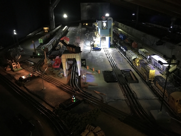
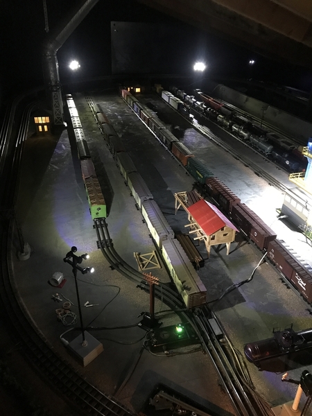
Hi all - this has been an interesting and educational process. Ultimately I decided that 4.7amps of draw just from lighting was more than I wanted, so I made a very easy LED conversion.

I decided to relieve my 2 195 towers (32 incandescent bulbs in total) and one of my 395 towers (4 bulbs). 

In their stead, I bought 4 Lemax LED towers (5 LEDs each tower at 80ma of draw at 4v) and use that now to light my yard. To complete the effect, I will also add a couple of #70 yard lights using LEDs I found that work well with them.

Outside the yard, I will retain one original 395 tower because I love the look, plus my 394 rotary beacon and a few incandescent street lights in the countryside and on the station platforms. 

Now measuring the current draw of the lighting on the ZW, I’m at 1.7a which I feel I can live with. It sure runs a lot cooler!

Here are a couple of shots of the yard. The color temperature of the LEDs is probably about 6k, reminiscent of the hue of sodium vapor lights you might see in a yard. Overall suits me just fine. 

A long way of saying, problem solved and thanks to everyone who weighed in and helped me out! 

C77B62B8-6A04-4F33-B9A8-C49B6BAE8103

94B6F071-DC7F-4A82-B412-33659EA705DB

Attachments

Images (2)
  • C77B62B8-6A04-4F33-B9A8-C49B6BAE8103
  • 94B6F071-DC7F-4A82-B412-33659EA705DB
Last edited by CoastsideKevin

Add Reply

Post

OGR Publishing, Inc., 1310 Eastside Centre Ct, Suite 6, Mountain Home, AR 72653
800-980-OGRR (6477)
www.ogaugerr.com

×
×
×
×
Link copied to your clipboard.
×
×