Hey guys,


I mentioned a project I am tinkering with in another post and I thought I would start a thread just for the build.


The project is to build a fully operational switcher type loco that is battery powered and WiFi operated with digital sound and PWM controllable LED lighting.


The parts and pieces:

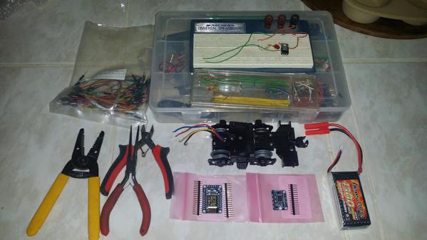
K-Line front powered DC drive truck from some random diesel loco.

Battery (for testing) 1300mAh LiPo 11.1V 3S1P.

(2) Microcontroller + WiFi Adafruit ESP8266 HUZZAH breakout boards. One for the layout and one for the loco.

Motor Driver Adafruit Stepper Breakout.

and a bunch of plastic, wood, glue and wires lol.


Lets clear up a misconception about WiFi - NO YOU DO NOT NEED THE INTERNET TO HAVE WIFI!

Sure, in some cases where you want to use an scripted website to control a WiFi device you do need an internet connection. In cases where you are using just the WiFi to run a device based program NO YOU DO NOT NEED THE INTERNET. All WiFi devices have the necessary protocol and hardware to talk to each other. Whew... I will be using a self scripted Android app to control this loco and layout with my handy dandy tablet and phone.


I have already had several friends pipe up and say "you can't use a stepper motor controller to control a DC motor..." Sheesh. Yes, you most certainly can. A DC motor controller is an H Bridge style controller and a DC Stepper motor controller is based on 4 half bridges where each half bridge controls one of the multiple winding's blah blah blah. For my test, I use two of the half bridges to create an H bridge for motor control. This leave two half bridges to control LED's and maybe a coupler, we will see.


If you are a total electronics noob, don't be intimidated by this little project. Here is a secret "an H bridge is just some switches...". Very oversimplified but true, four transistors make the main part of an H bridge driver. Transistors are a switch. 

Microcontrollers are a piece of cake. In this case the ESP8266 HUZZAH can be programmed with the simple Arduino IDE.


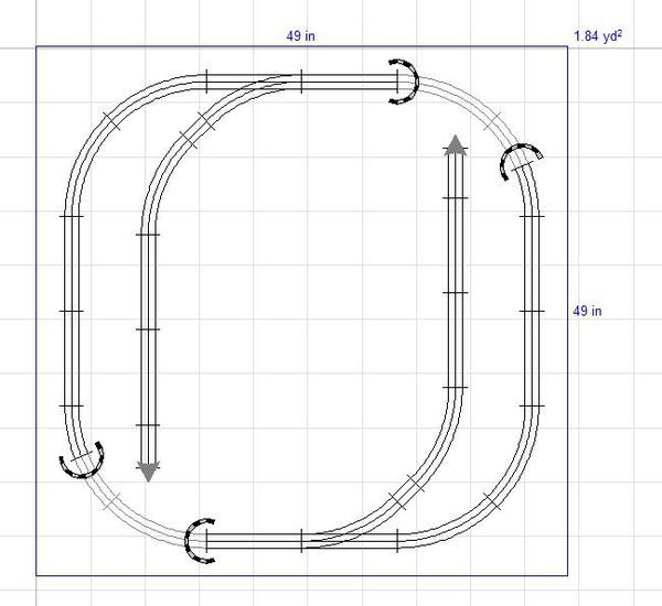
My plan - Control a train on dead O-27 track and control the lights and two switches on the little test layout. All of the O-27 track is slowly being crafted into two rail, wood tie O-27 (I know that will hurt a few minds) as are the two switches. I will show pics as I go.


The train parts 

WiFi Train


The mini 4X4 O-27 Layout 

WiFi Layout


I hope you follow along and if you have questions or comments, please post them.

Attachments

Images (2)
  • WiFi Train Parts: Some of the bits and pieces...
  • WiFi Layout: O-27 WiFi Layout
Original Post

Replies sorted oldest to newest

Thanks for following along. It won't be a quick process at first. Because the electronics and programming are fairly rudimentary and lol I lack a loco to mount them on, I will be building something that passes for a diesel critter (ISH).


Since I am building old school, you know... bits of plastic, glue and a razor knife the build part will be slow. 


The efforts of today were to get rid of any excess parts from the power truck and create something that passes for a chassis mount and coupler mounts.


Thanks for following along guys.


Ted


WiFi Stripped TopWiFi Chassis Supports 1

Attachments

Images (2)
  • WiFi Chassis Supports 1
  • WiFi Stripped Top
Last edited by 027Ted

Excellent Ted


I've re-powered my (8) 3-rail steamers to Battery-Powered, Remote-Control and removed all the 3-rail stuff from them, even pulled up the middle rail.  I'm using 9.6v 2000Mah NiMh and 11.1v 2200Mah LiPo battery packs from ALL-BATTERY and RC gear from RCS (Tony Walsham owner) in Australia.


I was looking at AdaFruit today, at their LED offerings, she has some cool stuff on her website.


I like the way you've mounted the motor


Keep us up to speed on your progress.

OH MAN I AM A DOPE...


So, I am gluing all of the pieces together to make a deck, front and rear pilots and the side frames. After an hour, I go check on progress and parts just fall over when the bracing is slid away. I think "what the h***" and start investigating.


I know I am working with polystyrene and Testors glue melts it together nicely... What I didn't realize is that the printing on once side of the plastic is not printed !*&#@%^&%$ it is a pressure adhesive sticker. A PVC based film which is impervious to model glue...


So, drop the five pieces apart and peel the !@#$%^&*( film off and I get to start over in the morning lol.


FWIW - I did test the glue before I started and it worked well. By happenstance I glued two raw sides together.


Ted

Last edited by 027Ted

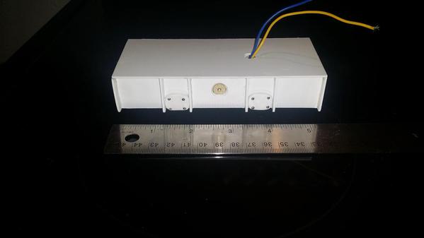
OK, after the false start yesterday with the coated plastic, I managed to build something that looks like a critter chassis.


Don't laugh to hard, a modeler I am not. Now, get me started with robotics and electronics...


I had to add a little gratuitous detail to the side frames. I don't think it looks too bad.

The motor stymied me for a bit but a hole for tip of the bell end and all fits well.


Now, for a shell.


Ted


WiFi Bottom

WiFi Top

Attachments

Images (2)
  • WiFi Bottom
  • WiFi Top
Last edited by 027Ted

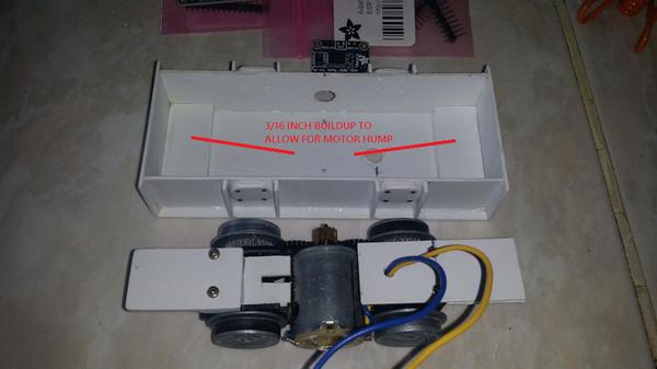
Here is a little more showing the mounting of the power truck to the chassis -


WiFI Chassis Buildup


The power tuck is held to the chassis with a couple of micro servo mounting screws.

WiFi Chassis Mount


To continue on, it is time to start figuring out where the brains of this operation will be located. The battery will end up in the engine compartment and the three boards (two shown) will be in the base of the cab. Both the hood and cab will be removable.


 WiFi Circuit Layout


I changed the amp on my OSounds board so I don't have the prototypes in to show location. Maybe in a couple of weeks... Basically, it will have to rest vertical against the back of the cab.


Ted

Attachments

Images (3)
  • WiFI Chassis Buildup
  • WiFi Chassis Mount
  • WiFi Circuit Layout
Last edited by 027Ted
Originally Posted by Bob Delbridge:

Ted,


I've got a .410 shotgun that should make all the holes you need


Hey, maybe you could make one of those work cars (and a trailer for the battery) the maintenance men used to ride around on:


railcar club

LOL I have a Benelli Super Nova Tactical loaded with 00 buck for coyotes... I just bet I could end my pain and blow a bunch of plastic all to heck!


I love those work cars. Be neat to find a plan and call it version two.


Ted

Hey guys,


I have not forgotten this... the wifey had other plans for my time. Mostly, jacking the old farmhouse sag out of the center of the basement.


Bob, 

-NiMH - Nope. When the energy density outpaces a LiPo then maybe.

-PWM - Yup, just as high as I can clock it.

-Battery - Using the time honored RC airplane method. Pop it out and recharge it. I am actually planning on using two RE magnets to hold the battery hatch (hood) on the chassis.


Ted

Ted,


I've got LiPos (11.1v 2200Mah) in 5 of my 8 steamers, the other 3 are 9.6v 2000Mah NiMh.


I read the internal resistance of the LiPos is lower than that of the NiMh, so you get a bit better voltage at startup (don't have to turn the speed knob on my TX7 as far), which to me is great for switching.


I also believe that lower than 9.6 volts would work fine too, unless you want a speed demon on your rails.  I haven't experimented with anything but the 2 mentioned above so I'm not at all sure what would be the lowest voltage to use.


With the way I have the RCS system currently setup I have to turn the knob more when using the 9.6v battery to get the engine moving than I do using the 11.1v (the Tx7 transmitter has 300 degrees of rotation).  I can re-program the startup voltage on each receiver, so a smaller turn of the knob (when using the 9.6v) will give me what I want, just haven't done it yet.


In other words, when using a 9.6v battery I have to turn the knob say, 40 degrees, to get the engine moving.  When using the 11.1v turning it 35 degrees gets the engine moving.


This isn't a big deal, unless you're visual perception of things is as anal as mine.  I expect the engine to move when I turn the knob a certain degree, when I hit that degree of turn and the engine doesn't move it bothers me for some reason.  The best way is to "just turn the knob" and watch when the engine starts moving and don't worry about how many degrees it's been turned.


The system I use is comprised of:


1-Transmitter

2-Receiver

3-Battery Pack

4-On/Off/Charging Jack module

5-Wiring

6-Charger


Seven of my engines have this basic setup, with power going to the DC can motor, headlight, backup light, no sound or smoke.  The 8th engine has a small module for connecting a sound card, I currently have a MyLocoSound card in this engine.  I've gotten used to having no sounds, although I do miss the chuff in the other 7.

Originally Posted by Bob Delbridge:


This isn't a big deal, unless you're visual perception of things is as anal as mine.  I expect the engine to move when I turn the knob a certain degree, when I hit that degree of turn and the engine doesn't move it bothers me for some reason.  The best way is to "just turn the knob" and watch when the engine starts moving and don't worry about how many degrees it's been turned.


LOL we must be related, Bob. Between anal retentiveness and a touch of OCD everything must work a certain way lol.
 
The nice thing about using a programmable interface is that I can indeed program the loco throttle to work relative to the control 'knob' where a traditional RC system is of a fixed relationship.
 
Here is my basic concept:
 
Lets say the throttle knob is a 1000ohm potentiometer. I can read the the output of the knob using the A2D port in decimal voltages. 0 volts = off and 5 volts is full throttle.
 
Using an 8 bit system that gives me a 0-255 range on the A2D port. The results could be as fine as about .0195 volt steps.
 
Start by bench testing the electronics to determine where the PWM starts the motor to spin on the track. It is important that this test be done with the full weight of the loco. We can call this value X. Now run it up to the highest PWM setting that will be used and call it Y.
 
Lets say that X is 1063 and Y is 2317 for example.
Now it is just simple math.
 
Y-X = R(range)
2317 - 1063 =  1254
 
So 1254 is our available PWM range. We already know that we have 256 steps available coming from the A2D port and if we wanted to use this range (ridiculous) and set the PWM accordingly. Personally, working in 100's is close enough so I would divide the R range by 100 = 12.54 and round to 13. Then divide the A2D port by 100 to get 2.55 and round down to 2. Now it is real easy... for every 2 A2D add 13 to the PWM. At the upper end of full throttle I would use a greater than case to clean up the rounded numbers. You will never see a speed difference.
 
This is a very simplified look and what is necessary to control a motor in relation to a knob and is not meant to be a programming tutorial. Keep in mind, weight of the consist will affect motion as well so all numbers should be adjusted to an average load.
 
Ted
 
 
Last edited by 027Ted

I'm at the point with my setups that I need to look at each engine and adjust (re-program) for optimal operation.  A couple of them work well enough, my MTH Railking Imperial 0-6-0 is working perfectly, but a couple of them could use a good tweaking.  I've got 2 Railking 2-8-0s, one works fine the other (with a new motor no less) doesn't.  I've never been one that agrees these things need a break-in period, but who knows.  Maybe the new motor needs just that, or there could be some burrs on the worm, or maybe alignment issues.  Just need to do some checking.


Turning the knob on my Tx7 transmitter/throttle isn't the same as scrolling the knob on the DCS handheld or twisting the big red knob on the CAB-1, it's hard to envision those 256 steps (the knob travels 300 degrees, so that's a bit over 1 degree per step).  I put a dial indicator under the knob with 10 degree increments, 0 to 100% turn of the knob.  I tell myself the throttle is set to 50% of power instead of XX mph.  If I need 60% to get up a slight incline, I simply crank it up!

Add Reply

Post

OGR Publishing, Inc., 1310 Eastside Centre Ct, Suite 6, Mountain Home, AR 72653
800-980-OGRR (6477)
www.ogaugerr.com

×
×
×
×
Link copied to your clipboard.
×
×