
I have always had an interest in heavy electric railroading.  Of course our beloved GG1 is still at the top of my list.  Lately I have been doing a bit of research on the Milwaukee road's electrification.  Mind you, nothing that most here do not already know, but now and then facts are unearthed that were not known previously, by yours truly in this case.  

I did not know about the non existence of gearing on these locomotives.  The way I read the article, the axles were the armatures.  In effect each powered axle was an electric motor.  I find that interesting.  It also seems that these locomotives had tremendous pulling power, but not the speed the Pennsy wanted for it's North East corridor.  I suspect gearing would help in that case.  If you read through the article, you'll see where General Electric claimed a 90 MPH top speed, but the Milwaukee Road set it at 70 MPH.  

It's also interesting to note the initial cost of each of these locos and the issue with the rebuilds.  

Here is the article from Wikipedia.  

"The Milwaukee Road's class EP-2 comprised five electric locomotives built by General Electric in 1919. They were often known as Bipolars, which referred to the bipolar electric motors they used. Among the most distinctive and powerful electric locomotives of their time, they epitomized the modernization of the Milwaukee Road. They came to symbolize the railroad during their nearly 40 years of use, and remain an enduring image of mainline electrification.
Design[edit]
In 1917, following the tremendous success of the 1915 electrification of the Mountain Division, the Milwaukee Road decided to proceed with electrifying the Coast Division. As part of this project it ordered five new electric locomotives from General Electric for $200,000 apiece. Their design was radically different from the boxcab locomotives previously provided by General Electric for the initial electrification of the Mountain Division two years earlier. The Milwaukee Road was the only railroad to order this design of locomotive from GE.
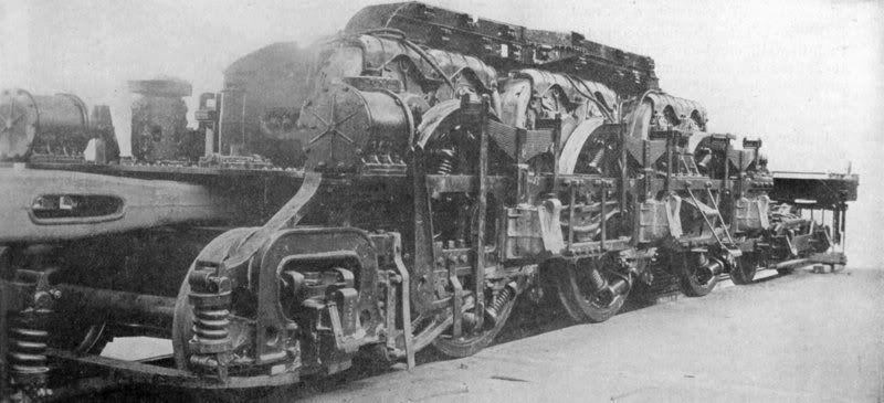
The most remarkable mechanical improvement was arguably the traction motors used on the new locomotives. They were known as bipolar motors, because each of the locomotive's 12 motors had only two field poles, mounted directly to the locomotive frame beside the axle. The motor armature was mounted directly on the axle, providing an entirely gearless design. This design was almost entirely noiseless, as it eliminated not only gear tooth growl, but also the whine of higher-RPM electric motors typically used in standard nose-mounted applications. The EP-2s were not the first electric locomotives to use bipolar motors, which had first been designed by Asa F. Batchelder for the New York Central S-motors over a decade earlier, but at the time they were the largest.
The layout of the bipolars was unusual as well. The locomotive carbody consisted of three sections. A small center section contained a boiler for heating passenger cars, while the larger end sections contained the locomotive's electrical equipment and operator cabs in distinctive round-topped hoods. The locomotive's frame was split into four sections, hinged at the joints, with the two middle sections attached to the end sections of the locomotive body. There were twelve sets of driving wheels, plus a single idler axle at each end, for a 1B-D+D-B1 wheel arrangement. All buffering forces were transmitted through the locomotive frame.
The bipolars were designed to be able to pull any Milwaukee Road passenger train singly, and were originally delivered without multiple unit controls. General Electric claimed a top speed of 90 mph (145 km/h) for the locomotives, but the Milwaukee Road rated them at 70 mph (113 km/h). They were rated at continuous 3,180 horsepower (2.37 MW) with a continuous tractive effort of 42,000 lbf (190 kN) and a starting tractive effort of 116,000 lbf (520 kN).
Service history[edit]

Milwaukee Road EP-2 "Bipolar" leaving Seattle, 1925.
When the Bipolars were introduced, their modernity and distinctive design made them the most famous of the Milwaukee Road's electric locomotives. They came to symbolize the Olympian, the railroad's premier train from Chicago to Seattle. Their unique appearance and power made them ideal for publicity purposes, and there was a series of demonstrations in which a Bipolar was able to out-pull contemporary steam locomotives. During a short period of testing on the Mountain Division, the EP-2s were shown to be less expensive to operate than the GE and Westinghouse electric locomotives then in use.
The five EP-2s, numbered 10250-10254, were placed into regular service in 1919 on the Coast Division. The Milwaukee Road saw immediate cost savings over the steam locomotives previously in use, as the Bipolars could run from Tacoma to Othello without stopping for servicing and could haul trains up grades that had required double-heading steam engines.

E-2 on display in 2008
The Bipolars operated on the Coast Division from 1919 to 1953, for most of that period without any serious rebuilding. In 1939 they were renumbered E1-E5. In 1953 all five of the EP-2s, which were 35 years old and worn out from heavy wartime service, were heavily rebuilt by the Milwaukee Road at a cost of about $40,000 per locomotive. The rebuild included additional traction motor shunts for increased speed, roller bearings, multiple unit capability, flash boilers, and streamlining. The E5, rebuilt in the Tacoma Shops as the prototype, performed as advertised, but went over budget, so the Milwaukee Shops were tasked with rebuilding the other four Bipolars. Unfortunately the Milwaukee Shop forces, unaccustomed to working on electric locomotives, did a "poor job" in the opinion of Electrification Department Head Laurence Wylie. (Wylie's successor, T. B. Kirk, stated that he saw a group of disconnected wires in a newly rebuilt EP-2 bundled together and tagged with a written message, "We don't know where these go".) Afterwards the Bipolars were prone to electrical fires and failures, despite repeated attempts by Tacoma Shops to correct them.
Between 1954 and 1957 the Bipolars saw decreased use, and in mid-1957 were transferred off the Coast Division to the Mountain Division. Their problems persisted; moreover, passenger train speeds in the Rockies (over 80 miles per hour or 129 km/h in some locations) were generally in excess of the Coast's top speed of 60–65 mph (97–105 km/h), further exacerbating these problems. Between 1958 and 1960 all five were gradually retired, by which time they had received the Union Pacific-inspired yellow and gray passenger paint scheme. In 1962 all except for E2 were towed to Seattle and scrapped. Locomotive E2 was donated to the Museum of Transportation in St. Louis, Missouri in 1962 and moved there that year. It has remained on static display ever since, and has been fully restored to its appearance immediately after its 1953 rebuilding."

Original Post

Replies sorted oldest to newest

It can always be done at lower cost by strictly limiting the allowed man-hours for the project, and therefore paying less attention to details that possibly might have paid off in better and more reliable performance.  It also helps if the shop doing the project for less money is finished with the locomotive after rebuilding, while a different shop is responsible for maintaining it and living with any shortcomings resulting from having been rebuilt at lower cost.

A capital project such as rebuilding of a locomotive, requires submission of a budget.  Sometimes revisions will allow going over budget if it was found to have been inadequate, as the first requirement is to get the budget approved, and this is sometimes done with full knowledge that supplemental funding will be required in order to finish the project.  Usually, it is granted, but -- as we see here -- not always.  There is internal political scheming inside of the Mechanical Department of any large railroad, and this certainly gives the appearance of one shop having seized an opportunity to grab a capital budget away from another.  In corporations, budgets give power.

Thus,  "T. B. Kirk, stated that he saw a group of disconnected wires in a newly rebuilt EP-2 bundled together and tagged with a written message, 'We don't know where these go'. Afterwards the Bipolars were prone to electrical fires and failures, despite repeated attempts by Tacoma Shops to correct them."

Last edited by Number 90
The GN Man posted:

I highly recommend the book "The Milwaukee Electrics" by Noel Holley. 

I second that excellent recommendation.  Noel has been interested in the Milwaukee electrification since he was a very young man.  He was able to meet many of the people, including Laurence Wylie himself, who made the equipment run as long and as well as it did.  Noel also had the opportunity to ride in the cab of several of the Milwaukee electric locomotives.   

Dick Steinheimer is the author of the other essential book on the Milwaukee electrification. 

As I recall, one or both of the books contains a photo of a Bi-polar under construction at Erie that shows the armature on the axle.

The Milwaukee EP-3s were very different.  Built by Westinghouse, they had two traction motors geared to each axle through quill drives.  Milwaukee engineers loved the speed and smooth ride of the EP-3s.  But they were difficult and expensive to maintain and the first class of electrics to be retired.

No, 3000 VDC was not unusual. I have an original EF-1 boxcab instruction book and the specified nominal voltage is 3000.  The substations along the line could vary the voltage according to specific needs including compensating for loads and line losses as well as specific equipment needs such as rotary snowplows. The catenary voltage typically varied from 1500 to 3000 volts at the pantographs, and the Bipolars, Quills, EF-1/2/3/5 boxcabs and Little Joes all worked fine. (The passenger engines came into Butte, MT under the Butte, Anaconda & Pacific wires at 1800V, which worked fine since it was a light, flat, low speed move.) 

PLCProf posted:

I am interested in the electrical design of locomotives such as this; it appears that they ran on a catenary at 3,000 VDC which is a difficult design for a motor of such dimensions. There are many ways to work around this, and I am curious to know exactly how it was done. Do the referenced books give an overview of the electricals in the Bipolars?

One obvious answer is that the rounded sheet metal hoods covered rotating machines that converted the 3000 VDC on the catenary to something more friendly to traction motors, but that is purely a guess on my part.

3000 volts DC was fairly common for railway electrification circa WW I.  It was obsolete by the middle third of the 20th century.

Noel Holley gives quite a bit of information about the electrical systems on all the classes of Milwaukee electrics.

The Milwaukee electrics used 1500 volt traction motors in pairs.  None used rotary converters on board as one of the advantages of a 3000 volt DC electrification was the ability to avoid such complications.

Commercial AC to 3000 volt DC rotary converters were used in the substations.

Ted Hikel posted:

3000 volts DC was fairly common for railway electrification circa WW I.  It was obsolete by the middle third of the 20th century... 

Commercial AC to 3000 volt DC rotary converters were used in the substations.

I remember a hobby magazine article years ago (maybe NMRA Bulletin?), someone built "operating substations" for their electric Milwaukee model railroad with electric motors to simulate the unique sound of a substation in operation. That could be an interesting feature for a model railroad depicting equipment of that vintage.

primrosestationandtrain

Because of the current limitations of the older substations and overhead wiring, the "Little Joe" electrics were not usually double-headed IIRC.

Attachments

Images (1)
  • primrosestationandtrain
Last edited by Ace
The GN Man posted:

Ace, the Little Joes were typically double headed (actually MU'ed), with a GP-9 in the consist as well. It's in the books that have been mentioned already. Boxcab sets as mid-train helpers were frequently used as well. 

Maybe what I meant was, they couldn't run more than two together because of the power supply limitations? I have the book "The Milwaukee Road" by Fred Hyde/CTC Board (somewhere).

Last edited by Ace

For most of the life of the electrification the Milwaukee usually made a complete power change at Harlowton, Avery and Othello.  In the mid 50s and early 60s that usually meant a "double Joe and a Sputnik."  After 1957 "Sputnik" was a slang term for a GP9 run from a lead Joe with a Wylie throttle. 

By the late 60s second generation road power ran through to Tacoma with single Joes added as extra power from Avery to Harlowton.

The little Joes taxed the capacity of the 1915 substations.  Air gaps on the rotary converters were decreased and output voltage raised to 3300 to try and meet the demands of the Joes.

>I remember a hobby magazine article years ago (maybe NMRA Bulletin?), someone built "operating substations" for their electric Milwaukee model railroad with electric motors to simulate the unique sound of a substation in operation. That could be an interesting feature for a model railroad depicting equipment of that vintage.

What might a sub-station have sounded like?


As I recall the Milwaukee substations there was the sound of a low speed blower moving lots of air; electrical hum, maybe 360 hz; and the sound of the brushes, a white static sound with maybe an occasional squeak. They were always clean and usually warm.  The sound level was high enough that you had to raise your voice to talk to someone else while in the machine room. There were three cottages beside the substation for the three operators to live in with their family.  Three men covered three shifts seven days a week, no days off. If an operator wanted to take a vacation a releaf operator was sent in.  He lived in the vacationing mans cottage while he was gone.  

Last edited by David Johnston

Don't think that this was explained before, but the reason for the "BiPolar" design was that because the armature was wound around the axle, itself, the axle had to have room to move up and down with the variations of track surfaces.  Obviously,  there would be no room for the axle and the armature windings to move if the field coils were surrounding the armature so the two fields were place in front of and in back of the armature, which then could make vertical movement without restriction.

I' aware that the NYC S-1, S-2 class steeple cabs were also "bipolar". designed by the same engineer, but does anyone know if there were other "bipolar" engines that had been built for electric service?  Be interesting to learn about other such builds.

As to voltage:  3,000 vdcwas rather high for electric RR service.  Other than the Milwaukee Road, the only other system of 3,000 volts was here in Cleveland on the CUT and when that system went down in 1953, one of the sub-stations was purchased by the Milwaukee road to increase it's capacity for the Little Joe operation.

Paul Fischer

Dominic Mazoch posted:

3000 V DC?  Was that not an "unusual" voltage for DC?  South Shore was at 1500.  Today Houston METRO uses 740 on LRT.  Is there something about multiples of 750 for DC voltage for DC electric operation?

The GN Man posted:

No, 3000 VDC was not unusual. I have an original EF-1 boxcab instruction book and the specified nominal voltage is 3000.  The substations along the line could vary the voltage according to specific needs including compensating for loads and line losses as well as specific equipment needs such as rotary snowplows. The catenary voltage typically varied from 1500 to 3000 volts at the pantographs, and the Bipolars, Quills, EF-1/2/3/5 boxcabs and Little Joes all worked fine. (The passenger engines came into Butte, MT under the Butte, Anaconda & Pacific wires at 1800V, which worked fine since it was a light, flat, low speed move.) 

Ted Hikel posted:

3000 volts DC was fairly common for railway electrification circa WW I.  It was obsolete by the middle third of the 20th century ...

3000v DC seems to be the highest voltage that was used for DC railway electrification, the advantage being to reduce the number of substations required on longer routes.

https://en.wikipedia.org/wiki/...ectrification_system

3 kV DC is used in Belgium, Italy, Spain, Poland, the northern Czech Republic, Slovakia, Slovenia, South Africa, Chile, and former Soviet Union countries (also using 25 kV 50 Hz AC). It was formerly used by the Milwaukee Road from Harlowton, Montana to Seattle-Tacoma, across the Continental Divide and including extensive branch and loop lines in Montana, and by the Delaware, Lackawanna & Western Railroad (now New Jersey Transit, converted to 25 kV AC) in the United States, and the Kolkata suburban railway (Bardhaman Main Line) in India, before it was converted to 25 kV 50 Hz AC.

fisch330 posted:
 

I' aware that the NYC S-1, S-2 class steeple cabs were also "bipolar". designed by the same engineer, but does anyone know if there were other "bipolar" engines that had been built for electric service?  Be interesting to learn about other such builds.

As to voltage:  3,000 vdcwas rather high for electric RR service.  Other than the Milwaukee Road, the only other system of 3,000 volts was here in Cleveland on the CUT and when that system went down in 1953, one of the sub-stations was purchased by the Milwaukee road to increase it's capacity for the Little Joe operation.

Paul Fischer

Paul

The NYC T Motors were also "Bi-Polars". 

3,000 volt DC electrification was fairly common the first quarter of the 20th century.  Several national railway systems in Europe electrified with 3,000 volt DC.  The Soviet Union made extensive use of 3,000 volt DC.  When the 20 'Little Joes" became undeliverable to the USSR in the late 1940s thanks to Stalin's attempt to force the western allies out of  Berlin the potential customer list was short.  They were too big for 3,000 volt railroads in Italy, Spain or Belgium.  Five of the Joes went to the 3,000 volt Paulista Railway in Brazil.  Three were converted to 1500 volts for the South Shore and the last dozen went to the Milwuakee.  Laurence Wylie had negotiated for all 20 and was offered a great price from GE.  But the Milwaukee board balked until the outbreak of the Korean war (thank you again Joe Stalin) brought increased traffic to the Milwaukee's Pacific extension.  By then eight of the 20 had been sold and the Milwaukee took the remaining 12 for the price they could have paid earlier for all 20.  

The Milwaukee did indeed buy rotary converter sets from the CUT and install them in Milwaukee substations to increase capacity for the Joes.  After WWII some Milwaukee substations also received remote controls so they could be operated manually from neighboring substations.  That was the big problem for 3,000 volt DC railroading with US freight tonnage.  Heavy US trains drew so many amps that substations were only a few dozen miles apart and, given the technology of the time, each had to be manually operated.  The continuous staffing requirement of substations in inaccessible  locations dictated the construction of three company houses next door for the operators and their families.  In effect, every Milwaukee train in electrified territory required the equivalent of a helper engineer to send power to the locomotives.  A good case could be made that the labor intensive Milwaukee electrification should have come down about the same time as the CUT.  GP9s were good road power and didn't need manned substations and linemen to maintain catenary.  Putting the money saved into the track would have helped the Milwaukee more than the fuel savings from 12 semi-modern electrics. 


Last edited by Ted Hikel

The Milwaukee used motor-generator sets for power conversion.  They were in the 1500 to 2000 kW range. There were two to three in each substation, usually with room to add more.  The oldest Mercury arc rectifier I saw was in the Valdez substation on the Sacramento Northern Railway.  It was a water jacked steel tank rectifier with twelve electrodes and one movable electrodes for striking an arc to vaporize the Mercury to get things started.  It was automatic, started on low voltage, shut off on low current.  According to a GE man I knew at the time, it was very troublesome.  He related stories of crawling around on the floor with a paint brush sweeping up the Mercury after one of many arc back incidents.

As I recall the Milwaukee raised the voltage at some point to 3300 volts. One of the short comings of DC electric railways was voltage drop. They kept pushing the voltage up to try and overcome this.  The Sacramento Northern was a 1200 VDC railroad and they went to 1500 volts and the Interurban Electeic Railway was a 1200 VDC operation and they went to 1300.  BART started out as a 1000 VDC railway and they are now at about 1225 VDC. 

One of the more interesting electric railways must have been the Michigan Electric, which for a while ran a 2400 VDC third rail operation.  William Middleton talks about an experiment with a 5000 VDC operation, but it never went anywhere.

After the Milwaukee gave up on the western end, the railroad I worked for at the time hired several of their engineers. Our locomotive superindent told me that they did not use dynamic braking, it was always air.  We had about 70 miles of 1% grade, ideal for dynamics.  I never learned why no dynamic operation, but I always assumed it had something to do with the electric operation on the Milwaukee. 

I believe the reason the Milwaukee ran electric operation as long as they did was they had a fixed price contract for the power. Once that contract price expired the electric operation was over.  

Last edited by David Johnston
David Johnston posted:

After the Milwaukee gave up on the western end, the railroad I worked for at the time hired several of their engineers. Our locomotive superindent told me that they did not use dynamic braking, it was always air.  We had about 70 miles of 1% grade, ideal for dynamics.  I never learned why no dynamic operation, but I always assumed it had something to do with the electric operation on the Milwaukee. 

Why throw away power as heat with dynamic braking when you can put it back on the wire and sell it to the power company with regenerative braking? 

Kelly:  That's a good question, for which I don't have an answer.   Maybe the armatures were "skew" wound and didn't have dead center.  In any case, with 12 motors on the locomotive, certainly several of the motors would not be on dead center.'

One other thing:  concerning the discussion on power conversion from AC to DC:  When the Milwaukee was electrified, it was common practice in electric railroading to use rotary converters to produce the DC at 600 volts.  The Milwaukee's intent to use 3,000 volts caused concern for insulation problems at the source.  The insulation available at the time and the design of the converters was not capable of handling that much voltage.  So the Milwaukee's DC power was developed by motor - generator sets with a 1,500 volt generator on each side of the central motor.  These generators were then connected in series to result in the 3,000 volts going to the trolley line.  They didn't use rectifiers anywhere on the system, I suspect, because no rectifiers had been developed for that high voltage.  

The amazing to me was that even in that early period of development of electric traction power, they were able to include the ability to regenerate power as motors were changed to regeneration.  This power actually flowed back through the trolley lines, through the motor - generator sets, and back to the power company.  That this system was being used in 1915 was very impressive to me.

Paul Fischer

Add Reply

Post

OGR Publishing, Inc., 1310 Eastside Centre Ct, Suite 6, Mountain Home, AR 72653
800-980-OGRR (6477)
www.ogaugerr.com

×
×
×
×
Link copied to your clipboard.
×
×