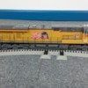
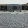
I have posted a picture below that will hopefully explain where the "black hole" dead spot is occurring.  In the picture it is between two switch tracks that are head to head or butt to butt, I'll let you decide, but it's where the switch lamp stands are located.

Take a look at the picture and you'll see an ES44AC MTH 2017 Union Pacific engine, then again, if BNSF were painted on it then it would be a BNSF engine, but hopefully to get te picture pardon the pun.  It is photographed sitting dead on the track, dead meaning it got that far at 5 miles per hour (smph) and just stopped then shut down without any commands from me or the remote.  I attempted some diagnostics.

I picked up the engine, moved it back to it's parking spot, started it up again, because at the spot it is pictured all I got was ENGINE NOT ON TRACK.  Once restarted I did a signal test at 3 miles per hour.  As the engine crept forward I saw 10,10,10,10,10,10, and when it reached said exact spot again, it went from 10 to dead.  Not 10 to 1 or 10 to 2 or even 10 to 0, it just stopped and shutdown.  Diagnostic 2.  I sped up the engine to 8 miles per hour.  From where it was parked, passed the dead zone, and on down the track I got consistent tens.  At that point I ended the signal test, used reverse to my advantage, and brought it back to the parking track at 6 miles per hour.  Tens across the board, including tens as it passed the black hole in reverse and parked itself, with my help and the DIR button.  I did a voltage test at 8 miles per hour.  Anywhere from 18 to 17.5 covering the same distance.  I did a voltage test at 5 miles per hour.  18 to 17.9 until it reached the dead spot.  Nothing.  Went from 17 point something, 8 I think, to completely stopped and shut down.  No extremely low voltage indication before it died.

Both switches work just fine.  They open on command, close on command, and minus a dead bulb on one of them, the left hand one, they work fine when commanded to dance.

The engine is brand new.  Maiden run last night right out of the box.  Four other engines on my layout that actively run over that same spot every day at 5 to 55 miles per hour and never miss a beat.  Problem first started with a DDA40X that I thought maybe the wide base between the trucks might be a cause.  This is a 19 1/2 ES44AC Premier just like it's counter part a 2016 version BNSF.  Same size, same length, same MTH.  I do have a 2018 RJ Corman SD40-2 that experienced a dead spot at the top of the track oval.  It did the same thing, stopped, shut down, sat 10 seconds, spontaneously started itself without my assistance, and reset all the defaults back to their original settings.  I knew because the smoke generator was on again.

The DDA40X has had all kinds of dead spot issues.  Even at 14 miles per hour it found one and shut down.

They only occur at areas of the track where multiple switch track are placed, and up to now, only three places where that occurs.  One is in the photo, two is where RJ suddenly lost consciousness, and a third is near an area where I have four switches set up to move a train from track 3 to track 2 to track 1.  Until DD stopped at 14, this poltergeist only showed itself when that particular engine was asked to navigate a switch or more specifically a set of switches at 5 or under miles per hour.  Anything 8 or above seemed to solve the problem.  A guy in Lexington told me it was due to "momentum".  Not dispelling his expertise, and I thank him for the advise, but how can going faster over a bad spot cause the engine to successfully overcome the bad spot?  To me that's like saying, if you walk into a wall, you'll hit the wall and break your face.  If you run real fast you'll pass right through it.  And I was upping the mph to 8, not 88.

The last scary moment in all this happened when I tried a final experiment.  I ran the engine at 6 mph over the same space and when it stopped, I quickly dialed up the speed to 10 or 12.  It didn't work.  BUUUUUUUTTTT, my BNSF engine, which by the way was on the inactive list at the time, suddenly woke up ready to run, moved forward at a slow rate of speed quickly picking up speed and was nearly at 20 before I could ALL STOP it and avert disaster.  Out of four inactive engines it picked that one, which by the way is number 1 on my list, UP is 2, and not only did it spontaneously start, but it took a life of its own and was running free of the remote.  Thank goodness the remote was still talking to the TIU so E STOP worked.

Does anyone out there have a clue what could be causing these "black holes", "dead spots", you are free to call them something else if you like.  But to answer a few questions I will probably get.

Yes I have read Barry's book.

Yes I did add booster wire drops to various parts of the ovals to increase and balance the voltage and signal readings.

I power my switches using the track not auxiliary power, but I did put chokes in each switch to help with that.  If you aren't sure what a choke is, ask Gunrunner John.

All of my engines are 2016-2018 MTH Proto-sound 3

I use Fastrack

072 left and right hand switches

The problem areas use Remote switches, not remote/command

I power my track using a lionel brick, attached to one of the fixed IN ports on my TIU and thus I have 16 gauge wire running from that ports OUT port to a Terminal Board where I have an abomination of 18 gauge wires hooked together that feed the track.

My switches all work off two AIU's and the remote.

Up to now I have had little to no problems with "glitches" after I followed everyones advice in December and ran the booster wires.

Any help anyone can give me on this is greatly appreciated

Attachments

Images (1)
  • black hole: dead in the water
Original Post

Replies sorted oldest to newest

PSAP2010

I checked the pickup wheels.  There are four of them.  Three have rollers that freely roll unabated.  The very front roller, the one nearest the cab, isn't rolling freely.  My guess is that it is scooting across the rail.  But the engine doesn't have any noticeable problems anywhere else on the track.

Rod Stewart

Great name by the way.  I'll check the distance on my other engines to see if they are closer together or further apart.  I'll especially check the BNSF engine since it is also an ES44AC.  But my question to that is why does the engine not stop and die at 8 miles per hour.  I can understand it compensating at 18 or 28 because the rollers are not on the dead spots long enough for the anomaly to take hold.  But 8? 

Thanks to both of you for your thoughts.  I'm going to look into the roller issue.  Even if it isn't causing this problem, scooting can't be good for it.


Try this:

Wipe the pick-up rollers with WD-40. Wipe most of that off.

Spray WD-40 inside the rollers, and roll them.  Wipe any running excess off.

Spray WD-40 on any roller hinge or spring joints.  Flex those joints.  Wipe excess off. 

Spray WD-40 on the wheel bearings.  Just enough to get some in there.  Wipe any WD-40 off the wheel surfaces very well. 

Wipe some WD-40 on your track dead spot.  Wipe that off.  Then, wipe the track with Goo Gone.  Wipe that off.  The track will be slippery until the Goo Gone dries, or you wipe all of it off. 

WD-40 promotes excellent electrical conductivity.   This process worked wonders on my home layout.  I didn't want to "spray" WD-40 anywhere near my trains or layout.  So, instead of spraying it:  I put some in a syringe and applied it to all the above places using the syringe.  

Rick

Yardmaster96 posted:

PSAP2010

I checked the pickup wheels.  There are four of them.  Three have rollers that freely roll unabated.  The very front roller, the one nearest the cab, isn't rolling freely.  My guess is that it is scooting across the rail.  But the engine doesn't have any noticeable problems anywhere else on the track.

Rod Stewart

Great name by the way.  I'll check the distance on my other engines to see if they are closer together or further apart.  I'll especially check the BNSF engine since it is also an ES44AC.  But my question to that is why does the engine not stop and die at 8 miles per hour.  I can understand it compensating at 18 or 28 because the rollers are not on the dead spots long enough for the anomaly to take hold.  But 8? 

Thanks to both of you for your thoughts.  I'm going to look into the roller issue.  Even if it isn't causing this problem, scooting can't be good for it.


Rod, I had several MTH engines, both SD70ACes and ES44ACs, that had the twisted pickup roller problem going through 2 O72 Fastrack switches with the turnouts opposed.  It usually occurred most often when going slowly from the turnout on one into the turnout of the other one.  

Thanks for the comment on my forum name.  PSAP is the reporting mark for the Puget Sound & Pacific, the local railroad, and the year I joined the OGR Forum.   The PSAP is part of Genesee & Wyoming, so I see a lot of orange, yellow and black engines in downtown Shelton. 


Larry

Last edited by PSAP2010
Rod Stewart posted:

Could be a roller spacing issue. If they both hit a spot where there is no center rail power at the same time (like with two head to head switches); bingo. Dead. Very common 3 rail track problem.

Rod

Dead on. Pun intended. Also, you won’t see the dead spot at speed cause it happens so fast the engine doesn’t react fast enough to shut down. Can you try putting a small section or straight track between the switches? At least fix the roller that does not spin freely. Keep us posted. 

I am so glad I talked to you guys.  Ok, here is what I discovered just a few minutes ago.  I took the 2016 BNSF AC and set it on the track exactly where the UP AC sits when it isn't running.  I fired it up, 5 miles per hour, let it stroll out through the two switches in the same direction the UP goes, and it did just fine.  No dead spot issues.

Took the BNSF, off, turned it over, measured the distance between the farthest rear roller arm wheel and the front most roller arm wheel.  It came to 14 1/4 inches.

Did the same thing with the UP, it stopped, turned it over, took the photo I promised Bobby D, and measured.  14 1/2 inches.  The 2017 version has the rollers located in such a way that the back most and front most touch the switch in different places than the 2016.  If that's the case, then based on what Rod Stewart and Rod Miller are saying, this could be an issue.  I checked the distance between the two rollers on the DDA and it came to 12 3/8 inches.  The DDA only has two center rail rollers, both located at the front most portion of the truck assemblies.  The two ES44's have four center rail rollers, two on the front truck, two on the back.  It appears, going with the Rod's theory, since the two switches are back to back, when the 44 and the DD begin their travel from the parking track to the "yard track" as I call it, the rollers are set just right for a problem.  Somehow, even though its rollers span a wider area than the 2016 version, all of the power rollers are caught in a dead spot at that point.  Even though the 2016 versions rollers cover a quarter inch less space, a roller is maintaining contact with a live area long enough for the other rollers to make contact with one and keep the engine alive until it can finish navigating the switch and get onto live straight track.

I have no clue if any of what I just said has any plausible fact to it, but the only thing I take from everything I just typed is this?

Why the heck is Lionel allowing track pieces to be designed with dead spots?  My feeling is that when you connect a track piece to another track piece, the electricity should flow from one rail to another seamlessly.  If there are internal wires or connections that block the flow of electricity from one center rail through the other to the next track piece, then find it, fix it, and eliminate it.  Meanwhile I have a $465 engine that I have to allow for a kink in the design of a track piece to run it.  Looks like parking track five will have to become the BNSF parking track, and parking track one will have to become the UP parking track to make peace with this.  I'll have to experiment and see where I can slowly exit and enter with the UP engine without the evil of dead spots.

If anyone else has a theory, suggestion or solution, I'm all ears.  I paid way too much for all this stuff to have quirks in the machine that the manufacturer can eliminate if they will just quit trying to save a buck and do it.  If the dead spots are my fault, then please, offer up any suggestions for me to eliminate them.  Adding a 1 3/8 piece between the two tracks might just do it, but understand, that means finding a 1 3/8 piece to eliminate at some other point.  Keep in mind, I do have a complete set of 3 ovals hooked together by switch tracks and making that happen required creative spacing problems and to fix them.

I'll let you know how it all works out.

Attachments

Images (2)
  • black hole under
  • black hole

Yardmaster, I can think of at least two other options.  First, can the roller pickup arms, or if necessary, the whole truck block from the BNSF be installed on the new UP loco?  If you could get these parts from MTH, this would get you back to the workable spacing of 14 1/4".  Second, you could try another brand of switch like Atlas O or Ross.  Perhaps the "dead spots" on other brands of switches are spaced differently.

Many recent Lionel locos have at least three, and sometimes four rollers.  Recent steam switchers have a power conductor (wire tether) between the loco & tender.  Lionel learned their lesson and doesn't take this for granted!

There are other threads on this forum that discuss adding extra rollers to the tenders on MTH steam locos.  In complex operating environments, two rollers just isn't enough.  The problem was exacerbated with a move to PS3 because apparently PS3 locos don't coast at all if power is lost.  This is also discussed in other threads on the forum.  MTH needs to get the message that using fewer rollers isn't a smart way to cut costs.

A third option would be to add a pickup to a boxcar, or "dummy unit" and a tether back to the loco.  You would always have the boxcar or dummy coupled behind the loco to ensure a constant flow of power.  Frustrating, I'm sure.  My $.02.

Last edited by Ted S

Just to know if the common is being lost, does the UP have the traction tires on the same side for both trucks? The trucks are sitting where the control rails for non-derail are located, but it would require that the traction tires are on opposite sides.

In the photo, it's the short curved rail on the left rear and the short straight rail on the front right.

Going a little faster is one option - investigating replacing the single collectors with a double collector would be another solution if it's the center rail issue.

Last edited by Moonman

Without knowing/seeing the underbody side by side we don't know the rubber tire/steel wheel issue.

Not having any of these switches, it looks to me your UP example has one entire side of each truck on dead rails. When you add in the center axles are not flanged so we don't know what type of contact they are making and another axle has rubber tires you are left with only 2 wheels, one on each truck, to complete the circuit. 

An easy 😂 way (guess that should read "another":-) to see if it is the rollers would be remove the shell and add a jumper wire between the center rail and the loco positive. 

Back to back switches are always a crap shoot because of so many dead rails built in to avoid shorts when changing routes and the auto switching feature when coming in from the legs.

Last edited by BobbyD

Just woke up.  Thought I'd check my replies.  Great stuff.  I read every one of them in detail.

Bob - I'm a greenhorn when it comes to the maintenance.  How to I add power to the loco in such a  way as to turn it over and look at the bottom of the loco?  Power is generated through the track as it sits on the wheels.  Again, greenhorn.

Bobby - All good stuff.  I will look at the trucks again this morning to see exactly which wheels have rubber traction tires and let you know.

For everyone's updated information.  This particular MTH loco has four pickup wheel assemblies.  Two on each truck.  As mentioned before, the 2016 model has a 14 1/4 back to front spacing, where the 2017, the one in question, has a 14 1/2 which seems to be the issue when a back to back attachment is confronted.  I learned last night a very important lesson about switch track in that dead spots are not only "dead spots", meaning spoken in gest, but real.  They are built in for safety to keep the engines from being fried.  One reply from last night mentioned MTH lack of coasting ability.  You're exactly right on that.  They don't.  When that engine reaches the "dead zone", it stops immediately, and the obvious lack of power input shuts down any PS3 cool engine sounds on demand.  So no, they don't coast.  They do hiccup.  I ran UP over the suspect zone last night at 8 smph, and as soon as that sweet spot hit the dead spot it "twitched" but kept going.  9 smph it never missed a beat.  I don't know if the truck assemblies are interchangeable but I'll investigate it.  Both engines are 19 1/2 long but when you match them toe to toe you can see that the pickup wheels have been reconfigured.

One last thing that may throw a wrench in this or help, I hope for the best in all cases.  The two back to back switches are Remote, not Remote/Command.  Why do I care?  I have four Remote/Command right hand switches that make up a "snake" system that lets the trains exit from the outer most track to the inner most track.  From outer to inner, all four switches are interconnected, no 1 3/8 or 1 3/4 bridge track separating them.  I ran the UP through one way at 9 and it did fine.  I backed it through the other way at 5 and it did fine.  On the opposite side of the room, I have just the standard Remote switches, no programming possible.  I ran it through one way at 9, did fine, but at 5, as it reached the mid point between the outer track and track 2, it stopped between the two switches at the exact same spot it stops in the picture I sent.  What was so cool about it is that I said, "NOW" just a split second before it stopped.  You can set your watch by this phenomenon.

I have an answer to the question regarding the rubber tires.  As you look at the bottom of the engine from cab to rear, I am numbering the wheels from 1-12.  In this case, on both the 2017 and 2016 versions, wheels 5 and 6 on the front truck and 11 and 12 on the rear truck have rubber tires.  3 and 4, 9 and 10 are those special kind of solid wheels used for.....tracking?   Honestly folks I don't know what they are used for, it doesn't appear to be electrical pickup.  But other than those four oddball wheels, the rest are the typical cupped metal wheels designed to imitate what we see on trains today. 

I'm a little late to the party on this one, lol, but here is an easy way to conclusively determine if you are losing power or ground in a situation like this. Grab an ohmmeter and proceed as follows.

First, on the engine, check the continuity from each wheel to the others. Note that in some cases, not all wheels are in the ground path (by design) - you need to know that as well. This check verifies that the ground paths within the loco itself are sound. It's also a good idea to check all the pickup rollers with respect to each other, although it is not strictly necessary for this test. Fix any issues before proceeding.

Now run the loco until it stops at the trouble spot, then power off your layout. With the ohmmeter, check the continuity of a grounded wheel (which you verified above) to the ground rail of the track. I use a clip on one lead to the track ground, and then touch the side or rim of the wheel with a normal probe.

If you don't see continuity, you are losing ground. If you see continuity, you've shown that you have ground, and are therefore losing power instead.

Set it to measure resistance (ohms), and look for a low value. An ohm or two would indicate good continuity. Some meters also have a dedicated continuity test, which gives a tone in the case of a low resistance. This is very handy for something like this, since you don't have to look at the meter.

Great ideas in this thread!

I've had a problem like this before and it drove me batty.  In my case, the solution was a loss of ground through the truck.  I cleaned the wheels and the axles, added a bit of conductive grease and that solved it.  How I arrived at that was by using a voltmeter during the stall state on each wheel.  Also, I found it helpful to slowly turn the loco on it's side and checking/marking the exact position of the rollers & wheels and their contact area on the track (or frog).

On another similar issue, it turned out to be roller distance incompatible with unpowered areas of the Fastrack switch.  Luckily my layout was flexible enough to add a small bit of track in between the switches to widen out the crossover.  That solved that issue.

Another item:  I have noticed that some modern Diesel engine trucks do not always tolerate even slight warpage in the table or floor.  Note the carpet seam between your switches.  Often those seams follow a natural high spot in the subfloor.  Try shimming one switch up slightly with thin cardboard and retest. Then try the other like that.  I've seen it work!   

I hope this helps a bit.

Last edited by Volphin

If the trucks are designed where as you can unscrew a mounting plate to remove a wheel set then something that has worked for me is to switch the 1st and 3rd wheelset on the truck. Now you have changed the traction tire placement allowing for the ground to pass thru. Where the tire once hit the ground area you now have a metal wheel allowing the ground to pass thru. This is assuming that both wheel sets have the same gear arrangement. 

You guys are great.  Adding track is almost out of the question.  Would hate to have to put in the time and effort only to discover that didn't work either.

I can run it at 9, and it overcomes the problem.  Why it navigates the R/C switches at 5 and not the standard remotes I have no clue.  At least I have options.

Not changing the subject but a sidebar if I may.  I set my accel and decel rate to 1.  When I press the boost rocker button and hold it down, it increases as follows.  6 7 8 10.  Every time.  3 singles then doubles.  Quirk in the DCS software or designed that way?

Yardmaster96 posted:

Carl.  Thanks my friend but I did that in December.   All 18 have one on the aux power side in place of the jumper.  

Good move!

So, we still have a finicky engine. 

Have you determined if it is losing power or signal?  I would have made a virtual square around that interchange and made that a DCS block. A few tracks away from all four legs of those switches there should be a 1 3/8" track or a 5" block track with the center rail jumper removed to isolate the interchange. Then, a hot and common to one of the THRU legs of a switch.

The DCS signal can also become unusable if you have multiple signal supplies converging on this interchange. Multiple signals are out of sync and confuse the engine.

I am assuming that you created blocks throughout the layout.

What I did was took the 2016 version of the ES44AC MTH in question, the one the works without stopping, and did a signal check with it, and a voltage test.  When I ran that one through during the signal test, I got 10's across the board into, through, and out of the switch headed for glory down the track with 10's galore.  Then I did the voltage test and got anywhere from 18 to 17.5 into, through, and down the track beyond.

As for the blocks, if you are talking about running tons of wire from my operations point to various parts of each oval and balancing the power output to the sides, back and front of the ovals plus parking tracks, yes, I did do that.  But as for 1 3/8 pieces having isolated rails, no, but I did have to use those pieces to connect the track at some points because I ran into the nasty problem of math and having fixed length pieces.  A handsaw was not possible.

I'm almost sure that the location of the pickup wheels is the cause because the 2016 version has the very back and very front wheel, of the four located under it, 14 1/4 inches apart.  The problem child has his 14 1/2.  So guessing, because of this, the front one and the back one and the two in the middle are all finding dead spots at the same moment.  Seems odd.  You'd think even if the back one and front one were on dead spots, the two in the middle would take up the slack and power the engine.  I'm gonna do a visual test tonight and see where each wheel is resting when the stop occurs. 

I have a question needing clarity you say you measured roller spacing front to back so do you mean from the first power roller at front of engine to the very last power roller on the last truck at rear of engine? 

seeing you know exactly where dead spot is take one engine and set on exact spot mark where power rollers are contacting the center rail and do the same for the engine having the dead spot issue if the engine having issue shows power rollers are on center rail prior and after switch points check the rails for power also check the rails in between the switch ends that are back to back do you have power on center rail as well as both ground rails this will eliminate a power to track issue.

lastly turn problem engine upside down or in a engine cradle or in lay it in between your legs and if you have alligator clip jumper wires for testing touch the power wire to each and every roller both trucks and the other to a wheel on engine for ground if you find one truck not getting power your issue is with most likely a power wire to rollers that is not connected broken or?

I hope this helps in narrowing the exact issue. I am not familiar with fast track switches so not sure how all is wired within them as built or if strictly those contacts on all rails when snapped together.

Last edited by StPaul

One more thing to think about... Is the offending loco a "Proto 3-2" convertible?  Is the loco that works NOT Proto 3-2??

I don't own any Proto 3-2 diesels.  But on MTH Proto 3-2 steam, wheels on opposite sides may be insulated from each other, which could translate to worse pickup on the ground side of the circuit, compared to locos made without this feature.  It's not a deal breaker, because ground wires from the two sides could probably be tied together internally with some minor rewiring.

Not saying this is the cause, but it might be something to think about.

Last edited by Ted S

The description didn't say anything about it being converted.  After some more experimenting, I think we have ourselves a pick up wheel issue.  I ran all four of my other engines through the same switch the same direction at the same 5 smph speed, and all four never missed a beat.  I looked under the UP engine and the pick up wheels are set where they are set.  They can't be moved forward, backward, or side to side.  If it is an off set issue, bending it is the only way to set it back where it should have been.  Not fond of that route.

I feel that if it were a power issue with the track, all five engines would be having trouble navigating the switch at low speed.  UP still hiccups or twitches when it goes over it in 8 or better speed.  But it does go over it without stopping.

I so much appreciate everyone's input.  I hope this thread helps someone else figure out why they are having the same problem.  I learned a lot too.  I also discovered the front pick up wheel has a flaw in it.  Trying to find a new one.  Easy enough to fix if I can get a new one.  One screw, magnetic screwdriver, pray I don't screw it up.

If possible I would like to know if anyone else has noticed that the acceleration rate jumps to a multiple of 2 even though it is set to 1 on the DCS.  Not a problem, but you'd think 1 means 1 regardless of how long you hold down the Boost button.

Yardmaster96 posted:

  I looked under the UP engine and the pick up wheels are set where they are set.  They can't be moved forward, backward, or side to side.  If it is an off set issue, bending it is the only way to set it back where it should have been.  Not fond of that route.

Sometimes you can remove the pickup roller mount, rotate it 180 degrees, and reinstall it. This will move the roller a good 1/2 to 3/4 of an inch inward or outward, changing how they line up on the turnout.

I cannot tell from your photo if this is feasible. The main thing is that you don't want the roller bottoming out on the truck.

30 seconds with a philips screwdriver and its worth a shot.  You could rotate a couple if need be.

Last edited by RickO

After looking at the bottom, I'm 90% sure this loco is one of the Proto 3-2 convertibles.  You should tie all the ground pickups (wheel feeds) together internally.  Doing so definitely can't hurt, unless you're planning to occasionally run it on 2-rail track.

Now you're saying your 2016 loco is also an ES44AC.  From the outside (cosmetically), does it have the same trucks and frame?  If so, I would get a pair of model year 2016 truck blocks and pickup rollers from MTH parts.  Install them on your 2017 loco, and maybe resell the 2017 parts to recover your cost.  The spacing should revert to 14 1/4" as on the 2016 model, and it won't stall anymore.  My $.02.

If you posted the actual product number of the problem loco in this thread, I didn't notice it.  But I googled "2017 MTH Premier ES44AC," and Proto 3-2 is one of the features listed.  I was already suspicious because (1) most MTH Premier diesels are convertible; and, (2) that aluminum or copper strip on the outside of the truck probably carries current picked up from one side of the loco to the stack of circuit boards inside.  The strip is needed because on a 2-rail loco, the truck block itself probably isn't grounded (or it's grounded to only one side.)

I understand why MTH implemented this feature.  But it throws away one of the inherent advantages of 3-rail trains- a robust ground pickup and mechanical design (metal wheels on a metal axle, running through a metal frame.)  As a consumer, you can undo most of the harm by wiring the grounds from both sides together internally.

It might be instructive to show the undersides of both locos (2016 & 2017) close-up side-by-side.  Whatever design changes were implemented with the 2017 model didn't help you.  So maybe you can just reverse them, at your cost, by substituting 2016 parts.  How much you'll have to swap is anyone's guess, all the way back to putting your 2017 plastic shell on a 2016 chassis.  The parts dept., and auction sites are your friend ;-)

Last edited by Ted S

Add Reply

Post

OGR Publishing, Inc., 1310 Eastside Centre Ct, Suite 6, Mountain Home, AR 72653
800-980-OGRR (6477)
www.ogaugerr.com

×
×
×
×
Link copied to your clipboard.
×
×