
Hello members, 

Just joined the organization and hoping to get some guidance for block system recommendations for Lionel postwar set up.  During the early 90s, I started using the Right of Way Industries (Row) solution that features a 3PDT system.  I really liked the prototypical aspect, particularly the 3 zone; (full sp, slow and stop zones), however the firm has gone under.

Is it worth resurrecting this system, or are there newer and better solutions with the same or similar effect?  If the RoW solution is not recommended please give rationale.  However, I am fully open to suggestion. 

Using Gargraves/Ross hardware, 6x12' layout dual track outer loop (same direction) and inside loop (opposite direction) that connects to the outer and inner loops, thus serves as a reversing feature.  I would like to operate multiple trains, based on planned block length, 3-4 simultaneously.

Thanks in advance for your expert advice.

Ray


Original Post

Replies sorted oldest to newest

Z-Stuff has a good set, Atlas O, has a good set, MTH has a nice set, NJ International has a good set. I actually chose the Atlas O signal system which works with Custom Signals. I think Lionel offers one to. You can pull these block signal systems up on your computer with lots of information for one that suits you. I preferred Atlas O, utilizing the outside insulated rail. Good luck. Happy Railroading 

If you have all of the parts needed use them.  Just because they aren't open anymore doesn't mean they don't work.  I personally like the three zone control.  Dallee made a detector that senses the current and can cause the signals behind to fall appropriately.  Red in block, slow block behind, and clear block behind that.  Do you need instructions for setting it up?  I don't know if @Lou N would have any insight in the signalling system.

Gene Anstine

Hello Gene,

Thanks for the response.  Yes, I like the system and have the relays....I think I have the relay connections wired correctly, but don't recall the where they go on the track.  I am using ZW for 24V power for the relays and another Z for separate zone 1, and step down for zone 2. 

The 3PDT relays are wired thus:

Terminals 1-2 pole 1, 4, 7, 8, pole 2 Note: terminals 1-2 are connected by a common. 

I can't determine which of the terminals on the relay is ground; Tried.  So yes if you can shoot me a diagram.  

Thanks,


Ray


Thanks for reaching out, Chief.  Hope you are doing well.

RayR....

I designed the circuit inside the ROW signals.  The company that made them also makes Hot Wheels and Matchbox.  It was a very interesting trip to the Orient.  Anyway, its just a timer to give about 4 seconds of YELLOW before going to GREEN.  It did create a satisfactory illusion.  The signal with timer circuit was copied many times and some of the best versions and widest variety come from MTH.  RoW signals still appear regularly on eBay.  MTH signals are still available.  

Please keep in mind that the Atlas signals are much more detailed and the control board can be arranged to be a R-Y-G timer circuit.  With the control board you can also invoke flashing yellow and flashing green.  The new version of their board is available now.  Please note that I am a member of the Atlas Signal Design Team.  I can answer questions about that product line also.

Your layout description sounds like it would lend itself to some control panels known as cTc model boards, like the tower operators used.

Lou N


Hello Lou and thanks for info.  I am open to any suggestions.  Given what i have described, what system do you recommend?  If the Atlas system will give me the 3 zone operation (nominal speed, slow and stop), I am certainly open to it.  The layout is quite small and I don't envision running more than four trains simultaneously on the mains, and perhaps independent action in two separate sidings.  

I don't think cost would be an issue.  I would like blocks integrated with main switches and of course signaling.  If you can provide rough material list, let's cost it out.  

I have attached a schematic for your review.

Attachments

Images (1)
  • initialplan

Ray,

Lou N contacted me in regards to your layout build. He mentioned your interest in setting up signals to work with the design you made. It would be easier to get started with a quick call to get the basics covered. You can reach me at  908-687-0880 Ext 7142 or email me  shorvath@atlasrr.com. If I miss your call please leave a good reach telephone number and time to call.

Thanks

Steve H

Ray, when you say "blocks integrated with main switches" does this mean automatic control mode works even with switch(es) thrown to transfer a consist between main loops?  In such a case, how is arbitration done if two consists (one from each loop) would be merging?  Or when switches are thrown then automatic control mode is disabled and it turns to manual operation?

Separately, if no one comes forward with wiring instructions to resurrect your existing 3PDT system, there might be some info gleaned from this OGR thread where member Chris A uses 3PDT relays in a DIY signaling system.  Here's a photo hijack from that thread suggesting it's quite the exercise in wiring. 

DSC06884

Each signal requires 1 3PDT relay which is/was about $3 each with screw-terminal connections (no soldering).  Block voltage control was not discussed in that thread but if needed that would be as "simple" as adding a pair of $1 relays controlled by the R-Y-G signal output to choose full-voltage, reduced-voltage, or no-voltage.  For example, 

 block power full-reduced-off relay control

Note that this 2-relay method allows application of a non-zero "stopping" voltage.  For example, on MTH PS2 or PS3 engines, if you apply ~7V to the track, the engine will stop but lights and sounds will continue.

So that would be about $5 per block to control a 3-aspect signal and apply the appropriate track voltage.  I realize you're less concerned about cost, but maybe useful as a data point to frame the problem.

Attachments

Images (2)
  • DSC06884
  • block power full-reduced-off relay control
Last edited by stan2004

Hello Stan,

These are all questions that need to be answered.  I guess one of the more simple solutions is to limit ATC to each loop and manually switch consists from one loop to another.  This fine, as  I don't need to get elaborate for the sake of it.  

Am I correct in interpreting your comments as inferring there are two or more means of control?  Example One, the signals control the block power and train movement, or Two, the train location dictates block power and signaling?  If that is not correct, what are the control system options, including advantages and disadvantages given the current size of the layout? 

The only 'requirement' is the three step block sequence vs. a go/stop which seems more realistic to me.  I am not fixed on the 3pdt solution either if there is another way to achieve this preference.

The solution you provided looks interesting, I assume switching is manual with the solution.  Looks fine to me...If based on the above, this is a good fit for what I want to accomplish, can we discuss in more detail?  Meantime, I will look over the control board function.

Thanks,

Ray

You guys are working well on a great solution to RayR’s model signal problem.

If you would like a little primer on real signals, CLICK HERE. Choose the signal aspect you want to see from the choices at the bottom of the screen and the main screen will show you what that signal aspect means.

Some additional info:

  • Limited Speed = 45 mph
  • Medium Speed = 30 mph
  • Slow Speed = varies by railroad, but often set at 15 mph.

Note that real signals provide a lot more information to an engineer beyond Normal speed, slow speed and stop zones. 

Last edited by Rich Melvin

Hi Ray,

To be clear, I approach this from a nuts-and-bolts ground-up perspective.  I am ignorant of the big-picture of prototypical signaling, ctc, and so on.  That is, in the linked thread someone inquired about the 3PDT method and I took it at face value.  That said, perhaps this clarifies my way of thinking:

signaling and block atc

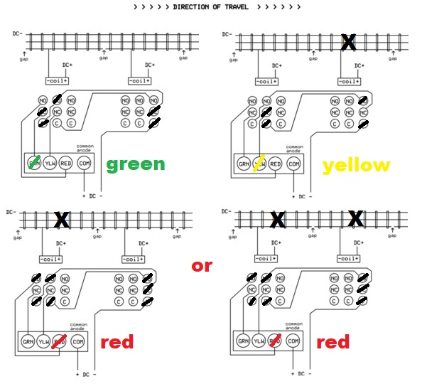
I believe this is what you call Example Two.  The train positions determine the signaling output.  The electronics or smarts to convert the occupancy detection information into R-Y-G signal output is performed using 3PDT relays (as used by member Chris A).  Per the above diagram, this function is the bedrock.

Then, if desired, the ATC function can be built onto the signaling function.  The ATC electronics is also performed with relays.

The diagram shows the R-Y-G signal for, say, block N.  The R-Y-G color is a function of the occupancy in block N and block N+1.  The ATC function takes the R-Y-G state and steers the appropriate track voltage to block N-1 which is before the signal.

This would be the bare-bones configuration.  Then the bells-and-whistles creep in!  I was studying some of Rich's real signaling.  In one case it suggests if a consist is going over a switch, you want reduced speed operation even if it's clear track ahead.  Makes sense to me.  So now you would add another input to the occupancy detection electronics to "force" the Yellow signal state whenever the switch is in the diverge position near the signal.  There are obviously dozens of conditions that might affect the signals if you want the two main loops "interacting" with each other when the switches are set to move consists between the loops.  If you are willing to keep the 2 main loops independent with respect to signaling, I'd think that was the easiest and the 3PDT method gets the job done.  Otherwise the sky's the limit on complexity and probably best to go with an off-the-shelf system that supports whatever complex interactions you want.

Same thinking with the ATC.  If you only use the normal-reduced-stop speeds, then a few dollars in relays per block gets the job done.  As Rich points out, real trains might have up to 5 (or probably more!) speeds of operation.  I'd have to think about how to practically implement something like that when you have a dozen or more total zones!  But if content with the bare-bones ATC, then I'd see a single toggle switch that would turn the ATC on/off to all the blocks in the loop.  When ON, the ATC would control train speed by applying zero, reduced, or full voltage to the N-1 block.  When OFF (for switching between loops), the ATC would simply apply, say, the NORMAL voltage to all blocks and you would manually control train speed until the correct trains on on the correct loops...and flip the ATC switch to ON and back to automatic operation.  Note that even with ATC turned OFF, the signals still "work" with respect to the occupancy conditions of the loop.

Attachments

Images (1)
  • signaling and block atc
Last edited by stan2004

Ray,  not sure if you checked out the other thread that Stan referred to above.   I followed Stan's 3PDT relay scheme so that I could have a RYG three aspect signal system that pretty closely followed the way the B&O Color Position Light (CPL) system worked.   It looks ahead 2 blocks and reports aspect based on train occupancy in the next two forward looking blocks.    

The wiring got a "little intense", as I have 11 blocks on a 240 foot main line, and I decided to intall signals for traffic in both directions.... so 22 signal heads,  22 relays...   I did not pursue automatic train control as I run Legacy and TMCC control so I have 17 to 18 VAC on the track at all times.   But I am very pleased with the results and it works exactly as Stan described it would.   Thanks Stan very much for the schematic do this. 

Here are some photos..... 

 DSC06909 [2)DSC06914DSC06913DSC06915DSC06917DSC06916

Attachments

Images (6)
  • DSC06909 (2)
  • DSC06914
  • DSC06913
  • DSC06915
  • DSC06917
  • DSC06916

Greetings Chris, 

Impressive, and based on what you have described appears compatible with my desired concept.  What i need eventually, is how to wire  the relays correctly to related connections.  I don't understand how the relay connections and contactors (on/off) send the correct signal (voltage) to the track and corresponding signal (lamp voltage) to the signals. 

I see unidirectional signaling on my simple layout for the time being and perhaps a speed reduction signal through the turnouts.  On the mainlines, there are only two single cross-overs and three single switches, so maybe adding that feature that may not overly complicate things. If so, that will be for my heirs to decide...

Thoughts?


R


Ray,  I'd suggest 2 things.....  First, I would do a google search for 12 VDC  DPDT relay operation, you should find a couple of links that will explain how these work in simple terms so you can increase your understanding of NO/NC contacts, and solenoid operation.   Using "insulated rail sections" essentially acts like closing a switch when the train enters the insulated block and the metal wheel/axle assembly connects the insulated rail to the other "common" rail, that is what energizes the solenoid and moves the contactor from NC to NO open state....  I know there are some decent "beginner introduction materials and videos" for Relays on the internet.  

Once that part is clearer, go to the other signalling thread that Stan2004 referenced above and see his post from Jan 2020..... He took the wiring diagram for the 3PDT relay set up and "marked it up" showing how the signal lights are triggered based on train occupancy so hopefully that will close the loop on how and when the Red/Yellow/Green aspects are energized/illuminated.   

I copied Stan's "marked up drawing", but I'd recommend going to the other thread to read the post.   

Ray, I realize this was last century but did the RoW 3PDT system perform BOTH signaling (drive a R-Y-G signal( AND apply the proper full-reduced-stop voltage for ATC?  And this was done with 1 3PDT relay per signal?

To be clear, the 3PDT configuration Chris worked on is just for the signaling.  As I showed earlier you would need to add a two relays to each R-Y-G signal to additionally provide ATC.  I realize you are seeking additional documentation of the RoW method but I would be curious to see how they did it!

Hey Stan,


Thanks for putting the passage of time in perspective...whoa!  my recollection is only the track control because i do not recall any reference to a second relay.  Given the simplicity of this layout, i would love to add the signaling option.  I looked everywhere for the old instructions and could not find them.

I am all-in on whatever contemporary solution is practical and workable for this application.  I would like to use the lionel overhead gantry signals if possible, but not an absolute must. I am using the prewired Ross switches as well.  Would the lionel coupling and accessory tracks impact operation?  If so, I guess I will need to put them exclusively in the sidings.

Let me see if understand how to set this system up.  If i can understand the logic, I could try a test block once I have procured the materials. I have plenty of wiring and terminal strips, but need new relays.

Note I was planning to use ZWs, but that is also not a requirement.  Any other considerations?


kind regards,


Ray


Ray,  I can address one of your concerns....   Yes the pre-wired Ross Switches will cause problems with the isolated rail set up... I learned this the hard way.   If a pre-wired switch is located in a block, the outside rails of the switch are connected by a jumper under the rails.  Took a while before I realized that the block was appearing to be "occupied" due to the outside common rail jumpers in the switch. 

 In most locations I drilled through the connecting strap as I didn't want to pull up the switch, and I didn't really want to cut another gap through the rail on both sides of the switch.  In one location I did chose to cut more gaps in the rail with the dremel wheel.   

I don't know about operating tracks, but take a meter and test for continuity between the outside rails,  on an operating track if you have one that's not installed.   


RayR posted:

...

I am all-in on whatever contemporary solution is practical and workable for this application.  I would like to use the lionel overhead gantry signals if possible, but not an absolute must. I am using the prewired Ross switches as well.  ...

Ray, do you have a part number on the overhead signals?  I admit I didn't try hard but when searching I only came across those that had 2-aspect red-green only signal heads.  I'd like to confirm there are 4-wires (1 common, 1-each per color) and nothing unusual...like common being welded to the metal bridge frame or whatever.  Also, do you know if the signal head can operate on 12V DC; this could be a big win with one alternative I'm pondering.

Chris, is there an "output" signal from a prewired Ross switch that electrically indicates the switch position?  Or does one tap into the lever-controller and if so how?  That is, I'm wondering if there's a simple way to detect an upcoming diverging switch to then force the signal to Yellow; as mentioned earlier I'd think the receiving track might force its signal approaching the switch to Red in anticipation of the consist from the other track?

Chris,,, I m tutoring myself on relay operation...I was familiar with the operating principle, but not how to comprehend and set up a logical circuit with a desired function, in particular when the circuit is not simple to me such as the block control circuit...will keep at it...

We'll have to find a solution for the Ross switches, or a work around....i would to see how the block and signal circuits are merged.  That can come later when i get the signal circuit operation...at this point this is visually more comprehensible than the block.

Ray,  about the switch position on a Ross pre-wired switch...   I don't believe that a "pre-wired" ross switch, as delivered from Ross will provide any output indicating switch position... Having said that,  if you are using the DZ1000 switch machine, or the DZ2500 switch machine, there is a DZ1008 relay which can be used to create an output indicating switch position, through the SPDT relay contacts...

Here is a link to the Z-Stuff web site describing the DZ1008 relay.   

If you elect to use Tortoise Slow motion switch machines they come with SPDT relay's built in, 2 sets of them, that can do the same thing as the DZ relay.

There have been threads for other methods using magnetic reed switches that will detect frog position, I read some of them briefly but never got motivated to buy and install them, there is some work involved.  

Hello Stan,


The lionel accessory is a #450 signal bridge.  These are only two colors and two leads which are wired to a pressure switch located under the track and activated by a passing train.  Its no big deal to substitute it, I actually prefer consistent three color signals for the entire layout, as well as a consistent signaling scheme. There is also a similar single track overhead bridge fyi.

Attachments

Images (1)
  • lionel450

This will surely confuse matters but here's an alternative to the 3PDT relay method using low-cost relay modules from eBay/Asia.  The basic idea is to use 2 SPDT relays to perform the function of 1 3PDT relay for the occupancy detection and signaling function.  So here what 3 adjacent blocks might look like.  Each block requires 2 relays of the SPDT type.

idea 2x spdt instead of 3pdt

Here's the equivalent diagram (compare to previous 3PDT version) showing which relay terminals carry the DC- voltage for the various occupancy cases.  It may be easier to follow the "logic" of this method vs. the 3PDT method.

idea 2x spdt for 3 aspect signal

Here's one implementation using stuff I had lying around.  I only had a 4-channel relay module handy so only 2 of the 4 relays are being used.

idea 2x spdt

For example, the unused 2 relays could be the 2 relay for the next block.  Or an 8-relay module could perform the signaling for 4 blocks.  There are 2-relay modules also for about the same $ per relay.

And here it is in action!


Attachments

Images (3)
  • idea 2x spdt instead of 3pdt
  • idea 2x spdt for 3 aspect signal
  • idea 2x spdt

GRJ, I don't know the genesis of the "original solution."  That is, Chris asked some questions about adapting the specific 3PDT relay method shown below and I answered his questions at face-value.  

blocksignalschematic

Obviously the 3PDT method "works" as demonstrated in Chris' layout.

But to your point, yes, if it can be done with 2 SPDT relays per block, one would think it could be done with 1 DPDT relay per block.

Attachments

Images (1)
  • blocksignalschematic

Gents,


I have received an Atlas solution for the signaling that will suffice for the layout. Based on comments received so far, integrating signaling to Ross Switches appears to be a nightmare so I can discount that.

However, what i seek is an integrated solution that includes the block control and signaling as a single package.  I don't care what the block control solution is.  So would someone be willing (for a fee) assemble a plan for this layout, including operating concept, materials list, and detailed assembly instructions.

If interested, feel free to contact me @rlrubio1@gmail.com.

Thanks and Happy Easter!

R

Ray,  there are some other important criteria you should be calculating no matter what final system design you settle on.   If you have already done this analysis sorry for wasting your time..... 

You need to set up parameters for average and longest train length you plan to run, and then make your block lengths some safety factor above that length.   This will be even more important if you are going to have the blocks controlling the operation of the trains.   If a train is longer than your block length, (ie. the train is occupying 2 blocks simultaneously),  on a regular basis this could cause alot of stopping and starting unless you have a really long main line....

I purchased one of the Kalmbach books "How to Build Realistic Layouts" it has an entire chapter about Signalling systems  ABS, ABP, &  CTC systems....   how and where to place signals and layout blocks.....  It's a good resource.  


Hi Chris, thanks for the heads up.  Yes, the layout design accounts for a standard block length,  Due to the size of the layout, this will compromise train length, but that is an unfortunate side effect.  The outer block length is approx 72 inches/5 blocks, and the inner block consists of 4 blocks a bit longer than 72 inches.  See attached diagram with signaling plan.  Note the dotted route section is under the table.

Attachments

Files (1)

I also built own signals and signal system for my layout.  In the end, it works well, looks great, but it was quite effort and took me over a year to complete.  The link in my post below shows the construction and circuits .

Shortly after completing my signals, I worked with my dad to install a complete signal system on his layout (over 500 square feet and roughly 30 signals) using atlas/ custom signals ( minus a CTC panel) from Terry C.. and it took only two weekends once the blocks and rails to be used for the signal system were decided on (the final design that planned for rail isolation to compliment power feeds to run trains took the most time). The custom signals solution is such a nice solution.  It is well thought out, where it is adaptable, has excellent terminal connections  and his pre made libraries really simplify the thought process.   I highly recommend this route!!!  If was to do another signal system on my own again, I would use the atlas/custom signals solution.

Dad’s layout uses over 15 Ross switches tied to the signal system with Dz1000s and dz1008 relay adapters for switch position indication.  If the signals must work with switch indications, I would recommend investing the time to understand how the Ross switches are wired with regards to power rails and non derailing as you will likely have the same issues with other switch manufacturers regardless of how you do your signals. 

I had never tackled the ATS solution, sounds like a fun adventure.

Last edited by Hump Yard Mike
chris a posted:
I purchased one of the Kalmbach books "How to Build Realistic Layouts" it has an entire chapter about Signalling systems  ABS, ABP, &  CTC systems....   how and where to place signals and layout blocks.....  It's a good resource.  


Chris-

I'm studying signals myself right now.  Which exact edition of "How to Build Realistic Layouts" are you referring to.  It looks like there are multiple versions available.

Tim

Add Reply

Post

OGR Publishing, Inc., 1310 Eastside Centre Ct, Suite 6, Mountain Home, AR 72653
800-980-OGRR (6477)
www.ogaugerr.com

×
×
×
×
Link copied to your clipboard.
×
×