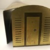
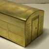
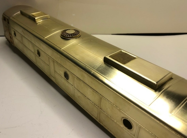
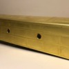
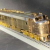
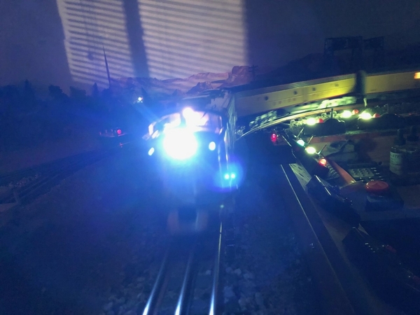
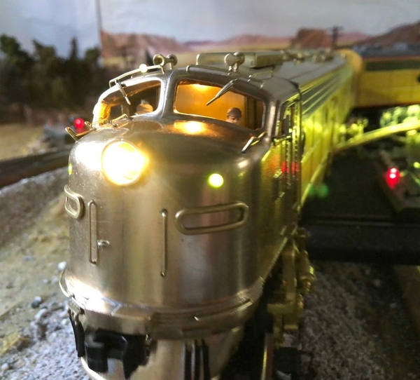
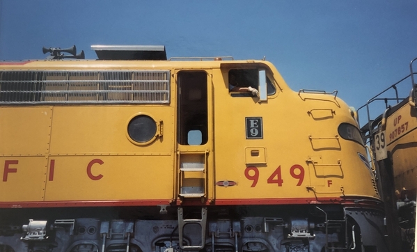
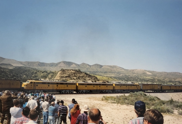
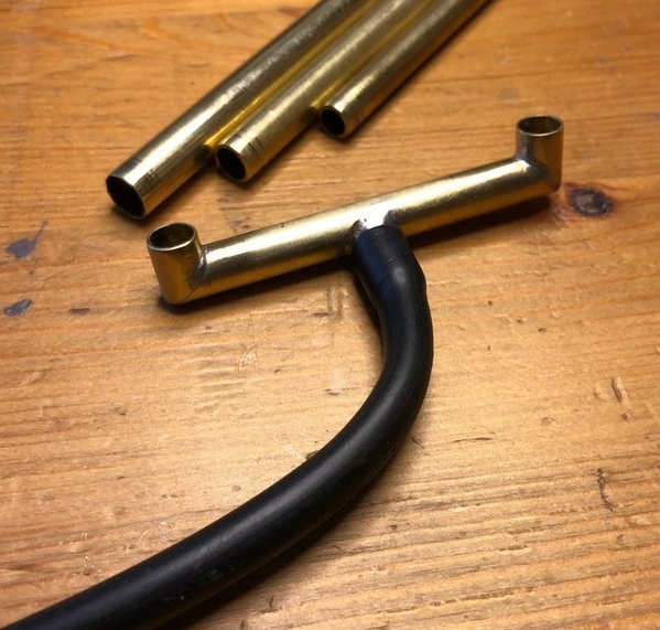
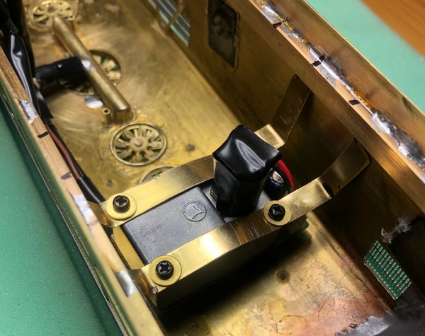
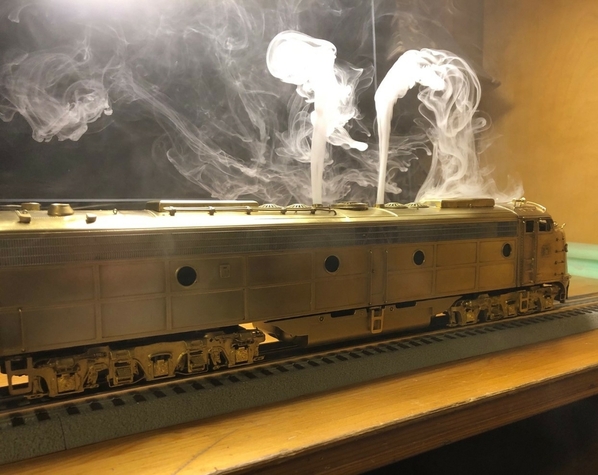
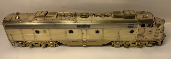
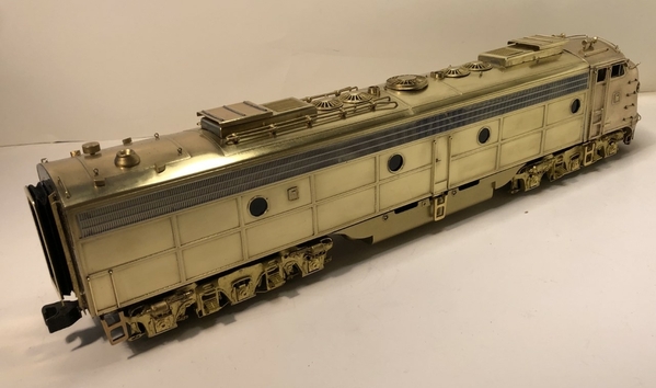
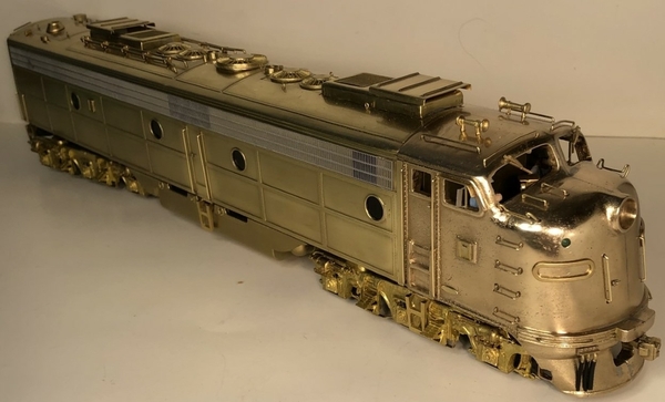
In this multi-part post I'll take you along the adventure of building a Locomotive Workshop's E9 kit.  Interest in building a locomotive kit occurred after I signed up to be a digital subscriber to O Gauge Magazine.  Alan Arnold has given us access to an incredible research tool and I would recommend all forum members sign-up to be an OGR digital subscriber.  I began reading these early OSR magazines cover-to-cover to learn more about our hobby.  Starting at issue #1, I learned of the different obstacles facing model railroad hobbyists at the time.   It seems during the late 60’s and early 70’s O scale trains were going through rough time.  The HO train market was getting huge and taking over the hobby.   There wasn’t a lot of O scale manufactures at the time and only a few of them made scale locomotives.  50 years ago if somebody in our hobby wanted a true "scale sized" diesel locomotive in a specific style or paint scheme, they had to build it.

By the time I hit OSR magazine issue #14, I read an advertisement that stated Locomotive Workshop was going to have an E9 diesel kit available in the near future for $59.50.  The ad's description read:  The E9 kit was sold basically complete except for the mechanism.  Includes basic body and soft metal trucks.  Brass engraved - photo engraved brass - brass photo etched body.  The nose section on this E9 kit was a lost wax brass casting.   

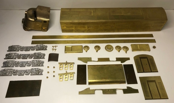
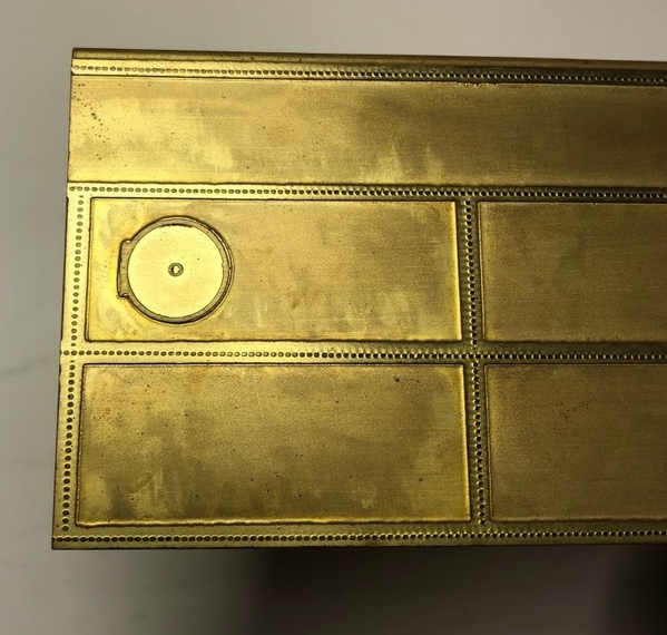
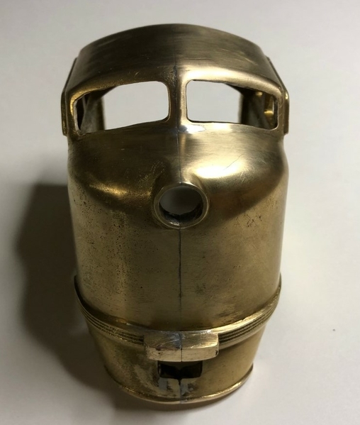
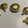
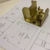
For me, building an unassembled locomotive from a kit was a completely different aspect of the model railroading hobby.  Ok then... I was willing to give it a try.  Looking online I found an unbuilt Locomotive Workshop E9 kit for sale and clicked Buy-Now.  The kit arrived at my house a few days later.  Here's what the parts look like laid out across a table.

thumbnail_IMG_9156


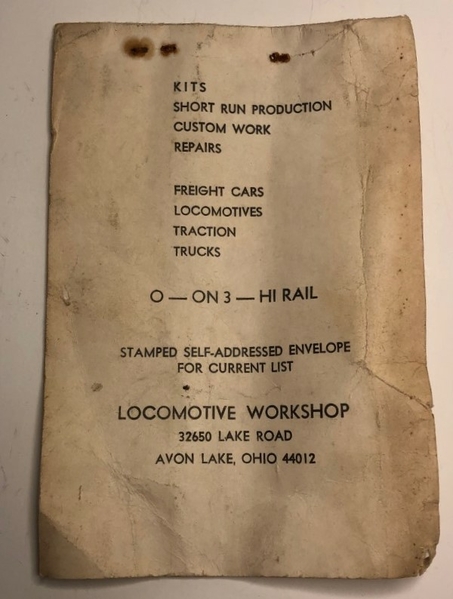
The literature that came with this kit said it could be built as O – ON3 – Hi Rail.  I decided to try and build this E9 diesel locomotive for Hi-Rail so it can run on my layout.  An article in the OSR magazine mentioned they made small production runs of only 25 to 30 units at a time and shipped orders from this inventory.   The business location on the original shipping label and all paperwork included in the box showed Avon Lake, Ohio.  That’s interesting because Locomotive Workshop's mailing address changed in the January 1973 issue #31 of OSR issue to Englishtown New Jersey.  At this point all clues showed this E9 kit was pre-January 1973 inventory and probably from the first production run in 1971.

thumbnail_IMG_9162


The best I could figure, the original owner paid $59.50 for this kit.  That would calculate to around $399.00 in today’s dollars.  That seems like A LOT of money today for an unbuilt kit.  But times were different back in 1971 and building a kit was the only way they had to get the exact diesel locomotive they wanted.


Click the like button below to follow this thread and stay tuned for the next update in this adventure.

Attachments

Images (2)
  • Unbuilt Locomotive Workshops E9 kit
  • Choose Hi Rail
Last edited by T.Albers
Original Post

Replies sorted oldest to newest

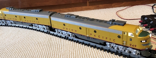
Personally I have never built a brass kit although the E9s are an interest of mine (specifically the UP engines and I have the latest Legacy version of the 949-951 A-A set).

I have always reckoned that I do not have the soldering skills for construction although I have done a minimal amount of resistance soldering. Plus there is the painting prep and actual painting, although from your previous posts you have all the skills, and more, needed for that!

Very much looking forward to seeing how you get on.

My only project of a similar kind is converting a Legacy SuperBass E7 B unit to run with the E9 set:

E9s_A-A

For whatever reason, Lionel has never produced any E8/9 B unit, or at least not one of scale dimensions. MTH has done a scale E8 in their Premier line, which is close enough for my purposes at least in terms of appearances. I have tracked one down and it will be a matter of my usual crude kitbashing to see if the shell will fit on the Lionel E7 chassis. The colors are generally a close match.

Attachments

Images (1)
  • E9s_A-A

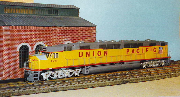
I've built a few LWS locomotives, including this UP DDa40x.  While the kit parts photo shows all the exterior parts, there is no interior floor or underframe.  You will need to make an underframe with supports for the motor(s) and truck mountings. Also the coupler mountings on each end, and get the locomotive to ride at its correct scale height.  On the DD, using brass structural parts, like "I" beams, "C"s and "L"s, I made an underframe to hold two Pittman 9xxxx motors, each driving a truck through Central  Locomotive Works transmissions. A floor was put in only under the cab, which was detailed inside.

The sprung, soft metal trucks were reinforced with brass backing plates and fitted with brass journals for better wear resistance. Because the DD is such a long locomotive, I made articulated coupler mountings for each end to enable the couplers to swing wide and remain close to center on curves. It was able to negotiate a 60" radius curve, but had a good deal of mid-body side overhang in doing so.  A 72" radius was better. It could haul a 60 car freight with metal wheels a scale 65 MPH. The roar from all those wheels was almost deafening!  I built it for a friend and fellow O scaler who has since passed away. His family sold the model and I have no idea where it went.

In this photo, taken when finished in 1980, it is standing on a  section of road bed with steel, hand-laid NY Society of Model Engineers AAR profile rails that were custom rolled in the late 1930's. It was once a part of General Electric's model railroad club O scale layout in Schenectady.  The ballast was made with roofing shingles glued on to pre-cut plywood roadbed.

                     UP6905a

S. Islander

Attachments

Images (1)
  • UP6905a: LWS kit built UP DDa40x completed in 1980.

Very interesting for sure'.  I look forward to seeing the final finished model. What are you going to use for motor power and lighting?

Thanks @Quarter Gauger 48 .  I remember a comment you made I while ago about how much it costs to add little brass details on these trains.  My wife already calls this one the "gold" engine.  I'm hope she is referring to the locomotives metal's color and not how much its going to cost to get it running.   lol

For power/control, I was planning on reusing an older TMCC control board that got pulled out of a working engine during an EER upgrade.  It only has terminals for the front LED headlight.  The cost was right and I will only be sacrificing a backup light and independent cab lighting.

Last edited by T.Albers
@Hancock52 posted:

Personally I have never built a brass kit although the E9s are an interest of mine (specifically the UP engines and I have the latest Legacy version of the 949-951 A-A set).

I have always reckoned that I do not have the soldering skills for construction although I have done a minimal amount of resistance soldering. Plus there is the painting prep and actual painting, although from your previous posts you have all the skills, and more, needed for that!

Very much looking forward to seeing how you get on.

My only project of a similar kind is converting a Legacy SuperBass E7 B unit to run with the E9 set:

E9s_A-A

For whatever reason, Lionel has never produced any E8/9 B unit, or at least not one of scale dimensions. MTH has done a scale E8 in their Premier line, which is close enough for my purposes at least in terms of appearances. I have tracked one down and it will be a matter of my usual crude kitbashing to see if the shell will fit on the Lionel E7 chassis. The colors are generally a close match.

Thanks @Hancock52 I have never build a brass kit before either.  My experience so far has been the ability to solder two electrical wires together.

The new Lionel legacy engines are beautiful and I will be trying to specifically duplicate the Union Pacific E9's.   A few day ago I ordered Volume 8, Issue #4 from the Union Pacific Historical Society that has information about the E9's.  This issues has an article by Robert Darwin that is suppose to cover UP’s new passenger diesels that were delivered in mid 1950's.  I'm hoping it also has lots of detailed photos.   I will let you know if it turns out to be a good issue.

Since my wife has taken a liking to this golden engine I don't plan on painting it.  It's still a long ways away, but I read on the forum that brass can be painted with a clear gloss to keep it from tarnishing.

Keep me updated on your B unit project.  I would like to do make a brass B unit at some point also.

Last edited by T.Albers
@Norton posted:

I was going to ask the same question. Might be easier to find a complete frame with drive. There are a number on eBay now. If you can’t find one thats appropriate PM me for a source.

Pete

Hi Pete, yes that's my plan.  I have a lead on a used E8 frame/chassis with twin DC can motors and committed to purchase it from the seller.

If this build turns out successful I would like to find a matching B unit frame and will definitely reach out to you.

Last edited by T.Albers
@GG1 4877 posted:

I am looking forward to seeing your progress.  I want to learn more about working with brass myself for a future projects.

Thanks @GG1 4877, I have been working on this kit all day and it's going slow.  Not impossible, but really slow.

After a days work I don't have any new progress to show you guys.  This my first time trying to build an O scale kit.  And my first brass anything.  I think I dove straight into the deep-end by choosing a brass locomotive.  🙂

I don't know if I'm going to make all the right decisions while building it but I'm going to learn!

@S. Islander posted:

I've built a few LWS locomotives, including this UP DDa40x.  While the kit parts photo shows all the exterior parts, there is no interior floor or underframe.  You will need to make an underframe with supports for the motor(s) and truck mountings. Also the coupler mountings on each end, and get the locomotive to ride at its correct scale height.  On the DD, using brass structural parts, like "I" beams, "C"s and "L"s, I made an underframe to hold two Pittman 9xxxx motors, each driving a truck through Central  Locomotive Works transmissions. A floor was put in only under the cab, which was detailed inside.

The sprung, soft metal trucks were reinforced with brass backing plates and fitted with brass journals for better wear resistance. Because the DD is such a long locomotive, I made articulated coupler mountings for each end to enable the couplers to swing wide and remain close to center on curves. It was able to negotiate a 60" radius curve, but had a good deal of mid-body side overhang in doing so.  A 72" radius was better. It could haul a 60 car freight with metal wheels a scale 65 MPH. The roar from all those wheels was almost deafening!  I built it for a friend and fellow O scaler who has since passed away. His family sold the model and I have no idea where it went.

In this photo, taken when finished in 1980, it is standing on a  section of road bed with steel, hand-laid NY Society of Model Engineers AAR profile rails that were custom rolled in the late 1930's. It was once a part of General Electric's model railroad club O scale layout in Schenectady.  The ballast was made with roofing shingles glued on to pre-cut plywood roadbed.

                     UP6905a

S. Islander

@S. Islander that DDa40X is fantastic!  I read in OSR issue #37 Locomotive Workshops was going to produce this engine in brass and the #6905 you built looks amazing.  Do unbuilt brass DDa40X kits still come up for sale online or at train swap meets?  I don't know how many of these DDa40X kits Locomotive Workshop could have manufactured for customers being it takes a massive layout to run, especially if your pulling 60+ freight cars.  👍 

Thank you for the helpful building tips.  I have been finding the Locomotive Workshop instructions less then complete.   

Update Feb 14th

I wasn't planning on doing a step-by-step how to article on the proper way to build a brass locomotive because I have never build one before.  The hope is to share my first time experience of trying to build this brass kit so today’s forum members can learn.  In the March 1972 issues of OSR editor Corey Jones said “The object of this magazine is to provide the basis for sharing ideas and methods of model railroading in O Gauge… and O Scale”.

To build the kit correctly was planning on carefully following the detailed steps shown in the original Locomotive Workshop instructions.   1st Problem.  As @mwb mentioned above they don’t give step-by-step instructions!  This kit only included a suggestion sheet.   I needed more than just suggestions.  So, I put away the kit and went back to reading more issues of OSR to learn from model builders during this time period.


I found insight on building a brass locomotive in the February 1978 issue of OSR magazine (issue #54).  On page 14 of this magazine Dr. James F. Eudaly gave photos and covers general techniques on assembling a Locomotive Workshop's U-33c brass locomotive kit.  To assemble the different parts of the kit he used solder, epoxy and CA glue.   Armed with this new knowledge I open the Locomotive Workshop's instruction sheet again (scratch that, suggestion sheet) and started with number 1.

1. Cutouts:

There are a number of cutout to be made in the body shell.  The portholes and side door cuts may be made before soldering on the ends, but all roof cut should be held until the body in structurally complete.

That’s it… nothing more was said.  Well, honestly I didn’t like suggestion number 1.  The brass sides move under any kind of light pressure.  I decided it would be better to wait until after the body is more structurally complete and use 1” thick wood supports inside the shell to reinforce while drilling portholes.  Well, on to the next suggestion.

thumbnail_IMG_9197


2. Nose: Cutout the windshield before soldering the nose to the body of the shell.

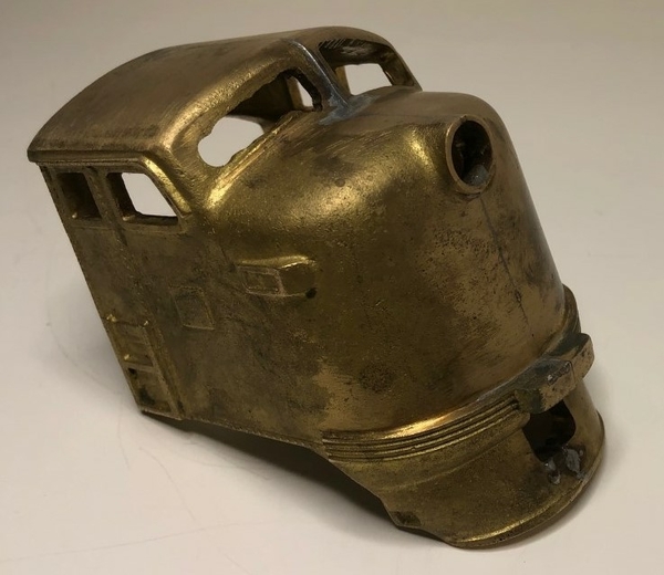
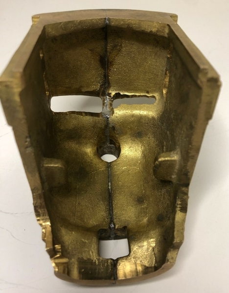
There’s lots of difficult work to complete in that short little sentence of suggestion #2.  As you can see below only the fireman side of the brass nose casting has been cutout from the factory to resemble a windshield opening.   

thumbnail_IMG_9173


And the next part of section 2 it reads: On the E9, remove the number boards.

Ok then… it looks like only the fireman’s side of the nose casting comes from factory in a finished state.  Locomotive Workshop must be giving examples for the person building this kit and expects me to make the other side of the cab match.  At this point it's time to bring out the Dremel with cutting bit.  Also, I need to drive over to Harbor Freight today to buy their 12 pack of fine jeweler's files for the finishing work around the window.


Stay tuned for the next update in this adventure!

Attachments

Images (2)
  • Brass shell porthole
  • Brass nose casting
Last edited by T.Albers
@T.Albers posted:

2. Nose: Cutout the windshield before soldering the nose to the body of the shell.

There’s lots of difficult work to complete in that short little sentence of suggestion #2.

I remember in the "instructions" for my LWS PRR H1, "Assemble the mechanism".  Nothing more that that......so you really had to know how to build the kit w/o the instructions.  Except in my case the mechanism was a physical impossibility,

@Strummer posted:

Fascinating stuff; thanks for doing this!

Mark in Oregon

Thank you for the support @Strummer.  When I purchased this LWS kit I knew removing the extra brass from the window opening would be a turning point in this build.   I decided if I can successfully remove this extra brass materiel without messing up the window line then I will continue building.   If not, this adventure is over and it goes back into its box again.

thumbnail_IMG_9178


  I now have the files from Harbor Freight and will let you know how it turns out!

Attachments

Images (1)
  • Brass nose casting and E7 number board
@Johnbeere posted:

That window shouldn't be too hard to do. I suggest marking a line to give you some reference point as to where you need to stop filing. If you remove too much material, you could add more material by soldering something to it and filing that down.

Yes.  Decent files and patience are key components to success.

Good suggestions on the line / reference points!

This is how you learn to scratchbuild.  A couple of cautions and/or comments:  The nose appears to have been worked on prior to your acquisition.  Not at all sure it left LocoWorks that way - Jan did not generally provide brass castings, preferring something called "Brittania metal."  The window opening looks just a hair too large, although it is of the correct shape.  As above, a layer of brass on top and bottom, and file to shape is the key.

I have carved two such windshields in the last month - a PA and an E7.  I used a Dremel with carbide burr for the rough cuts, but it takes a steady hand and some experience.  Goes really fast.  Do not hesitate to spend money on good files, and remember - files get dull quickly and then become semi-useless.

If the sides are dead-soft (as in bend or deform easily) you are probably doomed.  Brass in the half-hard state works much more easily.  It is not impossible to make your own sides - you use maybe .025 or .032 HH brass, cut to shape, pinned and soldered to roof and ends, and then solder .010 battens, suitably impressed, on to the sides.  This is not easy, but it will teach you a lot about soldering, which is what your goal is.

DSC02944

Here is one I am working on - I did not do the rivet strips, but did straighten them out a bit, and added some vertical detail to the openings in the side.  You can see that the nose is similar to the one in your kit.

Attachments

Images (1)
  • DSC02944

Oh - one more.  On those portholes, you are better off drilling before assembly, but you absolutely need zero rake drill bits and a good drill press.  You need to clamp the sides securely on a wood block and to the drill press table.  "Step-drills" are usually zero rake, and work well on work that is properly clamped.

You need zero rake drills for all holes bigger than #56.  Difficult to buy, but you can dress regular drills with a Dremel cutoff disc and a magnifying glass.  Drilling brass with ordinary twist drills varies from unsuccessful to dangerous. 

@Hancock52 posted:

Wow, that is one rough casting of the cab section. I wish you luck trying to keep this in a brass finish - it obviously wasn’t intended to be left unprimed/painted. Be careful if you use an electric tool to grind excess brass away - from experience with polishing rough brass hardware, the dust is really no good for you!

Lol, yes... the cab section pretty rough.  It won't be winning any beauty contests!

It's a good entry level brass locomotive for a beginner like me.  And I will polish it up the best I can.

Last edited by T.Albers
@Johnbeere posted:

That window shouldn't be too hard to do. I suggest marking a line to give you some reference point as to where you need to stop filing. If you remove too much material, you could add more material by soldering something to it and filing that down.

Thank you for the helpful pointers @Johnbeere .  I didn't know I could add back material if I cut to much away.

This forum is great and has given me more helpful information about building a brass locomotive than all the original LWS instructions! 

@bob2 posted:

This is how you learn to scratchbuild.  A couple of cautions and/or comments:  The nose appears to have been worked on prior to your acquisition.  Not at all sure it left LocoWorks that way - Jan did not generally provide brass castings, preferring something called "Brittania metal."  The window opening looks just a hair too large, although it is of the correct shape.  As above, a layer of brass on top and bottom, and file to shape is the key.

I have carved two such windshields in the last month - a PA and an E7.  I used a Dremel with carbide burr for the rough cuts, but it takes a steady hand and some experience.  Goes really fast.  Do not hesitate to spend money on good files, and remember - files get dull quickly and then become semi-useless.

If the sides are dead-soft (as in bend or deform easily) you are probably doomed.  Brass in the half-hard state works much more easily.  It is not impossible to make your own sides - you use maybe .025 or .032 HH brass, cut to shape, pinned and soldered to roof and ends, and then solder .010 battens, suitably impressed, on to the sides.  This is not easy, but it will teach you a lot about soldering, which is what your goal is.

Here is one I am working on - I did not do the rivet strips, but did straighten them out a bit, and added some vertical detail to the openings in the side.  You can see that the nose is similar to the one in your kit.

Thank you for the detailed advice @bob2 .  I hope my project turns out as good as your E7 photo!   

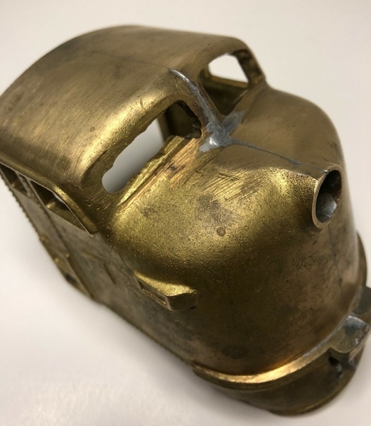
I believe you are correct about somebody working on this brass nose casting before I got it.   The nose casting came with some deep scratches/gashes directly in front of the engineers window.  I don't think LWS would have sent out an expensive kit like this with those deep marks on the nose.     


thumbnail_IMG_9181

Attachments

Images (1)
  • brass nose scratches
Last edited by T.Albers

Update Feb 16th

Now I see why many of these brass kits don’t get built and end up being called doorstops.  This is not an easy model to build like a plastic airplane or battleship where there‘s a full diagram, everything’s labeled and the instructions are clearly written out.  And if you think about it this kit stayed inside its original shipping box for 50 years.  How many times did the original owner look at this unassembled kit and say… nope, not going to happen today.  Or, what was I thinking?

For years the early OSR magazines had advertisements from O scale kit manufactures with the slogan: Take pride in saying, I built it!  I sure hope I can say that at the end of this project.

The current problem I’m up against is the brass material that needs to be removed from the engineer’s window is more than “a little bit of flash” that gets trimmed-off with an X-Acto knife.   This extra brass material is as thick as the nose casting.

thumbnail_IMG_9179


I thought out my situation and decided to create a paper pattern of the good window from the engineer’s side of the cab.  I took this paper pattern and flipped it over.  Then, using reference point lines as suggested by @Johnbeere I traced the outline on the engineer’s side of the cab with a fine tipped ink pen.  With a Dremel and files I carefully removed the extra brass material from inside the engineer’s window all the way out to the marked reference lines.

Next, that single E7 style number board was progressively removed from the engineer’s side of the nose casting.  I started with a medium flat file, then switch to a fine flat file and I finally smoothed everything over with fine grain 800 wet/dry sand paper.

thumbnail_IMG_9220


Success!  Removing the extra brass worked just like you guys said it would.  That means this build will continue.  👍

Stay tuned for the next update…

Attachments

Images (2)
  • inside nose casting
  • extra brass removed from nose casting
Last edited by T.Albers
@Johnbeere posted:

Looks good! You may need to do some more work evening out the two windows, though, since they don't appear to be perfectly lined up. I know that would bug me a lot.

Now that you mention it . . . I also see that now but this is the old problem of not being able to duplicate machine-made accuracy.

The cab area has polished up nicely so far. If this is Britannia Metal I have worked with it before (not on scale models though) and found it more effort than brass. It's generally harder and stronger than brass or different tin alloys. It's generally silver/pewter in appearance so I don't know if this shell is plated or has been mixed in such a way as to produce the brass/gold coloring.

Well, you can get pretty accurate with a file if you take it slow. Just remove metal slowly until they line up just right, I'm sure he can do it. Were I doing it, I might get a straight edge, like a ruler, and use it to visualize how even the two sides are.

I assume it's just brass, brass is a very common metal for these old kits.

It looks like an Adams & Son nose.

When you get ready to solder the sides, remember that this is a two piece nose, and if you get it hot enough it will slip.  Run a bolt through the cab windows and snug it up. Wrap a damp rag around the nose.  Heat only the casting; never the thin sides, when attaching thin stuff to heavy brass.  And always clamp everything.

other option is get the Lionel E8 fuel tank which has the speaker cut out and speaker mount in it. Lionel parts is all A la Carte!

Agreed, but at least in most cases they give you a full a la carte menu - even if many parts are unavailable! I also agree getting the parts you mention, although based on my past experience fitting in speakers is a matter of trial and error.

@bob2 posted:

It looks like an Adams & Son nose.

When you get ready to solder the sides, remember that this is a two piece nose, and if you get it hot enough it will slip.  Run a bolt through the cab windows and snug it up. Wrap a damp rag around the nose.  Heat only the casting; never the thin sides, when attaching thin stuff to heavy brass.  And always clamp everything.

Holy Cow @bob2 I did not know the nose casting could slip apart if it gets too hot.  THANK YOU!  That's is a real important piece of information going forward!

Last edited by T.Albers

Soldering these kits is not difficult with knowledge.  CLW used to offer a service - jig-soldering the cast nose onto the sheet sides, because so many found it daunting.

I find LocoWorks kits daunting, but the actual soldering process is the same.

Get all joints clean and shiny.  Clamp all pieces to be soldered securely - I use the truck mounting brass bars to hold things, with brass 2-56 FH screws part of the assembly.  After soldering the screw heads are filed and sanded flush with the sides.

I use giant C clamps front and back; special threaded spacer blocks to hold sides parallel and hold the roof securely, and use window openings when possible for the screws that go into the spacer blocks.  My roofs are always bronze castings, so plugging small threaded holes is trivial.

And most important of all, when heating never let the flame actually touch sheet metal, unless it is truly momentary.  You can easily anneal or warp sheet metal with a torch.  Once toasty warm, an 80 Watt soldering iron will run a beautiful sheet metal-to-sheet metal seam.  Sheet metal-to-casting seams are always done with torch flame on the casting only.  The casting will heat the sheet metal.

Update Feb 18th

The next sentence (still under suggestion 2) read:  A piece of 1/8” square brass may be used to shim the shell to the nose.

Small problem. 1/8” brass squares are not included with this kit.  Didn’t that original 1970’s magazine advertisement for this locomotive kit say it came “basically complete”?   To move forward with this building adventure I needed to hunt down and purchase K&S Precision metals part #8151, 1/8” x 12” square brass.   In the photo below you can see the empty area in the nose casting were the 1/8” square brass needs to go.

thumbnail_IMG_9195


Once the 1/8” square brass arrived I found it was still .02” short from making a flush fit with the sides of the nose casting.  To make these 1/8” square fit correctly I also needed .01” thick x 1/8” wide strips of flat brass and placed them under the K&S square brass.

thumbnail_IMG_9232


Here’s a look at the 1/8” square brass adjusted outward.  Now this section matches the width of the nose casting and shell after using the two .01” flat brass strips underneath.

thumbnail_IMG_9230


It’s slow going but forward progress is being made.  Stay tuned for the next update.

Attachments

Images (3)
  • missing 1/8" square brass in this section
  • K&S metal strips used
  • fixed the section that was missing 1/8" square brass

Where are you getting .010 brass?  I swear I have a large sheet (four feet!) of it, but cannot find it.  And K&S stopped sticking it in those little expensive packages.

The nose was apparently designed for the "Exacta" cast sides, which dovetail in there nicely.  I don't remember such nice rivet detail on the Exacta models, but it is possible the nose was a later Adams casting for the F3/F7, which did have cast sides with rivet detail.  Some of these are showing up on eBay, as part of Steve Neill's collection.

holding those sides against the shims for soldering will show you the need for rigid clamping of the entire body before applying heat.

@bob2 posted:

Where are you getting .010 brass?  I swear I have a large sheet (four feet!) of it, but cannot find it.  And K&S stopped sticking it in those little expensive packages.

The nose was apparently designed for the "Exacta" cast sides, which dovetail in there nicely.  I don't remember such nice rivet detail on the Exacta models, but it is possible the nose was a later Adams casting for the F3/F7, which did have cast sides with rivet detail.  Some of these are showing up on eBay, as part of Steve Neill's collection.

holding those sides against the shims for soldering will show you the need for rigid clamping of the entire body before applying heat.

I bought those .010 brass strips a few months ago at Pegasus Hobbies in Montclair, CA.   Originally the brass strips where suppose to be for an ACF dome but that project ended up going a different direction.

Pegasus has a shelf in the store with several boxes of miscellaneous old brass tubes, strips, sheets and squares.  It was like a swap meet, everything was loose and nothing was in packages.  Pegasus recently moved to a new location last month and I have not been to their new store yet to see if they still have these boxes of old brass.  I will let you know if they have .010 brass strips next time I go by.     

Update Feb 20th

The next sentence (still under suggestion number 2) said: It will also be easier to attached the nose to the shell if a piece of scrap brass is cut to the shape of the back of the nose casting, soldered to the shell and then screwed to the back of the nose casting.

I have not been looking forward to this point of the build.  The problem is LWS messed up the upper corner bends on the engineer’s side of the shell.  I have never build a brass locomotive kit but I can tell you this square roof bend did not match either the round end cap or the round nose casting.  You will need to work real hard to un-bend that shells square corner… while at the same time holding the shell in place with clamps… while at the same time securing the rear end cap to the shell with clamps… while at the same time making sure all these parts don’t fall off the bench.

thumbnail_IMG_9190


I have read in other forum threads that soldering brass was like an art form, the more your practice the better you will get.  That is a true statement and see lots of forum members who are absolute artists in soldering brass.   I tried it… I’m not one of those guys.   All during this building adventure I have been desperately practicing my solder skills on the brass fuel tank pieces that came with the kit.  Even with practice my brass solder connections looked awful and just too embarrassing to post on this forum.

I’m nervous to admit it but instead of soldering I attempted using CA glue as recommend back in that Feb 1978 OSR issue.  From K&S metals I purchase a 3/16” brass right angle (part #9881) that was 12” long to help with the shells assembly.  This right angle brass was cut into ½” brackets, sanded and tacked on with CA glue to the locomotives rear end piece.  Also, right angle brackets were sanded and placed inside the shells inside front edge where it will meet with the brass nose casting.  Fail.

I quickly found out CA glue does not hold on to large structural brass components.  Apparently, CA glue is only meant to hold non-structural components or very small brass details.  So, I tried again, this time epoxy was used as recommended back in OSR issue #54.  Fail again.  I found out epoxy is too brittle for this type application and rear end cap broke off the shell with a small amount of pressure.

thumbnail_IMG_9233thumbnail_IMG_9234


Okay at this point, this LWS E9 kit was either going back into its original box to live a lonely life as a 4-pound doorstop or I had to learn how to solder brass.  Searching on YouTube I found a 10-minute video called “Soldering for Scale Modelers”.  After watching this instructional how-to video I gave the shell another attempt using my tools.

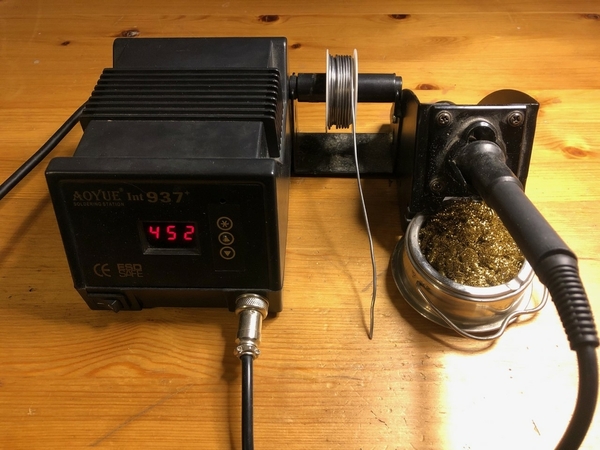
I pulled out a soldering station my son gave me, can of Weller tip tinner, can of Weller rosin flux paste, roll of 60/40 solder and then scrubbed with sand paper and cleaned the glue off the shell’s inside walls.  I followed that video’s instructions but just couldn’t get enough heat to both brass sides at the same time for my solder to flow smoothly. I realized at this point the person in that video was working with much thinner brass sheets and the tip on my solder iron was much too small for this kind of work.  Sure, a couple solder globs were holding in a few places inside the shell but it looked like chewed-up bubble gum.  

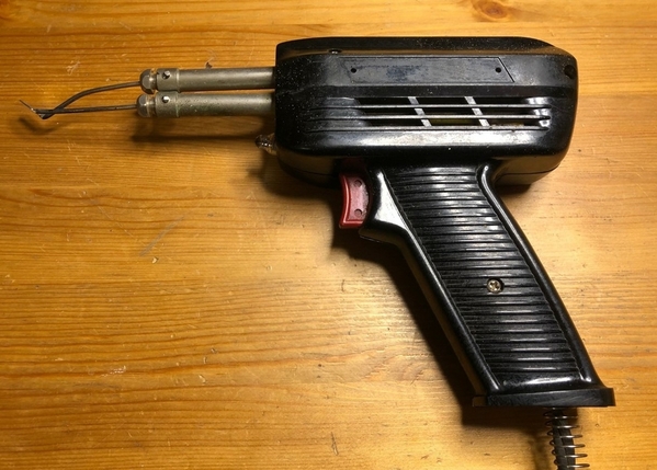
Next, I pulled out my old soldering gun with a flat tip and tried again.  Nope, still not enough uniform heat to the shell’s brass joints.   I just don’t have the right tools for this job.

thumbnail_IMG_9243  thumbnail_IMG_9244


Then I re-read what @bob2 said above in the post about using a flame.  So, I drove down to the hardware store and purchased a micro torch and can of butane.   A quick hit with the micro torch inside the brass shell and the problem was solved!  Thank you @bob2 for the solid advice, you saved this project.

thumbnail_IMG_9245


Guys, I’m not going to get everything right on my first brass kit but I’m trying (and sharing what not to do).  I’ll continue to practice on the fuel tank with my soldering iron.  It's clear now my next purchase needs to be an assortment of larger tips for the soldering iron.


Stay tuned for the next update…

Attachments

Images (6)
  • round end cap square shell
  • glue on end cap
  • epoxy on shell
  • soldering station
  • soldering gun
  • solder joint between end cap and shell
Last edited by T.Albers
@T.Albers posted:
Then I re-read what @bob2 said above in the post about using a flame.  So, I drove to the hardware store and purchased a micro torch and small can of butane.   A quick hit with the micro torch inside the brass shell and that solved the problem!  Thank you @bob2 for the solid advice, you saved this project.

The micro torch is my preferred soldering tool; rare that I use an iron or gun except for electrical bits.  I migrated to the torch years ago as it just seemed "right" in my hands. You use what works for you.  Practice and more practice. And, then setting up and prepping, and getting everything "just so" before soldering is key.

That roof is not salvageable.  The cab casting roof is the correct contour and arch for an E series locomotive (or F, for that matter).  There are several Adams roofs on eBay at the moment - capture one.  Then carefully shear that wrapper (on a big shear; not with tin snips).  Use only the sides.

As Martin says: " the right tool . . ."

You need a new 80 Watt iron for the little stuff, a Micro Torch for precision joints not needing a lot of heat, and a can of MAPP gas hooked to a pencil burner to heat the Adams castings.

Good to see someone else learning the same stuff I am at the moment. I just started learning how to solder with a torch for my GMC Pacific once I realized that a soldering iron was not going to cut it to heat the brass. What I've learned is that lots of flux and lots of heat is very important, if you don't have enough heat the solder won't flow correctly.

Something I'm realizing is that certain tasks seems daunting until you know how to actually do them properly, then everything begins to be much easier. Whenever I get frustrated with the way I'm trying to do something, it turns out I just don't know the right way. The forum has helped greatly with me learning the proper way to do things.

@mwb posted:

The micro torch is my preferred soldering tool; rare that I use an iron or gun except for electrical bits.  I migrated to the torch years ago as it just seemed "right" in my hands. You use what works for you.  Practice and more practice. And, then setting up and prepping, and getting everything "just so" before soldering is key.

Thank you Martin for the advice.  I didn't know about using a flame, I thought I had to use a soldering iron.  I cannot believe how much easier it was to solder brass with a micro torch.  I was very careful to be quick with the flame and not to overheat or warp any of the brass sides.

For me, this torch changes the whole game on building a brass kit.  Now I have confidence I can finish this project.

I don't know if you need to be so careful about heating it for too long, just avoid getting the metal red hot and it should be fine. Your solder joint a few posts above probably could be improved with some more heat, actually.

This is a little off-topic, but I recently figured out how to form some handrail stanchions by getting a 1/16 brass rod red hot, hammering the end flat, and then creating a curve at the end. What I found was I could get the metal red hot safely as long as I removed the flame as soon as it was red. You might try heating a piece of brass stock to see how it behaves when it gets that hot to give you an idea of how much heat you can safely apply. Of course, the smaller the piece, the quicker it will be to heat it up.

@Johnbeere posted:

I don't know if you need to be so careful about heating it for too long, just avoid getting the metal red hot and it should be fine. Your solder joint a few posts above probably could be improved with some more heat, actually.

This is a little off-topic, but I recently figured out how to form some handrail stanchions by getting a 1/16 brass rod red hot, hammering the end flat, and then creating a curve at the end. What I found was I could get the metal red hot safely as long as I removed the flame as soon as it was red. You might try heating a piece of brass stock to see how it behaves when it gets that hot to give you an idea of how much heat you can safely apply. Of course, the smaller the piece, the quicker it will be to heat it up.

Thanks @johnbeere, my plan is to leave this engine in a brass finish.   I read that after a good polishing the shell can be sealed from future oxidation with a clear gloss coat.

That's why  I'm being so careful with heat while using this micro torch.  I'm afraid to overheat the brass because it might leave a permanent burn mark that everyone will see.   I checked out those roof castings on eBay @bob2 mentioned above.  I don't have the skill set to separate the existing LWS roof and add a new Adams cast roof without damaging the panels.   This is my first build and I know it won't be perfect but I'm going to give it a good effort.     

I just finished using the micro touch for attaching the brass nose casting to side panels.  Everything is holding together.   I will take some photos later and post an update. 

@T.Albers posted:

I just finished using the micro touch for attaching the brass nose casting to side panels.  Everything is holding together.   I will take some photos later and post an update.

I’ll be interested to see that. I thought that this sort of assembly was where resistance soldering excelled but I admit I’ve only experimented with it and not on attaching brass panels.

I have a cast PA that is now polished.  I like it!  It will stay bare brass, and maybe get a polished PB to go with it.

If you got the nose successfully attached, you are well on your way to expert status.  The rest will be easy.

While I disagree about heat not hurting until the sheet turns red ( brass will partially anneal before turning red) once you get good with the torch, you can attach handrails.

Clean the handrail and body + hole area.  Flatten a teeny chip of solder and nestle it up against the inserted handrail.  Paste flux will hold it.

Then - this is important - heat only the sheet metal.  Don’t let the flame hit the handrail or it will instantly turn red and destroy itself.  The solder will leap into a small and perfect funnel shape, and pull your torch immediately out of there.

Update Feb 22nd

The rear end piece is holding great after being soldered from the inside with a micro torch.   Also, I didn't damaged the outside of the shell using a flame.   I read the extra flux can be cleaned off with a little dish soap, baking soda and warm water.  The brass shell will be polished with Brasso once I have it all together because it still shows 50-years of dirt and tarnish.  I found an 8 oz. bottle of this stuff on sale for $2.98 plus free shipping.

thumbnail_IMG_9246 Feb 21st


The next big item was soldering the nose casting to the shell.  I clamped outsides of the nose together and used a wet rag as a heat sink as recommended previously.  The micro torch heated up the nose casting and it accepted solder just fine. 

@Hancock52 I did not want to chance this front solder connection ever coming apart (plus my soldering joint looked ugly).  So for extra insurance on top of that solder joint I also applied JB weld inside where the brass nose meets the shell.  Now, I have to wait 24 hours for the JB weld to fully dry.

thumbnail_IMG_9248 Feb 21st


I wouldn’t have to wait 24 hours for the JB weld to dry if I would have trusted my newly learned skill of soldering with a micro torch.  While pondering my lack of metal crafting skills I found another LWS advertisement in an old OSR.

In the October 1977 issue of OSR magazine (issue #46) Locomotive Workshop reissued this E9 kit for $104.95.  The cab’s nose casting on this newer 1977 kit was done in soft white metal.  The description of this reissued LWS kit read:  Above include double etched brass super structure cast Brittania metal nose (solderable), brass details, and sprung truck kits.  Wheelsets & power available separately.  In 1977 a $104.95 kit would calculate to about $451 in today’s dollars without the B-Unit.  That 1977 advertisement listed the B-Unit separately for an additional cost of $89.95.


Stay tuned, after the JB weld dries I will post another update.

Attachments

Images (2)
  • End cap on shell
  • nose casting on shell

The look of your solder joints may be from a hesitation to use enough heat. While you should be careful, you shouldn't be too afraid of using too much heat. That nose casting will be soaking up most of the heat during soldering due to its size, so you probably can put quite a lot onto it without causing any damage. Otherwise, nice to see some progress... You're probably going to be finished before I get done with my Pacific.

Update Feb 23rd

@bob2 here’s the shell to nose front connection you requested.   It’s not great.  The 1/8” square on the engineer’s side slipped down at some point during the clamping/soldering process.  The empty space at the top of the 1/8” square does not bother me but I will file the bottom of the 1/8” square smooth so it matches the bottom line of the nose castings.

thumbnail_IMG_9249 a cab transition


@Hancock52 the Union Pacific Historical Society Volume 8, Issue #4 arrived.  I thought it was going to cover the UP’s E9 passenger diesels that were delivered in mid 1950's.  Instead it was an article about the rebuilding of the 949 and 951 in spring 1993.  It was 6 pages long and had lots of photos.


@Johnbeere you had mentioned I might finish this E9 project before your Pacific gets done.  You may be correct because I made lots of easy progress on the shell since my last update.   With the JB weld dried, I could finally make those four porthole opening on each side of the shell.  Since I don’t have raked drill bits I started with a small standard drill to make a hole in the center and then enlarge the opening to 3/8” using a Dremel tool.  During this process I placed 1” wood supports inside the shell (cut to the shape of the shell) to prevent any stress on my precious solder joints.

thumbnail_IMG_9253 Feb 23rd


Looking at the rest of the instruction sheet I believe the hard work is behind me as I arrived at the 3rd and 4th suggestions on the Locomotive Workshop's sheet of paper.   3. Dynamic brakes (E9 only) – mounts on central hatch and may be deleted in most cases. I read in the old OSR magazines that Locomotive Workshop sometimes used Kemtron brass castings in their kits.  I believe this information is true because this kit came with some very nice 48” and 36” lost wax fan grill castings.

thumbnail_IMG_9249 Feb 23rd


Next, a single 1” opening was made in the roofs center section for the 48” dynamic brake fan grill.  Using the micro torch the 48” grill was then soldered in place and 0000 steel wool was lightly used to clean oxidation from the outside of the shell.

thumbnail_IMG_9256 Feb 23rd


4th suggestion on the Locomotive Workshop's sheet of paper.  4. Winterizing Hatch - Fit a screen in the depressed portion of each pressing.   Problem.  Locomotive Workshop did not provide enough screen material with this kit to fill the depressed portions of both the winterizing hatches.  It’s kind of funny LWS provided two end caps for this E9 “A” locomotive but only included one screen.

thumbnail_IMG_9237 Feb 23rd


I saw this part was missing early in the build so I preordered a new brass screen (part# 48117) from Precision Scale Co.  New 4” x 6”, 60 mesh brass screens were cut with tin snips to fit the winterization hatches. The next sentence under #4 read: The bottom of the hatch can be formed to fit the roof, and then soldered to it.  Screen portions of the hatches fit the center portion of the car body.

The bottom of the winterizing hatches were sanded to match the roof’s curvature and then soldered in place.  0000 steel wool was used again to clean the oxidation marks from the outside of the shell.  Two brass screens were cut and then secured into the depressed portion of each winterizing hatch.

thumbnail_IMG_9258 Feb 23rd


The build is moving along much smoother now.  I have made it past the hard part!  Stay tuned for the next update…

Attachments

Images (6)
  • cab transition
  • Window portholes
  • Kemtron grills
  • 48" dynamic brake grill
  • winterizing hatches
  • roof view with fan and hatches
Last edited by T.Albers

Update Feb 25th

As I look back over things I have learned during this build three items come to the top of my list.

  1. Take time to correctly set & clamp all brass items before soldering
  2. The micro torch is my favorite tool for building a brass kit
  3. Using chips of solder is brilliant. Before this information I was using solder on-a-roll for every single little joint (which left too much solder everywhere and made for some ugly solder joints)

I hope in posting these photos about building this LWS kit other OGR forum members can learn from my trials.  Experienced builders will have better approaches and techniques for assembling these old kits then I do.  What’s important is we are sharing this information so others can learn.  For 54 issues OSR magazine’s front cover showed the phrase “Knowledge is of no value unless it is shared with others”.


Next on my to-do list is I needed to complete the 5th suggestion on the Locomotive Workshops sheet of paper.  5. Fans – mount each fan in a circular hole cut into the depressed area over the engine hatches. A wood support was placed inside the brass shell to prevent it from flexing.  Four ¾” openings were made in the roof to accommodate the 36” fan grills.  I started the openings with a small drill bit and then enlarged them to the correct size with a Dremel tool.  The four 36” fan grills were then secured in place.  @bob2 here’s an overhead photo showing the nose connection to the shell.

thumbnail_IMG_9263 Feb 25th


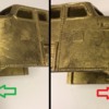
Now seemed like a good point in this project to tackle the front foot step that was only half-molded into the pilot on the engineer’s side of the cab.  You can see from my early project photos the front foot step on the fireman’s side (green arrow) was in the finished state but the engineers foot step (red arrow) was not finished.

thumbnail_IMG_9252a Feb 25th


A Dremel tool with a small cutting bit was used to remove most the thick brass from the center of the engineers foot step.  Then, I carefully squared the step’s inside edges with a small flat file (aka jewelers file).  Here’s the after photo.   @Hancock52 you can see from the older photos above vs. the newer photo below I have been polishing up that rough nose casting.

thumbnail_IMG_9252 arrow Feb 25th


Step 6, is for mounting exhaust stacks if you are building an E7 locomotive. Since I’m building an E9, skip.

Step 7, is for using the 2-rail side truck castings LWS provided.  Since I’m going 3-rail, skip.

Step 8, is for mounting the fuel tank components separately.  Since I’m going to use a 3-rail donor chassis with fuel tank, skip.

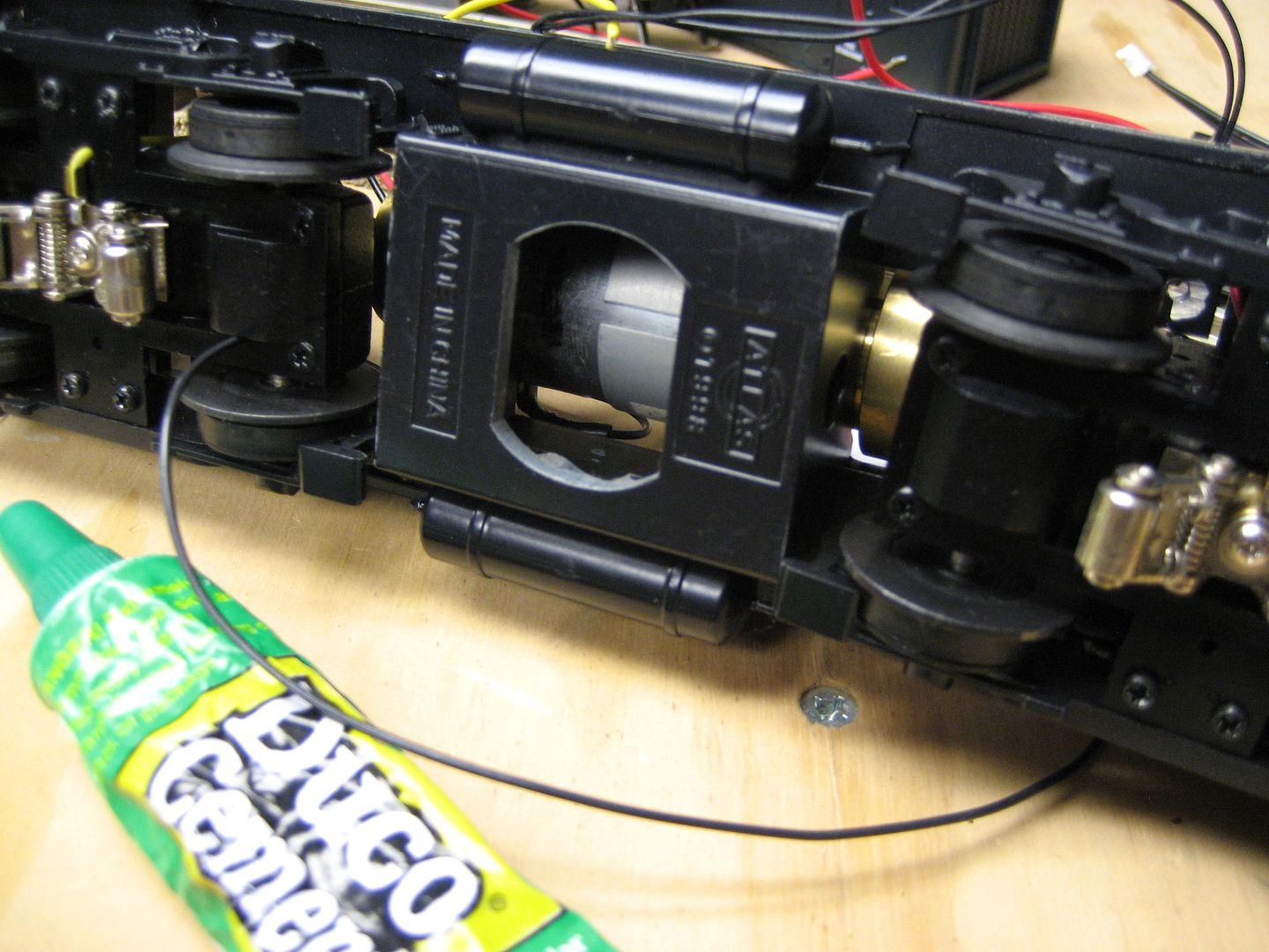
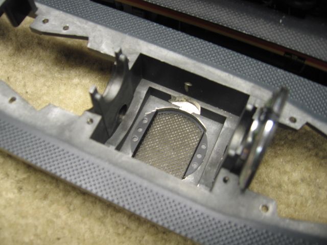
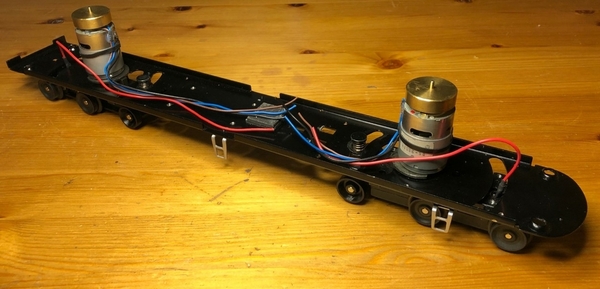
Step 9, is for building a separate frame for mounting a motor and gears.  Since I picked up a 3-rail donor chassis with motors and gears, skip.

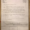
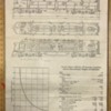
That was the end of the Locomotive Workshop suggestion sheet.  All three sheets that came with this kit are attached below.  The first page of suggestions was as described in this thread.  It covered both E7 and E9 locomotives and seems to have been an afterthought from Jan at Locomotive Workshop in hopes of providing more details with some helpful hand drawings for the kit builder.  It was stapled on top of the second page that had almost identical information but with less details and only covered building an E9.  The third page was plan views and general specifications for the EMD E9A diesel-electric locomotive.


A builder could stop right here and put some wheels underneath this shell and have a pretty brass locomotive sitting on a shelf.  Not me.  Since the kit builder is apparently on his own now for what happens next, I feel this brass locomotive needs more.  Hint:  I have been simultaneously building a cab interior for this E9 so my visitors won’t see inside the empty shell from the front windshield openings.

Stay tuned for the next update!

Attachments

Images (6)
  • Top roof view
  • Rough cab castings
  • new step in pilot
  • LWS suggestion sheet 1
  • LWS suggestion sheet 2
  • LWS suggestion sheet 3
Last edited by T.Albers

Update Feb 27th

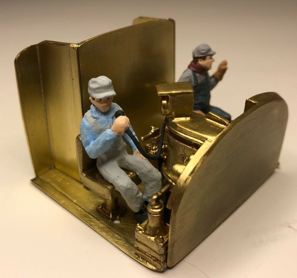
Using drawings from my past E8 interior builds (attached) I created a new floor and walls out of sheets of brass.  I discovered flat brass sheets can be cut, sanded and glued together just like my other cab interiors that were built out of basswood.   The brass floor and walls needed to be slightly smaller than my previous E8 interior builds to allow them to fit inside this thick nose casting.   Note: wear gloves when trimming flat brass sheets on a sander, they get real hot in your hands!

Scale City Design part# 48-041 interior cab details were modified and painted to fit this application.thumbnail_IMG_9305 Feb 27th


The engineer (Scale City Design part# 48-624) was painted and modified to be holding a 2-way radio mic in his right hand.  

thumbnail_IMG_9329 Feb 27th


The fireman’s seat needed to be moved over from my original location so I could get this great looking figure (Arttista part# 1406) to fit inside the E9’s nose casting.

thumbnail_IMG_9324 Feb 27th


I’m still reading those old OSR magazines while building this kit.  In the 1982 issue of OSR magazine (issue #75) pages 21 ~ 22 you can read Jan Lorenzen’s thoughts on O scale business.   Jan gave a second OSR magazine interview for the manufactures junction in a 1986 issue (issue #89).  As Locomotive Workshop expanded he also bought the original molds/parts for Athearn, Lobaugh, Custom Brass Imports and Reynolds.

While researching inside these classic issues I found out he started Locomotive Workshop in 1963 and was involved in O scale brass manufacturing for 40 years.  In 1987 Jan writes a letter to OSR (issue #96 page 59) describing how customers are getting older in our hobby and sales are declining for O scale kit manufactures.


Next, I’m adding more exterior details.   Stay tuned for the next update…

Attachments

Images (4)
  • E-8 cab floor and walls drawing
  • Brass E8/E9 cab
  • Engineer side of cab
  • Fireman side of cab
Last edited by T.Albers
@Hancock52 posted:

Nice touch! I assume that you will leave the cab interior and details polished brass.

Yes, I'm leaving the interior in polished brass for a classic look.  Also, I'm installing a small 2mm warm white light on the roof of the cab to help with a soft warm glow.  I almost did not include the engineer and fireman since I have not seen crew figures in other polished brass locomotives.  But this engine is being made to run on my layout and not sit on a shelf so I decided to include them.   It would have looked odd having two empty seats in the cab as the locomotive roars by blasting its horn and whistle.

thumbnail_IMG_9304


The Scale City Design engineer was in bad shape when I got him.  I asked them for a replacement because flash covered his face.  Scale City did not respond back so I did the best I could with jewelers files to create eyes, nose and a face with the engineer figure I had.

thumbnail_IMG_9291


This build is going much smoother now. I have all the parts and should be finishing soon.

Attachments

Images (2)
  • brass cab interior
  • Scale City 48-624
Last edited by T.Albers

Update March 1st  

Installing exterior details meant I had to drill a bunch of holes into the brass shell and nose casting.  In my opinion, I only got one chance at drilling holes into brass and if I messed up… that hole’s there forever.  Take your time during this step and buy a small drill press if possible.  Only use brand-new sharp drill bits and double and triple check you measurements.  Also, I used masking tape as reference line to help mark the locations as accurate as possible before drilling.

Here’s how I made the two 3mm openings for the classification lights.  First, place masking tape on the brass nose casting and mark your center location.  Then put an arrow on the tape where the classification light should be located on the engineer’s side of the cab.  Next, measure this lights exact location from the center line and copy it to the fireman’s side of the cab.  These lights also need to be located on the same horizontal plane (reference line).  So, make sure the tape is in a straight line to the rear of the nose casting.  Then measure the tapes exact height off the engineer’s rear side of the nose casting and duplicated it on the other side.  These lights were an extra challenge to drill because they were located on a curved surface.  Only use new sharp drill bits because you don’t want a dull bit dancing across your smooth brass surface.  You can now drill your 3mm holes in the brass nose casting for your classification lights.

thumbnail_IMG_9283 March 1st


The lower railings on the pilot was easier to mark because they were already on a fixed horizontal plane.  First mark the cabs center location on the masking tape and then place marks on the tape where you want to drill holes.  Then measure these marks and duplicate these exact locations on other side of the nose casting.   Now you can drill holes for the railings that will be installed in the center grove of the ribbed/art deco pilot.

thumbnail_IMG_9284 March 1st


Inside my original Locomotive Workshop box they also included: 2x brass horns, 6x brass steps, a brass intake cap for the steam generator, enough brass sheets to assemble a fuel tank (now poorly soldered together from my early practice attempts) and 2x brass air intake screens.  Problem.  The 2x brass air intake screens are way to long for an E9A unit.  Locomotive Workshop supplied 16 ½” long side screens from their B unit kit when this A unit should have only been shipped with 13 ½” screens.   In the photo below it shows these parts mentioned plus a few extras.  I’m not sure why they included a second end cap on this “A” unit or that tall brass sheet.

thumbnail_IMG_9267 March 1st


I would recommend drilling all your holes into the shell and nose casting before permanently attaching any small brass details.  The reason is these tiny brass details are fragile and will break off if installed too early (I learned this fun fact the hard way).   Here’s another fun fact:  In the June 1988 OSR magazine issue #99 they wrote the first O-scale diesel locomotive kit with photoengraved brass sides was advertised for sale in a model railroad magazine in May of 1948.

My next move is to finish the chassis and wiring.  Stay tuned for the next update.

Attachments

Images (3)
  • Classification lights
  • lower railing holes
  • Brass details from LWS
Last edited by T.Albers

You are way past this suggestion - I include it for others.  A good spring-loaded center punch and a magnifying lamp can make aligning holes really easy.  Just remember to back up the sheet with steel for the center punch, and with wood for drilling.  No need for backup with castings or heavy sheet.

A hole in the wrong place can be easily filled, even on a polished model.  Just partially tap the hole and run a brass screw in the hole.  Solder helps make it permanent, and you can actually drill into it.  I have fixed many truck sideframes this way, where the axle hole was a half-diameter off.

You really can't see the polish in this shot, but I assure you, there are four plugged holes near the belt line, and you cannot see them.  Even in person.

image

Attachments

Images (1)
  • image
@bob2 posted:

You are way past this suggestion - I include it for others.  A good spring-loaded center punch and a magnifying lamp can make aligning holes really easy.  Just remember to back up the sheet with steel for the center punch, and with wood for drilling.  No need for backup with castings or heavy sheet.

A hole in the wrong place can be easily filled, even on a polished model.  Just partially tap the hole and run a brass screw in the hole.  Solder helps make it permanent, and you can actually drill into it.  I have fixed many truck sideframes this way, where the axle hole was a half-diameter off.

You really can't see the polish in this shot, but I assure you, there are four plugged holes near the belt line, and you cannot see them.  Even in person.

Thank you @bob2 for all your great advice through this build.  Is your polished brass Alco a Central Locomotive Works or Adams & Sons? 

Update, March 3rd

Years ago I remember going into the Train Shack in San Dimas, CA and seeing rows and rows of beautiful brass O scale locomotives displayed on a wall behind glass.  When I inquired about the 3-rail brass trains the store employee chuckled and said “Sure there pretty to look at but small parts break-off when you handle them and they don’t pull as good as modern Lionel or MTH engines”.  The employee smiled as he called that wall of early 3-rail brass Weaver/Williams engines his shelf queens.  I left the store that day and thought, I didn’t want a brass locomotive if it couldn’t pull as good as my other engines.


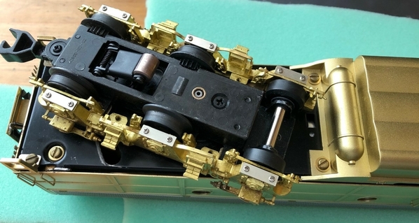
I grew up in the plastic ready-to-run (RTR) era I never knew people built locomotives with custom drivetrains until I became an OGR digital subscriber and read those early magazine issues.  My hats off to all you guys back then.  You picked a transmission based open gears or sealed gears.  Then selected if you wanted the drive train to be flexible shaft, solid shaft or chain drive.  For steam engines you could even pick the exact size of the drivers.  Also, you could choose a motor by the number of windings, if it was open enclosure or enclosed Pitman.  Reading about all those choices gave me confidence going forward.


After many years of doubting a brass locomotives capability this was my chance to make it right.  So far I have only built an empty shell.  Now I needed a 3-rail chassis with motors that would allow it to pull as strong as other modern locomotives.  I ended up buying a used K-Line, twin can DC motored E8 “A” dummy unit without electronics.  The silver K-Line steps in the photo below will be removed and the brass Kemtron steps that came with the Locomotive Workshop kit will be installed.

thumbnail_IMG_9371 March 3rd


Next, I had to install the 6 wheel E9 side frames.  Here's a photo of the 50 year old Locomotive Workshop soft metal side frame castings that came with the original kit.  These just don’t have the fine details I want on this build.

Side frames Locomotive Workshops


I thought about reusing the K-Line side frames that came with the donor chassis.  The K-Line’s side frames have crisper details than the Locomotive Workshop side frames above.

Side frame K-Line


Like all those early OSR magazines said, I wanted to take pride in saying “I built it.   So, I ended up buying part# 965 from American Scale Models.  These come in pieces and have to be assembled.  American Scale Models included very detailed brass lost wax side frames, coil springs, EMD E8/E9 Hyatt journal bearings and other small parts I don’t know the names of.

Side frame and parts American Scale Models


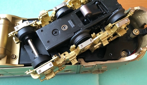
After making small mounting brackets for attaching the brass side frames to the K-Line trucks I did a test fit with the shell.  The rear assembly fit perfect.  The only issue was the front truck needed to be trimmed back (at the arrow) to swing freely under the LWS fixed pilot.   My plan was to use a dummy front coupler on the shells fixed front pilot anyways because my layout has 042 curves.  Also, to help the brass side frames fit a little closer to the K-Line trucks I filed back a small brake shoe (on the inside) near the blind wheel.

Side frame and truck with arrow


I have only been semi-successful in upgrading my other locomotives to ERR.  It wasn’t ERR’s fault.  Their electronics came with full instructions and wiring diagrams.  But I still ended up melting some component on a circuit board.  That was an expensive mistake and the cooked circuit board is sitting around here somewhere.  Maybe I’ll post a photo of it one day when the smell of melted plastic (and money going down a drain) is not so fresh in my mind.  It will be like that T.V. show CSI.  You guy look at the dead ERR board and try to guess how it happened.


Therefore, an older TMCC board with diesel sounds (from another project) was installed so this chassis can run on my layout.   I read the TMCC antenna cannot be installed inside a metal shell, so it will be ran outside and connected to the rear striker plate.  This brass striker plate is isolated from the shell by a soft flexible vestibule so it will be electrically insulated from ground.    In the next photo you can see the front of the steel chassis where it was trimmed back to fit inside the thick brass nose casting.  Also, the fuel tank’s original color from the donor K-Line E8 engine was incorrect for this project so it was painted with Tru-Color brass paint (part# TCP-288) to help it blend in better.  Otherwise the American Scale Models side-frames did not need any modifications to fit next to the fuel tank or under the Locomotive Workshop’s E9 shell.

Side frames on chassis March 3rd


Stay tuned for the final update.

Attachments

Images (6)
  • K-Line E8/E9 chassis
  • Side frames Locomotive Workshops
  • Side frame K-Line
  • Side frame and parts American Scale Models
  • Side frame and truck with arrow
  • Side frames on chassis March 3rd
Last edited by T.Albers

Well, what can I say besides that is a VAST difference and improvement. I did not know about American Scale Models before now - will have a look at their products, which seem first rate - by a long shot.

But, noooo, I am not thinking of going over my last diesel engine project to improve it.

Advice - throw out the failed ERR part, as realistically you will never have a use for its components. ERR boards are VERY sensitive to static and other hazards of DIY efforts. We're lucky that they are available at all through Scott Mann. I have blown more than a couple of these boards, mainly through being impatient. It's best not to let them haunt you.

I look forward to seeing the finished engine. This has been a truly inspiring project, but what I want to see is how you have polished the cab/nose of it!

@bob2 posted:

Yes!  Spectacular power section.  Did not know Bill was importing Diesel trucks.

K-Line was the best choice - I have converted four Train Masters, and really like the all-axle drive.

You are about one click away from becoming a 2-railer.  Be careful.

Certainly is treading closely,   Some really excellent work here with this kit!

Update March 5th, finishing the LWS kit.

Having gone this far trying to build my first brass locomotive kit I didn’t want to fail now.  Those early OSR magazines kept encouraging builders of every skill level to “do the best you can”.  Now I was at the point where I had to select how many exterior details to install on this model.  All along this adventure I have been studying old photos of Union Pacific E8 and E9 locomotives and was ordering small brass details online.   I began with digging through the part numbers shown on Precision Scale’s website.

Precision Scale had windshield wipers part# 5654, door handles part# 5639.  Grab irons part# 5623 were installed after 1959 to meet the ICC-mandated access steps and handholds on the engineers side of the nose casting.   Precision Scale MU hose connector’s part# 5650 are found on several Union Pacific E8A/E9A locomotives like 942, 949 and 951.  The brass rods that were used to make the ladder rest grab irons and hand railing were K&S precision metals part# 4873.  Note: during assembly a piece of 1/32th inch basswood was used underneath all hand railing to help maintain an exact distance between railing and the locomotives surface.

1


Precision Scale also offered 48” fan blades part# 5653, 36” fan blades part# 5682 and brass lift rings part# 48279 (you will needed two packs of these for an E9).  I couldn’t locate E9 roof mounted cooling pipes in brass so I ended up ordering part# 48-051 from Scale City Design and modifying them to fit this application. To get the look of heavy duty dual-wall exhaust stacks on the roof I used 2 different size round brass tubes from K&S precision metals and mounted one pipe inside the other.  The outer pipe was 9/32” part# 8132 and the inner pipe ¼” part# 8131.  The small 3/32” pipe next to the exhaust stack is K&S part# 8126.

2


Then, from the American Scale Models website I ordered left and right side mirrors part# 3066 and the duel diesel headlight insert part# 911.7.  The 13 ½” long stainless steel vertical slot Farr style air intake grills and front number board housings came from the K-Line donor shell.   The window sun shades and oval builder’s plates were created from strips of 2mm x 1 mm flat brass.  In my opinion the perfect way to create that definitive look of a classic polished brass locomotive was to not install windows in the cab.

3


Originally, I purchased 4 EMD rotary knob style sand box covers.   Then while researching online I discovered EMD switched to a newer type after 1954 because the previous rotary style dropped down against the sides of the E8 locomotives and caused damage.  Luckily, American Scale Models offers these newer E9 improved journal type sand box covers part# 923.4.  To hide all the wires, electronics, smoke unit and motors inside the shell six clear windows were cut from a sheet of .010” thick Styrene.  These windows were then painted glossy black only on the Styrene’s backside.  Then, they were attached inside the shell over the porthole openings with the clear side facing out.  The clear window thickness gives my visitors the impression of depth, like they are looking through a glass window and into a darkened engine room.

4


Also, from American Scale Models was this brass striker plate (now discreetly being used as my external TMCC antenna) part# 995-8 and back-up light housing part # 9287.09.  The brass light housing was drilled out and a 2mm warm white tower LED was placed inside.  The 2mm LED is wired to the TMCC board and it only illuminates while the locomotive is in reverse.  The flexible diaphragm is from Scale City Design part# 48-225.

5


The brass rear ladder part# 816-3 was from American Scale Models.  Bow-tie vents over the battery compartments and steam generator exhaust stack came from the K-Line donor shell.  The brass shell and nose was lightly gone over one last time with 0000 steel wool to remove any leftover oxidation.  Then I applied two glossy coats of Tamiya clear spray paint part# TS-13 to seal-in the shiny brass finish from oxidation.

thumbnail_IMG_9570


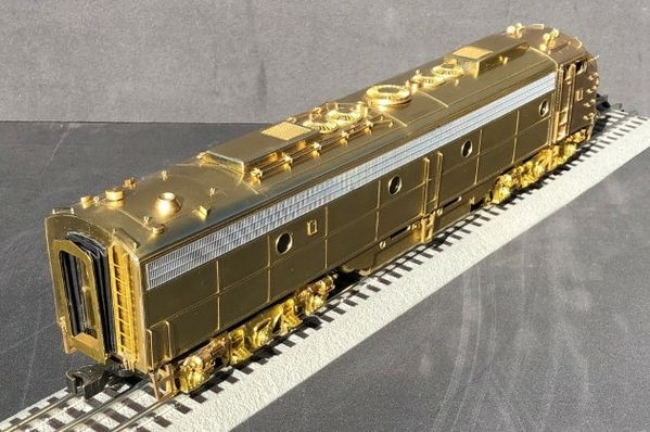
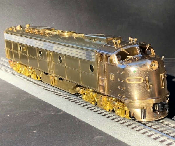
I wanted to say thank you to all the OGR forum members for the great advice during this building adventure.  In an effort to help other forum members who find this thread in the future I have listed all the part numbers used to complete this Locomotive Workshops kit.  Not having a complete parts list of exterior details was like rummaging thru unmarked cardboard parts boxes at a train meet.  Some websites carried a few parts… then I had to search other websites for other parts.  It felt like I was on an online treasure hunt.  But hey, it looks like I got a Golden E9 locomotive at the end of this treasure hunt!  Also, one last fun fact:  I drilled 128 different holes/openings into the shell & nose casting for all those little brass details.   

In closing, I did the best I could building my first brass locomotive kit.   When visitors ask questions about this polished E9 running around the layout, I can proudly say “I built it”.   


Thank you for following this thread.

Attachments

Images (6)
  • LWS nose
  • LWS top
  • LWS front
  • LWS side
  • LWS rear
  • LWS rear top
Last edited by T.Albers

That is a complete transformation from the original kit parts shown at the top of this thread. Well done indeed, because you now have a true jewel of a model loco.

However, I fear that you have come close to going over to the "dark side" of 2 rail scale and are being enticed to cross the fatal line. I'll know you're a goner when you install DCC in something!

Since you are modeling a Union Pacific E8/E9, and VERY NICELY at that, the one "add-on" part, characteristic to all UP E8/E9 units, are snow shields on top of each cooling system winterization hatch. The Overland Models E8/E9 units were really nice, and one could purchase those snow shields as spare parts. I have no idea where one could get those today, and the snow shields on the recent Lionel models don't appear to be var correct, to me.

The 3rd Rail E9's have the snow shields and they are brass castings.  The Amtrak model of which I have 3 of, came with them as add-on parts if one wanted to model the UP variant.  If you are interested, you can email me at my profile email address and I can send you pictures.  I only use the snow shields on one of mine at this point.

Your model is outstanding.  Thanks for sharing the progress!

_IMG0425

Attachments

Images (1)
  • _IMG0425
Last edited by GG1 4877
@bob2 posted:

Spectacular!  Very nice work.

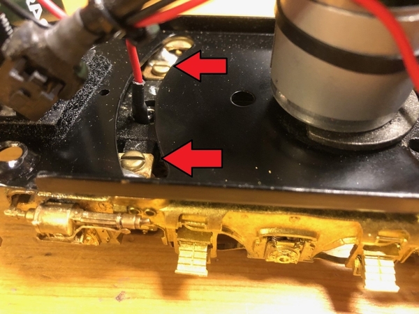
Thank you @bob2.  To help complete the finished look of a classic brass locomotive the modern K-Line #4-40 black Philips screws were changed out on the chassis, fuel tank and side steps.  Brass #4-40 x ¼” slotted pan head screws were ordered and reinstalled at all these locations instead.

thumbnail_IMG_9628


Also changed out were the black Phillips head screws used on the side frames.  Now those locations have brass pan heads.

thumbnail_IMG_9527


A #4-40 x ¾” long round head brass screw was used to hold the front coupler to the K-Line chassis. Matching brass washers and a spacer were installed in locations as needed.

thumbnail_IMG_9629


My visitors may never see these little brass details underneath the locomotive... but I know they are there!  🙂

Attachments

Images (3)
  • thumbnail_IMG_9628
  • thumbnail_IMG_9527
  • thumbnail_IMG_9629
Last edited by T.Albers
@Hancock52 posted:

That is a complete transformation from the original kit parts shown at the top of this thread. Well done indeed, because you now have a true jewel of a model loco.

However, I fear that you have come close to going over to the "dark side" of 2 rail scale and are being enticed to cross the fatal line. I'll know you're a goner when you install DCC in something!

Thanks @Hancock52.  Yes, the before and after photos of the nose casting show a drastic transformation.  Since I was aiming for a polished brass finish I knew in the beginning I would not be able to completely hide all the tiny air bubble depressions in this LWS lost wax nose casting.  But I still tried my best to minimize them.  First, I sanded down the surface help make them smaller, then used steel wool to polish over the surface.  Next, Brasso was used on a toothbrush to remove the dark oxidation hiding inside the tiny depressions.  Another toothbrush was used after that with 91% alcohol to remove the leftover Brasso from inside the depressions before painting.  I was very pleased when the two coats of clear Tamiya gloss helped smooth the brass nose surface even further.

As @bob2 suggested earlier in this thread builders can successfully use a product like Bondo to fill the depressions in the brass casting.  These depressions can be covered with a filler and the surface will be completely smooth to a viewer after it’s primed and painted to match a roads specific color.

thumbnail_IMG_9178


A big concern of mine at the beginning of this build with this rough nose casting was removing the scratches that were directly in front of the engineer’s windshield.  Those scratches (now underneath the grab bars and reflecting blue sky as shown below) almost completely disappeared after a little sanding and a lot of polishing. 👍

front view engineers side

Attachments

Images (2)
  • thumbnail_IMG_9178
  • front view engineers side
Last edited by T.Albers
@GG1 4877 posted:

The 3rd Rail E9's have the snow shields and they are brass castings.  The Amtrak model of which I have 3 of, came with them as add-on parts if one wanted to model the UP variant.  If you are interested, you can email me at my profile email address and I can send you pictures.  I only use the snow shields on one of mine at this point.

Your model is outstanding.  Thanks for sharing the progress!

_IMG0425

Thank you @GG1 4877 I hope this thread can help others who are thinking about building a brass locomotive in the future.  An e-mail has been send to see photos of those 3-Rail E9 snow shield covers.

Last edited by T.Albers
@S. Islander posted:

That is an outstanding piece of work you did on the LWS kit.

A masterful exercise in brass work, with impeccable attention to detail.

Congratulations!

S. Islander

Thank you @S. Islander!  You had mentioned at the very beginning of this building adventure I would need extra structural brass components to complete a Locomotive Workshop kit.  You were correct.  I needed brass flats, sheets, angles, round tubes and square tubes to finish the build.  I would recommend anyone thinking about building a LWS kit to get familiar with the available items sold in the brass section at your local train store.

Since you brought up attention to details... I was not content with my original choice for the LED headlights on this LWS kit.  In my opinion the color emitting from the 3mm, bright white, pre-wired, 12~18-volt LED’s part# L123W were too blue on the color spectrum.  This set of LED’s has already been removed.

thumbnail_IMG_9488


A new set of 3mm, warm white, pre-wired, 12~18-volt LED’s part# L123WM were installed in their place.  As seen in the photo below the new dual warm white LED’s emit a more prototypical color that matches a real E9's locomotive headlight.
thumbnail_IMG_9636

Attachments

Images (2)
  • Too much blue in these 3mm LED's
  • 3mm Warm white LED match better
Last edited by T.Albers

No - while it is on display, Protocraft is best.  Happy to send a pair of Monarchs, if you decide on prototype-size Janneys, but the Protocraft are brass and easily polished.  If you run it, just use a Kadee on oneend of the first car.

On the 4-40 screws - Micro Fasteners has really nice model hex head screws in brass.  Wish they had steel.  They look better than pan head slotted.

@Hot Water posted:

Since you are modeling a Union Pacific E8/E9, and VERY NICELY at that, the one "add-on" part, characteristic to all UP E8/E9 units, are snow shields on top of each cooling system winterization hatch. The Overland Models E8/E9 units were really nice, and one could purchase those snow shields as spare parts. I have no idea where one could get those today, and the snow shields on the recent Lionel models don't appear to be var correct, to me.

Thank you @Hot Water 👍 Since your post yesterday I have been searching all my Union Pacific books.  You are 100% correct!  I don't know how I missed that part.  Even the photos I took when the E9's accompanying the 3985 through Cajon Pass on May 24th 1994 showed they have snow shields on top of the winterization hatches.  I'm not sure which member of the 1994 UP Steam Crew was in the 949's engineer seat that day.

IMG_6555


All the other passengers were busy snapping photos of the 3985 during its run-by when I took this photo showing all three freshly rebuild E9's.

IMG_6556


I will start searching online today to see if any manufactures carry these brass snow shields.  Also, I have sent a email to @GG1 4877 to get close up pictures of the shields that came with his 3rd Rail E9s.

Thank you for the heads up!

Attachments

Images (2)
  • May 24th 1994
  • E9 run-by
Last edited by T.Albers

First: WOW!!!! Such a beautiful engine.

Second: Will you have an ERR sound board in this engine?

Thank you @Dylan the Train Man 👍

I installed older TMCC electronics in this E9A unit.  The sound board included diesel sounds, horn, whistle, tower & crew talk.  This was an early sound board so the crew talk is illegible.   I'm still getting use to this TMCC board because it does not have cruise control like my other engines with ERR.   

If I ever find a matching Locomotive Workshop E9 "B" shell at a train swap meet that's when I will upgrade to ERR boards.  That way I can get both the E9A and E9B to work together as multi-unit power.

Last edited by T.Albers
@T.Albers posted:

Thank you @Hot Water 👍 Since your post yesterday I have been searching all my Union Pacific books.  You are 100% correct!  I don't know how I missed that part.  Even the photos I took when the E9's accompanying the 3985 through Cajon Pass on May 24th 1994 showed they have snow shields on top of the winterization hatches.  I'm not sure which member of the 1994 UP Steam Crew was in the 949's engineer seat that day.

IMG_6555


Thank you for the heads up!

That person may not be from the Steam Crew, as the E Units are controlled by the Engineer of the 3985, by way of the Diesel MU Control Box (via MU electrical connections & jumper cables through the main tender and auxiliary water tenders). Thus there is no need for an "Engineer" in the trailing E Units (nor any other MU'ed diesel units). Maybe it is a member of the RR Pilot Crew, enjoying a quiet ride out of the cab of 3985.

@mwb posted:

Outstanding craftsmanship all around!

Thank you @mwb for your advice during this build.   

I have to admit, that Train Shack store employee was correct about brass trains being fragile.  I have already knocked off (and reattached) both those tiny cab mirrors.  My plan is to leave this locomotive on the layout and try not to move it by hand.

Last edited by T.Albers
@Hudson J1e posted:

Phenomenal job! That is no small feat with LWS kit. Congratulations and thanks for sharing your story.

Thank you @Hudson J1e 👍   

In OSR issue #11 on page 10 there was an article on the proper way to photograph O scale models.  In that issue author Phil Stiness said to use a dark background, take pictures in the late morning, with the sun behind your back and keep the camera at a low angle.  I tried this method for the first time with the E9 photos I posted yesterday.   That OSR authors advice really helped bring out the details in this Locomotive Workshop kits.

Last edited by T.Albers
@Strummer posted:

I will second what's already been said; you did a terrific job and should be proud. I only regret is that this fascinating thread is now over! Well done, sir!

Mark in Oregon

Thank you @Strummer 👍 I'm glad you got to follow this thread from the beginning.  This adventure in brass turned out good and I am very happy with the end results.  Okay, here’s an update to make your weekend better.

I probably should have let everybody know I installed smoke unit inside the Locomotive Workshop’s shell during construction.  A custom soldered exhaust manifold was made from a 7/32” brass tube part# 8130.  With practice my soldering joints are starting look better (also, I watched a YouTube video called “10 Stupid Errors to Avoid in Soldering").   This dual exhaust manifold pipe is connected via a black ¼” outdoor rated polyethylene tubing.  This black tubing then goes to a 90 degree brass fitting on top of the smoke unit.  I had an older Lionel smoke unit sitting in my parts box waiting for a project like this.

smoke unit manifold


I was a concerned all the 90 degree turns I created would restrict the flow of smoke.  I researched on the OGR forum and found if I enlarged the smoke unit’s air intake opening and then repacked the smoke wick material it would help the overall smoke output.  After doing that, the rebuild smoke unit was then mounted inside the shell just behind the front motor.  To allow for future service this smoke unit is held in place with tension from two brass strips that act as removable support stands.  Black electrical tape is used on the bottom of the small motor to protect its wiring connections.

smoke unit mounted on stand


After reassembly the engine was put on a test track.  The old rebuilt Lionel smoke unit works great now.

smoke unit installed


Maybe too good for a diesel engine!  After a few moments I couldn’t see locomotive anymore.
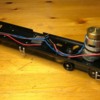
smoke filled room

Although the rebuilt smoke unit is still installed I had to unplugged it from power.  I’ll probably get into the shell again one day to install an on/off switch. 🙂

Attachments

Images (4)
  • smoke unit manifold
  • smoke unit mounted on stand
  • smoke unit installed
  • smoke filled room
Last edited by T.Albers

That’s phenomenal (not to say excessive) output, particularly from a smoke unit that has a 90 degree bend between it and the stacks. But of course it’s newly wicked and refilled with fluid, and looks to be operating on track voltage, so the volume of smoke will be at max.

I’m guessing that you didn’t drill a separate refill opening above the smoke unit and so the body shell will have to come off to recharge fluid as well as replace the wicking.

More importantly, I’m not sure which TMCC boards you are using if they are not ERR but most have a smoke power option that enables you to switch power on and off from the remote. Or is that not an option here? You mention they are older boards and I vaguely remember some made for diesels did not have smoke controls.

P.S. Excellent work on the brass tubing! I have resorted to using solvent- and heat-proof plastic tubing for the one thing I have done that is similar to this. That has three elbow joints in it, which reduces the pressure at which the smoke exits.

Last edited by Hancock52
@Hancock52 posted:

That’s phenomenal (not to say excessive) output, particularly from a smoke unit that has a 90 degree bend between it and the stacks. But of course it’s newly wicked and refilled with fluid, and looks to be operating on track voltage, so the volume of smoke will be at max.

I’m guessing that you didn’t drill a separate refill opening above the smoke unit and so the body shell will have to come off to recharge fluid as well as replace the wicking.

More importantly, I’m not sure which TMCC boards you are using if they are not ERR but most have a smoke power option that enables you to switch power on and off from the remote. Or is that not an option here? You mention they are older boards and I vaguely remember some made for diesels did not have smoke controls.

P.S. Excellent work on the brass tubing! I have resorted to using solvent- and heat-proof plastic tubing for the one thing I have done that is similar to this. That has three elbow joints in it, which reduces the pressure at which the smoke exits.

@Hancock52 You are correct I wired the smoke unit direct to the power pick ups on the chassis.  I mounted the body of the smoke unit lower inside the shell than the exhaust manifold.  The black tubing goes down hill into the smoke unit so I wouldn't have to take the shell apart to fill with new fluid.

If this TMCC board has a designated wiring terminal for the smoke output that would be great.   My hesitation would be to draw too many amps through a wrong terminal if it was only rated for a small LED.  I don't want to cook this working board.

Do you know where I can find a drawing of the output terminals for this 21 year old circuit board?   The board originally came out of my K-Line Union Pacific E8 "949" when it was being upgraded to ERR.  The set of locomotives was made in 2000 and the K-Line O-Scale Diesel locomotives part number was K-28901S.  I'm not sure if these photos will tell you anything but here's a couple shots of the stickers on the TMCC board when it was being removed.

K-Line TMCC boardK-Line TMCC board 2.


Thanks

Attachments

Images (2)
  • K-Line TMCC board
  • K-Line TMCC board 2
Last edited by T.Albers


(NOTE: I’ve amended my original post after some further checking.)

I don’t have a K-Line diagram, but I am sure that that K-Line board either does not have a smoke output, or if it does it may have been repurposed for motorized roof fans. The E8s K-Line produced at that time did not have smoke but the motorized fans feature instead. I have the Rock Island A-A set, which I have recently worked on to restore the operating fans in the trailing A unit. (I also remember that when you posted a photo of a UP E8 shell on another thread it had the K-Line roof fan mechanism in it with a rubber loop and pulleys, which can also be seen in your first photo above.)

BTW, the K-Line Legacy catalog shows the SKU you mention as an A-B-A (both A units powered) set with no smoke but eight motorized roof fans: http://www.legacykline.com/ord...p;p_oem_sku=K-28901S. Note that the text of this describes the set as having an E-unit, although I notice that two parts of the page heading refer to Railsounds plus TMCC. If it’s not TMCC, this could explain a difference between it and my E8, which answers TMCC commands, as yours does. On balance I think that this must have TMCC but an early version.

Anyway, I couldn’t quite understand the outputs on my E8 boards or why one of them had failed, and had to bypass it to get track power to the separate PCB for the fan motor. I think that you are right not to experiment with the outputs but someone more expert might tell you something different. Incidentally, although it may tell you something, the roof fans cannot be switched on and off from the remote; they are on whenever there is power to the track.

An entirely new ERR sound and control set would give you cruise control, a smoke output that could be controlled from the remote (as well as better E series sounds including crew talk if you want that), but that would not be cheap and ERR boards are sensitive critters! I suppose that, depending on how much room you have in the shell, it would be possible to install a Mini-Commander to provide smoke unit power and remote control, something I have done with dummy units - the M-C footprint and profile are really pretty small. But in your case a manual switch might do just as well.

Last edited by Hancock52

As @Hot Water mentioned above, my Union Pacific E9 was missing snow shields over its winterization hatches.  I missed this unique detail because it wasn't on the Locomotive Workshop's plans.  With further research I found these snow shields were added by Union Pacific in their shops after the E9’s left EMD.   Here’s a good write up from Utah Rails that covers the “when” and “why” Union Pacific decided to add this modification to their E8’s and E9’s:   https://utahrails.net/up/up-loco-features.php


To create new snow shields for my LWS E9 I started with a .01” thick brass sheet and a brass 1mm x 1mm right angle (code: A1 from Precision Metals).

thumbnail_IMG_9736


I couldn't find the shields exact dimensions listed anywhere but after searching my Union Pacific books and the internet I got pretty close.  First, cut a 34mm x 30mm piece from the sheet of brass, then bend the longer sides of sheet sides down 2mm.  Next, cut 3 equal size 24.5mm pieces of brass angles to replicate the welded angle irons UP used on top of the shield as stiffeners.

thumbnail_IMG_9734


With the right angle upside down, heat up a few small chips of solder with your micro torch and fill-in the empty V.  After cooling, file down any extra the solder that does not lay flat in the V.  Next, flip the brass angle over and place them in the correct locations on top of your shield.  Once in the correct locations, apply heat with the micro torch and the solder inside the V will melt and attach itself to the shield below.  Now you have 3 right angle roof stiffeners securely attached to the top of your brass snow shield.  

thumbnail_IMG_9737


Gently clean away any leftover oxidation with 0000 steel wool and then apply two coats of Tamiya clear gloss spray paint part# TS-13 to seal-in the brass finish.  Four thin strips of 2mm x 2mm of brass were used underneath each snow shield as support legs.  Now mount the finished product on top of your winterization hatches.

thumbnail_IMG_9772


Thank you Jack, this Union Pacific E9 looks better now.  Good eye!

thumbnail_IMG_9781


Also, as previously suggested by JohnBeere and Bob2, I finally had time to install a brass coupler on the front of this E9 (Precision Scale part# 40278).

thumbnail_IMG_9767


I’m still searching for an old Locomotive Workshop E9B shell to build/rebuild so I can have a matching B unit trailing behind this E9A.  I sent an email to @Jan K. Lorenzen.  He emailed back and said, he had a few brass parts from his dad’s LWS kits in the basement but no E9B shells.  If any forum members find an empty Locomotive Workshop E9B shell at a train show send me an email.

Attachments

Images (6)
  • thumbnail_IMG_9736
  • thumbnail_IMG_9734
  • thumbnail_IMG_9737
  • thumbnail_IMG_9772
  • thumbnail_IMG_9781
  • thumbnail_IMG_9767
Last edited by T.Albers

@mbw    Can anyone provide some advice on soldering copper wire to brass.  I have an old Western Hobby Craft Trolley.  The ground wire has separated from the brass motor mount. I already understand my soldering iron will not provide enough heat. I do have a micro torch, but am hesitant to bring in the big gun for fear of melting electrical connections close by. Thanks in advance on how to approach this problem.  I was thinking I could form a solder puddle on the brass and then solder the wire to the puddle.

I am comfortable with soldering copper plumbing, but this is far more delicate work.   

@Norton  I looked at disassembling everything, but I was concerned about breaking something. The motor itself had a bit of a standoff due to the mounting screws, so I did not think the heat would get to the motor or wires. I went ahead and used the solder tip which came with the micro-torch.  Cleaned up the brass, fluxed, applied heat to a pretty small area and got the solder pad formed. Then re-attached the wire using the torch tip. I was rather surprised the soldering iron (pencil) would not provide enough heat to re-attach the wire even with the solder pad down.

It must take a lot of skill and patience to solder these brass engine kits together. Hats off to you guys. Jeff 

Add Reply

Post

OGR Publishing, Inc., 1310 Eastside Centre Ct, Suite 6, Mountain Home, AR 72653
800-980-OGRR (6477)
www.ogaugerr.com

×
×
×
×
Link copied to your clipboard.
×
×