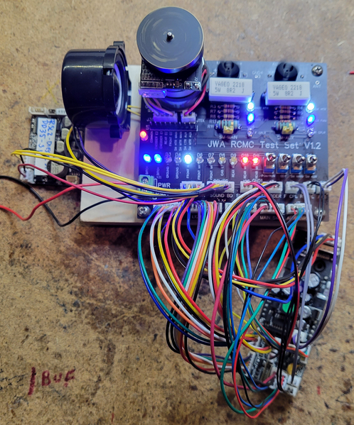
I've been thinking about this project for some time, but I finally got around to knocking it out.  This is an RCMC Test Fixture that is designed to test all the functions of either of the two first versions of the RCMC.  Those versions span from 2010 to 2019, I haven't looked at the latest version requirements.

<click on graphic to expand>

RCMC Test Set In Operation

Here's a plan view of the PCB that allows you to read the graphics more clearly.

<click on graphic to expand>

The Legacy motor with encoder is mounted on the board with connections for the motor and encoder provided.  Two complete simulated smoke units are provided with real smoke motors as some of the RCMC versions detect back-EMF and require a real motor to avoid an error shutdown.  All the lighting outputs are represented with individual LED's.  LED are color coded for quick recognition, red for rear markers, green for front markers, blue for ditch lights, amber for ground lights, etc.  Couplers are simulated by resistors as well.  Both the smoke unit functions and couplers have LED function indicators to provide visual feedback of operation.  A header is provided to connect a RailSounds Lite audio board, that facilitates operation evaluation as sounds are an important feedback for board operation.

A ten position header is provided with 'scope probe points to many of the most common functions that you might like to electronically monitor.

The test set has cables for both versions of the RCMC, with and without smoke thermistors.  That is required as some of the connectors changed sizes when the thermistor version was introduced.

Attachments

Images (2)
  • RCMC Test Set In Operation
  • mceclip0
Original Post

Replies sorted oldest to newest

@BillYo414 posted:

That's clever and probably really helpful compared to half assembling an engine a hundred times while you try to troubleshoot something.

Great job!

Thanks, that's why I built it.  Not only do you have to disassemble an engine, but you have to disassemble the right engine!  Some have one smoke unit, some have two.  There are also two types of smoke units, with and without thermistors, the connectors are different.  There are different connectors on the RCMC for different versions of the board, etc.

@Yendor posted:

You have been busy and must have spare time to play

Busy: Yes  Spare time to play: No

Simple logic, it's going to take me less time to verify function of these boards with a test set than having to take apart a locomotive.  I've gotten a few sent to me to test, but my testing is laborious if I have to disassemble a locomotive, not to mention finding the matching locomotive so I can do a proper test!  I've wanted to build one of these for some time, just decided it was time.

@Norton posted:

John, what connectors did you use on the board? Hopefully not JST EHs.

Well, there are a couple JST-EH connectors, most on the board are JST-PH, and the ones on the RCMC are a mixture of JST-EH (just one for power & motor), JST-PH (five on one version of the RCMC), and JST-ZH (most connectors).  There is also one Molex PicoBlade 1.25mm connector on the RCMC for the configuration switches.

I also bought pre-crimped wires for the JST-ZH and Molex PicoBlade connectors, those are a bit fussy and hard to crimp properly without the big buck crimp tool.

This is a question I have. Are Lionel engines spec’d out in house? Or does Lionel send pics of the locos they want built to their Chinese builders, and they design the engine’s electronic and mechanical features?

Dave Olson and others do all the design work in house, send the drawings to what ever builder,  China, Korea, or Vietnam.  Said builders will do a production sample to send to Lionel where Dave and crew will tweak the design, sign off on paint or what have you and give the ok to start production.

@coach joe posted:

John very nice job and an important piece of equipment.  So do you have to remove the board from the engine to test it? How do you connect to the board if not?

As long as the cables reach, you can just unplug them from the locomotive and connect the test set.  I actually have used it to just test lighting by only using the two lighting cables.  You can do the same for the two smoke units, the couplers, etc.  That works because what's on those connectors is isolated from the rest of the circuitry.  Most of the groups of functions are isolated when it comes to the external wiring.

I've been thinking about this project for some time, but I finally got around to knocking it out.  This is an RCMC Test Fixture that is designed to test all the functions of either of the two first versions of the RCMC.  Those versions span from 2010 to 2019, I haven't looked at the latest version requirements.

<click on graphic to expand>

RCMC Test Set In Operation

Here's a plan view of the PCB that allows you to read the graphics more clearly.

<click on graphic to expand>

The Legacy motor with encoder is mounted on the board with connections for the motor and encoder provided.  Two complete simulated smoke units are provided with real smoke motors as some of the RCMC versions detect back-EMF and require a real motor to avoid an error shutdown.  All the lighting outputs are represented with individual LED's.  LED are color coded for quick recognition, red for rear markers, green for front markers, blue for ditch lights, amber for ground lights, etc.  Couplers are simulated by resistors as well.  Both the smoke unit functions and couplers have LED function indicators to provide visual feedback of operation.  A header is provided to connect a RailSounds Lite audio board, that facilitates operation evaluation as sounds are an important feedback for board operation.

A ten position header is provided with 'scope probe points to many of the most common functions that you might like to electronically monitor.

The test set has cables for both versions of the RCMC, with and without smoke thermistors.  That is required as some of the connectors changed sizes when the thermistor version was introduced.

fantastic! !

Thanks Gary.  Once I launched into the project, it was actually not that hard.  The hardest part is understanding the behavior all the signals on/off the boards.  Fortunately, Bruk's document provided most of that.

I'm going to embark on a project to do an updated model that will test the newest Legacy boards, the LCP2 and LCP3 boards.  It looks to be about 80+ or so the same as the RCMC tester, so it should go pretty smoothly.

Post

OGR Publishing, Inc., 1310 Eastside Centre Ct, Suite 6, Mountain Home, AR 72653
800-980-OGRR (6477)
www.ogaugerr.com

×
×
×
×
Link copied to your clipboard.
×
×