
I was tired of waiting for Lionel to release their LCS Fastrack for AF so I decided to build my own.  I promised some others that I would share what I have done so far as I now have it operational,

Step 1: Acquire the O gauge LCS Fastrack

20151212_134855

Step 2: Note the two sensor positions (Black ovals) between the middle and top rails.  This position will not work for American Flyer as t will have to be centered evenly between the 2 rails.  Since O has 3 rails they needed to offset the sensor.

20151212_134956

Step 3: Make a template for the sensors on a piece of paper which you will use as your drill template.  Just place the over the track sensor and trace it.

20151212_135005

Step 4: Turn the track over and note the screw positions as you will need to remove them.

20151212_135139

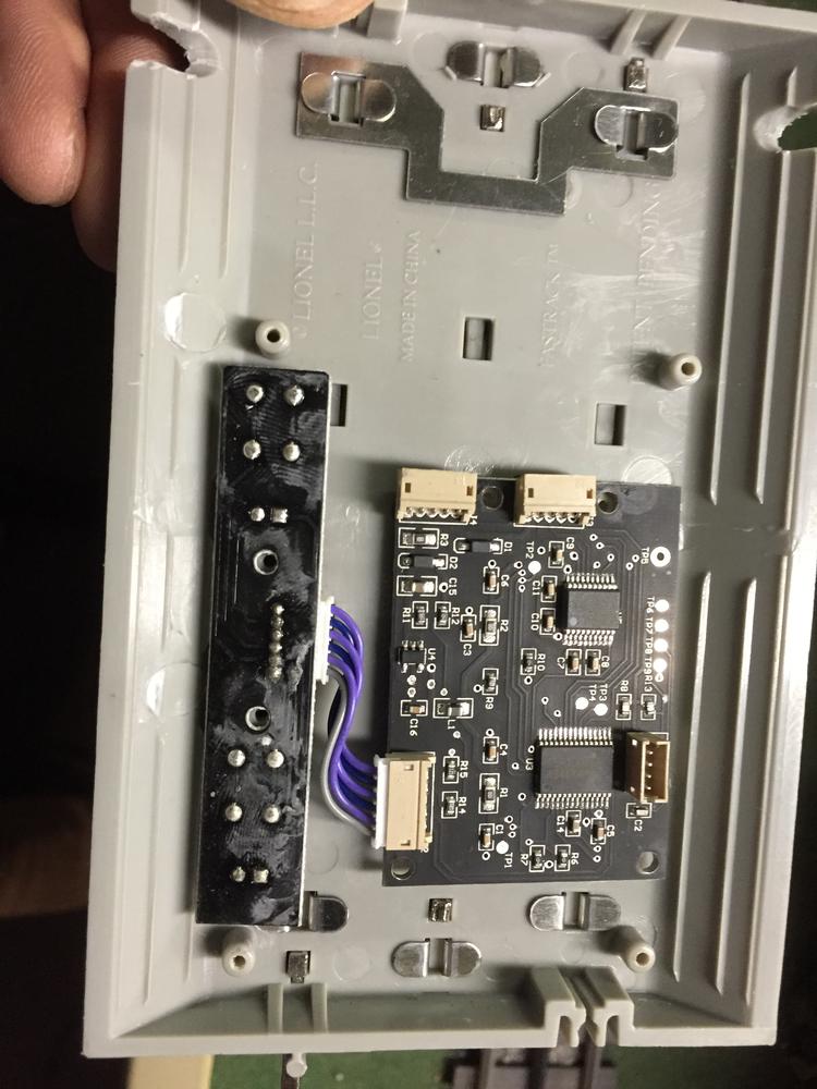
Step 5: Once the screws a removed then take off the back plastic cover.

20151212_135230

Step 6: Screws hold in the 2 boards.  Remove them and the boards will easily come out.

20151212_135514

Step 7: Use a dremmel tool (or other tool) to remove the support braces on the top and bottom of a 5 inch Fastrack section and the pre drilled nail holes.


20151212_141026

Step 8: Using your template from step 3 drill the 2 holes for the sensors.  Note they are in the center and I avoided the

track holes built in. 

20151212_144613

Step 9: Insert the main board aligned with the two holes you drilled.  In addition drill an outlet hole for the cable that connects tot he sensor track.

20151212_145852


Step 9: Note.  I stopped here as I need a ribbon cable that is longer than the one provided as the two boards can not fit in side by side.  Once I get this cable I can install the other board. 

20151212_152040

In the interim with the board sticking out this track works fine with the board on the outside.  The buttons all work ( I just covered it up for this Christmas.)  Just follow the instructions for the O gauge LCS track and everything will work just fine.

I will be happy to answer any questions anyone has,  Once I get a longer cable with the correct connectors I will mount the external board internally,


--Rocco--

Attachments

Images (10)
  • 20151212_134855
  • 20151212_134956
  • 20151212_135005
  • 20151212_135139
  • 20151212_135230
  • 20151212_135514
  • 20151212_141026
  • 20151212_144613
  • 20151212_145852
  • 20151212_152040
Original Post

Replies sorted oldest to newest

Rocco,

Nice job!  I admire the creativity and ingenuity shown to bash together a needed item.  If the factory won't make what you need, make it yourself!  One reason why my 1937 Ford has an IROC-Z drive train in it.

As to why Lionel doesn't make things like this, and many other things which are posted on another heading on this forum, I can only speculate.  It's been mentioned many times that what S needs is a reliable, full range track system.  Not just curves and straights, but curves and turnouts of more than one radius, sensor tracks, etc.  The new system is far from that.  Things come out piecemeal over a long period of time.  People need track on which to run their trains, and if it's not available, the trains won't sell.  If trains don't sell, the demand is lower, and the reason for more track is gone.  Vicious circle.  You have to admire the availability of trackage in O and HO, but I suspect it didn't happen overnight either.  Frankly, I don't blame Lionel too much.  S is a small segment of the hobby, and may not give a good enough return on any investment for the company. 

So in the meantime, keep it up Rocco.  By the way, do you have a source for the longer cord needed to mate the two boards?  It looks like a semi standard computer item.  There's a small electronic supply store close by that has just about every cord available but unless you live here in Southeastern Michigan, it doesn't do you any good... 


I will be taking down my Christmas layout towards the end of January.  Once I do I will post up a close up picture of the cable that Lionel provides to see if anyone has a source for a longer cable.  Once I get that then I will create part 2 of this post as I will fit the Program and record buttons into the track instead of outside the track.

--Rocco--

Rocco posted:

Yes the board will fit on the incline if I can get a longer wire with the appropriate connectors.


--Rocco--

From the view in your last picture I thought it looked like the wires were long enough to work, if that programming board would fit on the incline of the roadbed.

Kind of as it looked in the 3 rail piece.

Aflyer

The connectors used are called JST connectors, a generic term from the company that originally made them.

I bought a sensor track and took it apart because... Well, this is a great idea and maybe Lionel will make them if enough of us go rougue. Some detailed measurements led me to the ZH series. The datasheet is here:

http://www.jst-mfg.com/product/pdf/eng/eZH.pdf

I believe the part number is ZHR-6, which appears on page 2 of the datasheet.

The pins are purchased separately. The info is on the same page, as is the part number for the tooling to crimp them to the wire.

I'm going to do a bit more research to see if pre-made cables can be had. Lots of really cheap ones are on ebay, but you have to be careful because some of the connectors they call JST aren't, exactly.

Hope this info helps.

Nick C.


Add Reply

Post

OGR Publishing, Inc., 1310 Eastside Centre Ct, Suite 6, Mountain Home, AR 72653
800-980-OGRR (6477)
www.ogaugerr.com

×
×
×
×
Link copied to your clipboard.
×
×