Originally Posted by Trainman2001:

I don't know yet. About all I can say is over $500.00. We haven't had a complete production cut yet so I don't even know what the raw material and manufacturing costs are. It will be fairly priced for a complex, very handsome model of a rare prototype.

Hi Trainman and Andre, 


These are high quality works, so I would not dispute the price point, but it is a risk for a first time venture. I would have hoped for something smaller as a buy in and move up from there. Perhaps, the fire house I so want so bad would have been less expensive? (hint, hint)


Cheers,

-r


Andre's River Leaf already produces a very nice line of modest kits. I'm offering this as a not-so-usual, more elaborate one. I can also think about building the fire house kit, but it too has a lot of ornamental brick work that constitutes more time on the laser cutter and therefore more $$$. I'm looking to produce special, unusual and interesting models and Andre is going to help me do that. It's all very new to me so we'll see what happens.


Today I began construction of the main building starting with gluing the mid-partition wall, followed by the two rear side walls and then the rear wall. I used Aleen's tacky glue to hold it all together with various clamping schemes and right angle blocks to maintain square. 


IMG_3605


IMG_3606


IMG_3613


I like those corner clamps. I only have two of them and should buy more. They provide good grip and keep things square.


The windows will have to go in from the inside. This means that installing the second floor has to wait until the windows are in. This means that all exterior painting and grouting needs to be done before windows and floors get installed. That's why I'm building a pilot before writing all the instructions for the kit.


While this was drying, I turned my attention back to that ventilator master. I wanted to try and put the bevel in the master instead of cutting it on each resin casting. I used my Taig Lathe with the milling attachment. It took me some tries to get the milling attachment mounted in such a way that the cutter in the lathe's spindle could cut the entire face. I used the drawing I made to make a styrene template that I used to set the milling attachment angle. The set up was correct, but I was having difficulty holding the part firmly. 


IMG_3609


At first I was using a piece of brass to hold the work, but the bit kept binding, digging in, pushing the work out of position, and scaring the heck out of me. I then changed to a piece of key stock which was harder than the brass, kept trying to tighten it sufficiently, and getting the feel about how much material to take in each bite. I then decided to hack saw off most of the material since it was taking very long to cut the amount that I needed. I then remounted the work piece and finished the cutting.


IMG_3608


The results were pretty good!


IMG_3610


It matched the roof pitch perfectly. Only one slight problem... the stem was too short (or so I thought). If it's sitting flat on a surface, like a roof for instance, the wide portion hits the roof before the angle portion is seated. As I was explaining this to my wife she asked, "Don't you check twice before cutting anything?" Of course she's right, but not in this case. What happened in this case was the drawing itself that I made was wrong. I didn't make the stem's dimension long enough. So what to do? I really didn't want to make another one of these. It took over an hour to cut that bevel. So I'm going to machine the o.d. of the top part a bit smaller (about .825") so it will clear. If I can, I'll reduce the o.d. of the stem too so make it more proportional.


IMG_3612


I could simply add a block underneath to raise it a bit on the roof. When I re-checked the drawing, I drew a line from the bevel to the cap and it intersected it just like the one I made did.  Tomorrow I keep building the structure, fix the vent and maybe start doing the resin casting.

Attachments

Images (7)
  • IMG_3605
  • IMG_3606
  • IMG_3613
  • IMG_3609
  • IMG_3608
  • IMG_3610
  • IMG_3612

Moving right along on the distillery pilot...


Put on the remaining walls only to find out that there's something wrong with the front wall panel. It's too wide by about 3/64" and the error shows up in the spacing of the right side's slots for the side wall tabs. They were that same distance too far right. Then when I added the trim, the left side had a gap of that same 3/32" to the left edge. The distance from each slot to its side edge was the same, so the problem lies in the front not being correctly centered. 


IMG_3614


 To make the front fit, I had to cut the 1/8" from the inside edge of the right side slots. 

IMG_3617


While this was drying, I decided to try and modify the aluminum vent master. I was able to chuck up the shaft end and turn the vent head down in both diameter and height. And then turn it around and carefully turn the shaft end down a bit to get the proportions back in line. Because of the angle cut, the cut was interrupted which makes it even more nerve wracking to turn it without causing any calamities.


IMG_3615


The result is a vent master that now sits properly on its tapered end and will sit correctly on the roof.


IMG_3616


Back to the building...


With the walls dried enough I started putting in some of the 2nd floor supports and the front and back brick trim. I had to move the middle vertical supports on the left side about a half inch to the right on both the first and second floors because it is too close to the window and would make it difficult to install those windows. I've re-designed these supports on the master plan so it will be properly cut in the future.


IMG_3619


The back trim went on nicely except I now realize that it was foolish to make it in four parts. This makes for some unsightly seams. In the future that will be cut as a single piece. The back trim had a similar error as the front with the trim not fitting flush on the right side. I've got to go back and review the geometry on these pieces.


IMG_3620


I have extra pieces from the first cutting so I carefully made an extension piece to close the gap AND provide the extra overhang with the mating corner bevel.


IMG_3622


Clearly, that seam will be hard to hide and won't be repeated in any future kits. I was explaining to my wife how difficult this. If I was scratch-building this structure, I would cut and measure the trim directly from the model. If the sides were different, it wouldn't matter. It would all be custom fit. With laser cutting, all this has to be worked out in detail holding tolerances to less than 1/32". I would be like pre-cutting all the crown molding for a house based on the floor plan drawing and not measuring each room as you go.


Here's the front wall with its trim added.


IMG_3623


And lastly I added the brick trim around the door only to find that I had to remove a bit of the trim applied prior to the door trim.


IMG_3624


Even with all these little annoyances on the pilot, it's going to be a terrific building with great drama. Meanwhile, I'm continuing to develop the instructions.

Attachments

Images (9)
  • IMG_3614
  • IMG_3617
  • IMG_3615
  • IMG_3616
  • IMG_3619
  • IMG_3620
  • IMG_3622
  • IMG_3623
  • IMG_3624

Mark, I think you're right.


The updated crenelations cut came today from Andre. Of course as I was assembling it I found that I drew the top layer wrongly and was able to trim it to fit, and will change the master drawing. I'm now at a point where I can take as-built measurements directly on the model. By the time I'm finished with the pilot, the drawings will be as precise and accurate as I can make them. I'm also developing some different strategies as I see how the building is actually going together. The biggest challenge is due to the nature of the Masonite we're using. It's only finished on one side. The other side is too rough to engrave with bricks. Most of the model doesn't have many places where bricks are on both sides of a wall, but there are those places. This is especially seen along both sides of the roof parapets, and the back sides of the brick end walls that extend past the side walls.


I got almost all the exterior trim installed, making custom corrections where needed.


For example: in this pic, I will make this backup trim piece extend below the roof line ad then reduce the roof's width the proper amount. That solves the problem of the roof fitting exactly under the trim piece.

IMG_9729


In this instance, the trim piece width for the center wall is one ply thickness narrower that the trim piece at the front corner. I didn't realize this when I drew the parts. I will now have trim parts specifically sized for each spot on the model.

IMG_9730


It's coming along...

IMG_9731


Here was gluing the first crenelations assembly to the building. It looks very close to the image in my mind.

IMG_9732


Next session I'll be adding the rest of the trim and then the building's body will be ready for paint and brick detailing. I think I'm going to include some engrave plywood sheeting so the builder can fabricate his/her own parts if anything gets screwed up. I'm been using engraved pieces from the first cutting to correct any mistakes I've found.

Attachments

Images (4)
  • IMG_9729
  • IMG_9730
  • IMG_9731
  • IMG_9732

I missed yesterday's post so today I'm going to delve more deeply into creating all those brick ornamentals. It was a while since I made the drawings and I ended up getting some things wrong based on my original design. It all will work out in the end since I'm making real-world corrections as I go. Needless to say, it's a complex and satisfying puzzle to get all this 3D effect out of laser cut flat pieces.


The main crenelations were fixed and I did change the drawing so the top piece is correctly shaped. They lined up nicely.
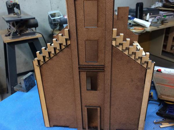
 

IMG_3685


The corner "Castles" (I don't know what else to call them) were challenging since the balusters should have been cut from 1/16" and multi-layer. Instead, I had specified 1/8" so I couldn't assemble the with the same relief. I also glued the balusters too low on the base piece, not paying attention to my own drawing - DOH! Regardless, they look okay. The body pieces should have been 1/8", but I had neglected to draw them. So I used the 1/8" pieces that were supposed to be used for the upper works pieces. I then had to use 1/16" stock for those. All will be corrected!
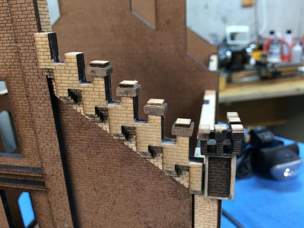
 

IMG_3693


I'm changing the size and shape of the castle overlays. I also speced the wrong size of the first level caps and used extra 1/8" stock to cut correctly sized top caps.


For the upper works I used the miter technique and it worked great. I made a square column with 1/16" pieces and then applied the overlay pieces. They get placed only on the outer corners. My Chinese 1" belt sander died yesterday. One minute it worked and then the next, nothing, nada. The switch felt funny and I think that's what failed. I took the cover off the electrics and it's a capacitive-start motor. I don't know if it dies if the capacitor dies. I needed it to shape the miters. I need to find someone to repair it without charging more than the original low price.


I had my dad's woodworking vise sitting on a shelf in the store room and decided I'd finally mount it and then put my belt sander in it upside downs. This actually worked well and I was able to shape very respectable miters.
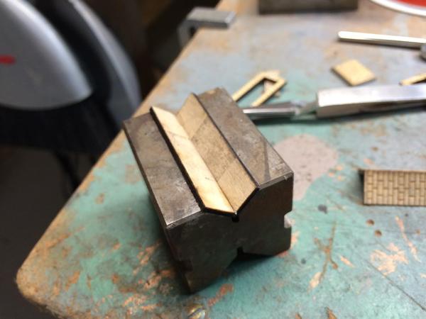
 

IMG_3696


I glued the miters up in pairs using a V-block as a fixture. I used a bit of thin CA at the first end, went to the other and ensured alignment and added another bit of CA. I then filled the rest of the joint. I took it back to the belt sander and sanded the opposing miters simultaneously. I then joined the two halves.


This picture shows the second one with the 1/8" piece as it should have on at least one face.


IMG_3700


Notice the seam down the middle of that back piece. That's because I ran out of brick engraved material. As it was this piece should have been made with 3-sides of 1/8" material with the back side open. Instead, I forgot and used the thick material for the castles. Oh well...


As it was, the parts of the main building that support these towers was also sized for the 1/8" thick material on 3-sides only (the back is open), so when I put the tower made with the thinner stock onto the building it needed to be packed out with 1/16" material. I wondered how I could have gotten it so wrong, but I didn't get it wrong. I had designed the whole assembly for the thicker material. It was when I forgot my own design that the trouble began.
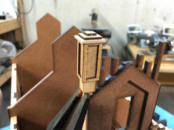
 

IMG_3699


The lowest piece of the top cap in this instance was also sized incorrectly so I scratch-built a new piece and will change the drawings. I held the tower in place with Gorilla Glue since there were still some loose clearances and I wanted the glue to take up the slack.


I think in the kit, I'm going to include some extra trim pieces and some engraved 1/16" material so the builder can make or remake any pieces that got screwed up. We're all human.


In a few more days, all this ornamental work will be done and I'll be ready to spray the primer and do the brick treatment. I started to check the fit of the roofs and the clerestory walls. They fit!


I also need to re-design the front walls parapet to make them higher, as high as the other two end walls. I don't know why I made them so low. I think I was afraid it would interfere with all the ornamental work. It won't and it needs to be higher since it's actually sitting lower (by a bit) than the roof piece itself.

Attachments

Images (5)
  • IMG_3685
  • IMG_3693
  • IMG_3696
  • IMG_3700
  • IMG_3699
It's a 30+ year-old Taig with accessories. I have the compound slide, milling attachment, ball turner, 3-jaw chuck, plain faceplate, tailstock and a set of carbide 1/4" insert tools from Harbor Freight. While it's a good machine, it's very light duty. You really can't take cuts much over 0.040". The compound slide's locking mechanism is dubious at best and I'm only using it when I'm naking tapered cuts. If I were to do it again today, I would get something a little more robust. As it is, I've done some valuable work with it.

The ornamental brickwork is complete, and despite my getting a couple of this a little off, it looks like the photo.


IMG_3711


Here's a comparison:


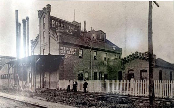
Original Berheim Bros Distillery


While it's not an exact duplicate, I think it's really close and captures the ornateness of the original well.


It still bugs me that I glued the corner castle tops too low and used CA so I'd wreck them to try and get them apart, so they're going to stay the way they are for my pilot and will be fixed for the one I build for Heaven Hill's visitor center.


I bought another 1 X 30" Harbor Freight belt sander to replace my dead one. At $44, it really isn't worth the cost to have someone repair the other one. I'll pull the motor and maybe apply it someday. It will give me replacement parts for the new one. I also bought a another digital caliper since my 10 year old one is getting beat up. The points are not longer sharp nor accurate and I use it constantly for scribing off exact distances. I bought a very inexpensive combination square and some small ratchet clamps for $0.99. How can you go wrong for less than a buck a clamp. I'm going to get more of them.


The center ornament was mitered with the help of the new sander. I was able to set the tilt table to 45 degrees so it made putting in the miters very easy. 


IMG_3703


I had to make a perfectly square filler piece which formed the top of the body. On this sits a stack of a two-layer pyramid. A larger square goes on the bottom as a base. Here it is installed.


IMG_3704


Next up were the little overlays and pyramid tops for the remaining top ornaments.


IMG_3708


I'm still impressed with what can be done with flat, laser-cut materials. It's all in the designing.


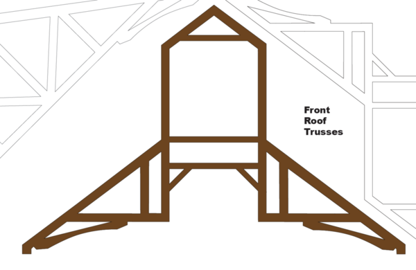
After this was done, I started to work on the clerestory top to the building front half. I needed to redesign the truss system to both add support and locating ability to the clerestory sides and roof, AND to get the trusses out of the two top front windows. I knew these would be in the windows in the SketchUp design. 


Using the existing truss design I cut it apart, scavenged some similarly sized Masonite from the frets, and cobbled a new version. I then took this idea back to the computer, drew it up and made a paper mockup to see if it worked. It did, so I transferred the drawing back to the master set.


IMG_3710


You'll notice a cross piece still bisects the window. That was removed after I added more lateral reinforcement.


Here's what the final version looks like.


Screen Shot 2015-07-24 at 11.34.28 PM


While doing these changes I went back and re-checked all of the roof components and made some more minor tweaks to get it all lined up. Laser-cutting makes beautiful trusses.


It's the weekend, so no more shop work. I now have to decide when to paint. I may finish the clerestory and the other dormers separate from the main body since they all have to have the roof pieces on the building before installing them. I don't want to paint the roofs and it's easier to add the Rusty Stumps shingles when the roofs are flat on the work bench. By finishing these parts off the model, it does make neat gluing a key factor.

Attachments

Images (7)
  • IMG_3711
  • Original Berheim Bros Distillery
  • IMG_3703
  • IMG_3704
  • IMG_3708
  • IMG_3710
  • Screen Shot 2015-07-24 at 11.34.28 PM

It's Monday, so after working out on the equipment I was down in the shop.


I finished cobbling together the modified trusses and then went back to adding parts in prep for painting. The parts were all the sills and lintels. I realized that I hadn't drawn any for the front windows which are different than all the rest, but I had extra long lintels for over the loading door and cut them down to size. I then added them to the drawing set.


I also am concurrently working on the roofing. I'm still working on the assembly procedure. You can add the downstairs windows with the 2nd floor in place. And you can't add the roof without the 2nd floor. So the routine will be as follows, all brick work will be grouted and aged before any roof or windows are in place. I'm going to make the roofing removable, although I'm not sure why since LED lighting, once tested and installed will probably out live me. As I noted before, it's much easier to do the roofing shingles when the roofs are off the model. But I did build the clerestory roof today.


IMG_3715


Lintels really dress up the building. I think on my next project, I'll include the lintels in the brick engraving. There are some standing buildings in town that have similar windows and brickwork as the Bernheim Distillery and I may use their brickwork as a model for future projects.


IMG_3717

IMG_3716


I'm finding that a combination of Aleen's PVA and CA really holds these parts together. I start out with the Aleens and then add the CA. Because of the water-based glue, the CA kicks quickly and binds the whole deal together. The added reinforcement really strengthens the assembly.


To put really nice bevels on everything, I reset the table on the NEW belt sander to the exact angle that each roof halve needed. After sanding the bevel, I used a sanding block to ensure that they were straight and uniform.


IMG_3718

Attachments

Images (4)
  • IMG_3715
  • IMG_3717
  • IMG_3716
  • IMG_3718

Thanks Pat! It's been one heck of a learning experience for me too. Glad I can share it with others.


Today I did some more work on the roofs and finished adding any missing overlays in prep for painting. And then I found that I completely blew the dormer design that goes from one side to the other. I will redesign so all future versions are correct. I seriously thought that I had the geometry correct. Go figure?


IMG_3728


The above shows two specific details. First the overlays for the chimney are one and fit perfectly. Then I added the medium width side trim to the upper works. The I trimmed and sanded the upper edge to conform to the roof pitch. Topping this will be some parapet capping. The chimney gets capped with a plinth that will have holes drilled in it for the two stacks that emirate from it.


One of the problems using slot and tab construction on thick pieces is the end grain that isn't engraved. One way around this is to go back and scribe the missing bits so when painted, you won't notice the glaring change in texture. Masonite end grain is rather soft and doesn't take scribing well so I harden it first with a layer of thin CA that absorbs and cures quickly. It seals the texture and provides a smooth surface that takes scribing pretty well. I used my digital caliper to do the scribing. 


IMG_3734


Here're are both dormers in place on the rear roof. Notice anything?


IMG_3726


The small dormer roof is supposed to intersect with the main roof peak. I made it so the dormer sides intersected with the roof forgetting that the roof peak is significantly higher. In this picture, the big dormer is glued to the building, but its roof is not attached yet. The small dormer is not glued down, but its roof is. I wish I hadn't jumped the gun and glued on the big one since I want to scribe the bricks on the tabs and it's made more difficult with it being hung on the roof. On this model, the "wrong" dormer design will have to stand, but I'm fixing it on the drawing after I finish writing this.


I'm also going to specify thinner stock for the small roofs since they don't have to be so bulky. With a fascia board you won't know how thick the roof is. Thinner material will be easier to bevel with non-power equipment. They would also be easier to glue together with the underneath supports.

Attachments

Images (3)
  • IMG_3728
  • IMG_3734
  • IMG_3726

Of all the projects I've done, this one truly has the most learning richness. I'm happy that all you folks appreciate that too.


Today I turned 70! And if I can learn all this new stuff at this "advanced" age, so can all of you. I am still learning new stuff constantly. As long as the eyes and hands hold out I'm good to go. Never being a jock, my hips, knees, etc., are doing great. The hands, on the other hand, are showing the wear and tear of 62 years of model making and guitar playing. My theory is whatever you use most wears out first. My orthopedic surgeon son in law disagrees with me saying he has patients whose hands are a wreck and the most they do with them is operate a TV remote. We agreed to disagree.


Now to today's work.


I re-designed the gable roof system last night. I was able to take direct measurements of the gable roof panels from SketchUp. You simply orient the view so you can see the roof panel and using the tape measure tool, directly measure the roof. It was full size so I divided each measurement by 48 and used this to draw each roof piece in scale in Adobe Illustrator.


I printed these new parts today and attached them to matte board with some spray glue. I figured I'd mock up the gable to check to see if it works. It did!


IMG_3746


Since I now had two perfectly fitted templates, I decided to take some 1/16" ply and make new roofs and rebuild the whole deal so the prototype would be right. I had to detach the bad roof from the gable pieces, and I had to remove the tabs since the roof slots were no in the wrong position. I wasn't going to cut new slots so I would just flush glue the gable to the main roof.


The gables needed a bit of reinforcement on the back end so they would remain square.


IMG_3747


Like before, I used the belt sander with its table set at the roof pitch angle to sand the roofs' mating edges so they'd glue up correctly. By using 1/16" inch ply, I was now able to actually install proper fascia boards. With the thick 1/8" material, the roof thickness was as wide as the fascia boards and why would be redundant. That angle reinforcement really helps in gluing up the roof. I'm going to include that in the laser cut pieces.


IMG_3752


To ensure that the peak end of the roof would conform perfectly to the main roof, I used my sandpaper-on-plate glass tool to sand that angle perfectly flat.


I hand fit the gables to their new location and marked the roof with a Sharpie, then glued gables down using Aleen's PVA. 


IMG_3749


From the above you can see the new position is almost an inch below the roof crest. When the roof is shingled all of these openings will be concealed.


And here it is with the roofs just fitted. I can't glue them down until a) the bricks are all painted and grouted and b) the windows are installed since they go in from the back. I'll shingle all the roofs before installation.


IMG_3750


IMG_3751


That problem is solved. Tomorrow, I'll add the brick engraving to the larger dormer and get ready to paint the Rustoleum Red/Brown primer.

Attachments

Images (6)
  • IMG_3746
  • IMG_3747
  • IMG_3752
  • IMG_3749
  • IMG_3750
  • IMG_3751

Good its not midnight yet! Happy Birthday!

You needed the firehouse & equipment to meet city code for the candles right?


Just wait till its done outside to avoid the flame heat.

(not much left of the cake top either with 99 candles on Gramps cake.)


For he's a jolly good fellow!.....And many moooooooore....


   What? Its the only party hat there.


(Yep, I'm still here. I like to save this thread and read lots at once. Carefully)


You're welcome. All birthdays from this point forward are "great ones." We celebrated with half of my grandchildren, so that was special.


I only got an hour in the shop today. I trimmed a bit from the main roof since it now needed to clear more brick trim on both ends. I also started to attempt to fill in the excess space on the mid-wall brick trim. Unfortunately, I'm just about out of extra engraved material and am cobbling together some filler pieces. On the production version, this trim was already re-drawn to fill the gap. But this is my pilot and I wanted to make it as best as I can.


Here's the ugly gap.


IMG_3756


And here's an even uglier cobbled together pieces of brick material that will fill the gap. 


IMG_3755


I'm gluing all the pieces on a piece of paper to hold it all together. I'll true all the edges and then glue it under the existing trim. I will be impossible to see on the layout since it's the back of the mid-wall and will be facing away from viewers. (But I will know it's there). For the display version that will go in Heaven Hill Distilleries Visitors Center, that's a different story. I'm not sure how it will be situated and have to assume that all sides will be viewable. I'm also thinking about doing more landscaping and making it somewhat of a diorama.


I finished scribing the brick lines on the big roof house's tabs. I'm glad that's done.


Weekend coming and that's a non-shop-work time. Monday, I'd like to get the paint on. We're then taking a short vaca so the paint will have a lot of time to cure.

Attachments

Images (2)
  • IMG_3756
  • IMG_3755

I'm a little late to the party...it took me two days on and off to go through your posts, click off a like or two, join you as a follower; sorry about those automatic emails!


Happy belated birthday. I hope to retire in 7 years. I hope that I have at least half of your energy when I get there.


Amazing craftsmanship and your attention to detail blows me away...


Tom

Last edited by PRR8976

"Better late than never" I alway say. And thanks for the B-day wish. My energy comes from being retired and my only "job" is to build a great model railroad. My wife chides me constantly when I say, "I have to go work in the shop". She insists that building my trains is not "work", but is my hobby. If I go on to sell some kits from these projects, then I can accurately call it "work". Until then I have to agree with her. I'm never sleep deprived any more. I never get up with an alarm, so instead of 6:15 a.m. as it was when I worked, it's now somewhere around 9:00. That makes a huge difference. Plus no more 45 minute to 1 hour commutes to work. All in all, if you can keep busy with something you love, retirement is wonderful.


I just stopped in the shop a minute ago and checked on that cobbled filler piece. It dried well with the paper backing and I just tried it in position. I didn't true the edges which would further reduce any obvious gaps. I just stuck it in there to see how it worked.


IMG_3757


As far as I'm concerned, after sanding, fitting, painting and grouting, it will look acceptable. The back wall inner parapet isn't finished with brick either. I designed a piece for it for the next iteration. I don't have any more brick material to fill it with, and I don't want to spend the time scribing some styrene (but I might). You don't see the entire wall since the middle part is occluded by the big gable house. You do see the parts on the slant roof. Now that I think about it, I probably will scribe some 0.010" styrene to cover the bare Masonite. I'm thinking too that I'm going to spec the 0.024" laser-board instead of the 1/16" ply for all the trim cover pieces. The thickness is really a detriment in this application. Unless you're going to bevel and match the edges, which I am going to do in more places, the thinner the material the better.

Attachments

Images (1)
  • IMG_3757

Merci Beaucoups mon Ami. RC Scalebuilder.com is a model RC airplane site that has some of finest builders in the world (seriously!). They write build threads that last for years, kind of like this one. I learned how to do this from them. I was commissioned to build an RC B-17 bomber and hadn't built a flying model in 25 years. I found that web site, read many threads from beginning to end and learned how to build again. I'm paying it forward.


Today was a milestone day. I got the paint on. We're going to Chicago for a couple of days so it will have time to dry well. Before taking everything outside I finished that cobbled trim piece and figured a jerry-rigged way to brick the one remaining wall. 

 IMG_3760

Even there are those ugly gaps, when grouted, it won't so bad. The corrected trim is already on the drawings.


I bought some MicroMark textured, self-adhesive, brick paper 10 years ago when I built the Sterling Tower. It's the same scale, although a more red than the Rustoleum that I'm using. I'm hoping that a little weathering/misting of darker red will make it match decently.


IMG_3759

This saved me hours of scribing styrene. As I've noted many times before, I'm having these trim pieces cut in the next iteration.


I also cut and sanded some small wedges to fill the small gap that still existed under the small dormer front. This too is corrected on future versions. 


I made a "concrete" piece that caps the chimney bricks that will accept the stacks. The two 3/16" holes came out a little large. I'm going to spec a smaller diameter to make the fit tighter.


With all this out of the way, and with perfect hot weather, I took everything outside and painted the brickwork throughout. I like how it looks with everything the same color.  


IMG_3764


These are the clerestory sides and are also brick engraved.

IMG_3763


It's an imposing Victorian structure. There are still some existing building in Louisville with similar details as this one. I'm going to seek them out and possibly design some others.

IMG_3762


In this pic you an see the filler pieces that closed the gaps under the gable wall.  


IMG_3767


When I'm back in the shop on Friday, I'll give it all a coat of Dullcoat, and then start grouting. Grouting should take a few days...there's a lot of bricks. I'll also airbrush the windows and stain the doors. All of sudden I'm seeing the light at the end of the tunnel and it's not a locomotive... I hope.

Attachments

Images (6)
  • IMG_3759
  • IMG_3760
  • IMG_3764
  • IMG_3763
  • IMG_3762
  • IMG_3767

The trip was great! We walked almost 10 miles, but I still gained two pounds. Eating differently (and better) works against my desire to maintain a lower weight. I am happy though that since actively engaging in less eating and more moving, I'm weighing just 18 pounds more than I did when I got married... and that was 1968. I was 155 then and 173 now.


We had a chance to get to the Chicago Museum of Science and Industry and spent time drooling over the massive HO layout they built in the train room. If you haven't seen it, I'd suggest putting it on your bucket list. Here's a sample:


IMG_3884


The Willis Building (nee Sears Tower) looks like it's actually scaled correctly.


IMG_3893


They have a  full-length Burlington Zephyr streamliner on the lower level near the parking garage. You can look inside the power car and see the Winton Diesel and the operator's cab.


IMG_3906


While the outside was sleek and streamlined Art Deco Budd Stainless Steel, the cab looked like it was something out of the 19th Century. Not only did it appear crude and cluttered, the engineer's and fireman's compartments were not adjacent with the switchgear seemingly blocking vision from one side to the other.


IMG_3907


The weather in Chicago was wonderful and the James Hotel also very nice. We try to get there at least once a year.


I was fully prepared to start applying grout to the brickwork today. But then I noticed that I hadn't put the sills and lintels on the dormer windows, and forgot the sills on the front windows. Since these needed to be painted I did the gluing and painting and they'll have to dry over the weekend.


IMG_3912


I also filled the space at the front slot/tab from the floor. A piece of Laser-board was the perfect thickness and I applied that and then scribed the brickwork on it. It took the scribing well and looks pretty good.


IMG_3911


It looks so nice that I'm going to specify laser board inserts for all the base plate tab openings. I'll make the tabs one-laser-board-thickness less deep to leave room for the filler piece. I'll have Andre engrave a strip of it and the builder can cut off the pieces to fit the specific openings. This will be easier on all than making individual fitting pieces that need to be kept straight.


I also sprayed all the windows with the Pennsy Green to match the kitchen windows.


IMG_3915


And I stained the doors Minwax "Jacobean" stain. It's a bit darker than the oak I used on the kitchen door.

IMG_3914

 I went shopping today and got more Rustoleum 2X Red Primer, some sand paint, and then went to Michael's and bought a pair of pinking shears. I was thinking about how to make the flashing that's going to go on the roof edges and realized that pinking shears might just make this process much easier than cutting the saw tooth pattern with the Xacto.


IMG_3910


And here was a sample I made in a second or two.IMG_3909

The actually piece will be a bit narrower than this test and I'll probably paint some gloss black lines that would indicated separations between them, but the idea works. I also gave a light primer spraying of the brick paper on the back wall to match its color better. It will look pretty good when the parapet capping is in place and the bricks are weathered a bit with the wash.


By the time I got this done it was dinner time and time to quit. I'll get back to work on Monday.

Attachments

Images (10)
  • IMG_3884
  • IMG_3893
  • IMG_3906
  • IMG_3907
  • IMG_3912
  • IMG_3911
  • IMG_3915
  • IMG_3914
  • IMG_3910
  • IMG_3909
Last edited by Trainman2001

Finally got into the shop this week. Didn't have too much time, but I finished one of the small roofs by adding the fascia boards and then started to 'mortar' all the brick work.


IMG_3942

The material used for this was the laser cut 1/16" ply, but I'm going to either specify 1/32" ply or Laser Board since this material in real life wouldn't be 4" thick stock. You won't see the thickness since the shingles are going to go down to the edge and cover the edge grain.


I started applying the joint compound on the gable walls since they're small and easy to do and I didn't have much time. I used my new plastic painting knives that I bought at Michael's several weeks ago After slathering it on and scraping off the largest excess, I used a single-edged razor blade to scrape off even more. After this picture was taken I used a damp paper towel to clean off the surfaces some more. It really needs the alcohol/india Ink wash...


IMG_3943


I then started the building with the ornamentation. It's the most annoying to grout since you have to do dental work to level and clean all those little spaces. This is how far I got.


IMG_3944

Tomorrow I will be in the shop for a long period of time and get some major grouting done.


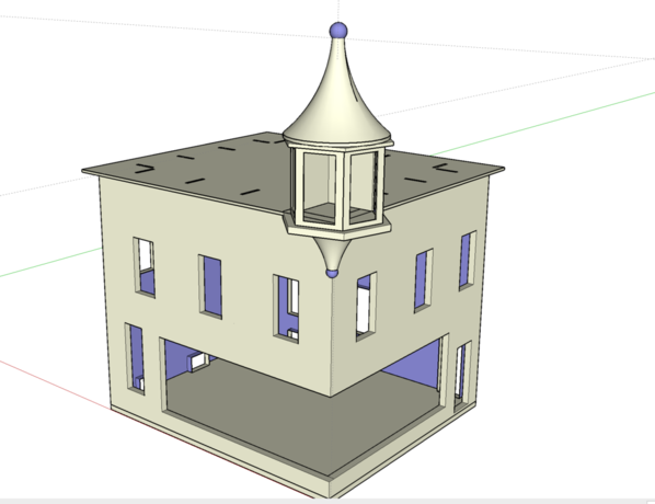
While not building the prototype, in the evenings, I'm working on the laptop writing the assembly instructions and doing some other building. In the case of the Night Hawks Cafe, I started with the orthographic projection and imported views into SketchUp to produce the 3D drawing. It's actually fun building a virtual building this way. Here's what it looked like on my screen.


IMG_3945


Since I took that picture, I finished developing the top and bottom turret details.


SketchUp has a "Follow Me" function that enables you to establish a path and a profile and then the program generates the 3D shape. It's like magic. That's how the top and bottom domes were created. All I needed was the profile of the curve and the circle around which it was to be generated and, POOF!, there's the domes.


Screen Shot 2015-08-12 at 10.59.08 PM


Notice that the sub-roof piece has the slots that will accept the mansard roof formers. In this way, I can literally pull the building apart to create the assembly drawings. Instead of spending the time to generate the spheres on the top and bottom, I simply went to SketchUp's 3D Warehouse and found on that would work. I just had to scale them to fit the building. At first, I was doing the drawings with tabs and slots for the main walls, but it creates some much extra work to hide the tabs, that I'm designing it now for mitered corners where the brick work meets perfectly. The belt sander and its adjustable table makes shaping accurate miters not so onerous. The building would need some square stock reinforcement in the corners to add some strength lost by losing the tabs and slots.

Attachments

Images (5)
  • IMG_3942
  • IMG_3943
  • IMG_3944
  • IMG_3945
  • Screen Shot 2015-08-12 at 10.59.08 PM
Last edited by Trainman2001

Thx! I'm having a problem with SketchUp when I punch the window openings through and then erase the piece in the middle, the entire back of the wall disappears. I'm doing something wrong when I do the push pull. In this instance it doesn't matter too much if the back of the wall is there as long as the wall thickness appears in the window opening. Any ideas?


Today, I got into grouting the main building in earnest. Here's the tools I use for the job.


IMG_3950


I squared off the end of one of the plastic palette knives to use as a narrow scraper. I also use the razor blade for this purpose for big flat areas and the two dental tools to get into corners and crevices. 


Here's the mess that you get when you first apply the joint compound. It looks hopeless, doesn't it?


IMG_3948


After a couple of hours of smearing and scraping, here's what the front looked like.


IMG_3951


I spoke with my friend Ashe Rawls last night and he suggested not using paper towels to wipe off the excess, but to use pieces of cotton sheets. He said using T-shirts is too soft and it will reach into the grooves and remove too much grout. I took his advice and here's the front after the excess has been wiped off. He also suggested another way to use the joint compound, by diluting it and brushing it on. He generally tints his grout using acrylic paint. I find that the grout tends to tint itself from the red bleed I'm getting from the Rustoleum primer I'm using. Once the black was is on, the grout is no longer white nor bright.


IMG_3952


It's now waiting for the rest of the building to be grouted before using the alcohol wash. I started on the right side and was pleased to see that the ugly seam is not going to be too noticeable. The latest versions will be all cut from single piece stock so this seam won't be there. I knocked off one of the tops of the high spires. I've glued it back on once I finished all the scraping on the front.


IMG_3953


I'm glad I did all that tedious ornamental work first and got it out of the way. The rest of the building, except for the chimney, is mostly big flat areas or narrow flat areas and goes pretty quickly. I'm thinking seriously of drawing the lintels over the windows into the brick design so they're flush. In many building this fancy brickwork does not stick out, and it makes it much easier to add group. The window sills, on the other hand, do have to have some relief.


There's a good chance I will get the grouting done tomorrow, or at least on Monday. Then it will be time to build 26 windows. I will also be working on the interior lighting of the main house.

Attachments

Images (5)
  • IMG_3950
  • IMG_3948
  • IMG_3951
  • IMG_3952
  • IMG_3953

Hello,


Ihave seen on your picture that you have no thickness for the walls and you have it  for the windows; there was a mistake I made at the beginning. There is a simple way to repair; I can show you how to do, but before, let me make some drawings to explain you the way I use to have correct openings for windows or doors, OK?


See you soon


jpv69, frenchie sketchup'er!!!

Add Reply

Post

OGR Publishing, Inc., 1310 Eastside Centre Ct, Suite 6, Mountain Home, AR 72653
800-980-OGRR (6477)
www.ogaugerr.com

×
×
×
×
Link copied to your clipboard.
×
×