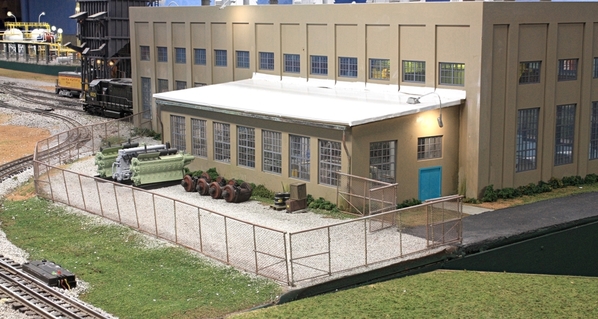
The work benches and the rest of the shop shown looks great! I like symmetrical as well, putting a window on either side of the tower just makes sense to me. That looks like a great kit! Is Johnny B. Good's gunny sack be on the porch or safe inside?
Attachments
Morning Myles,
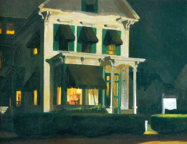
I just found a site that might interest you... The author contends that the house from the movie Pyscho was inspired by the painting "House by the railroad". What a hoot.
Thanks all! Yes, I've seen references to the Psycho House too. Depending on how I want to color it, it could be that too.
I received the totally 3D printed turret top last night when the Military Modelers Club of Louisville had a tour of the University of Louisvile's AMIST (Advanced Manufacturing Institute for Science and Technology). Ed Tackett, one of our members, is the AMIST director. It was an enlightening and exciting place to visit. There are two parts to it: the 3D printing lab and the 1st Build Makers space. That too is divided into two spaces: a large room for fabricating systems and then an elaborate, fully equipped manufacturing space with just about anything you could imagine including a 5,000 watt cutting laser that can cut stainless steel sheet.
The first two are the Makers space,
This is the manufacturing space.
Here's a picture of one of their two laser sintering 3D metal printing machines. This one's worth a cool $1.5mm. It can produce 3D metal parts with high accuracy from almost any alloy including aerospace metals such as Inconel. The manufacturing space has three full-time employees that will help you do stuff. I'm angling to get some consulting work with Ed since this stuff is right in my sweet spot.
Now here's the good part. Now that I have been registered in their program, I have access to the entire place for $2.00 each time you access the facility. There are individual (and modest) charges for the materials you consume. For the laser cutters, it's $2.00 per piece of raw stock you cut. In other words, it's like heaven on earth.
Here's the background. GE appliance's HQ is in Louisville. They were finding it impossible to design and manufacture small appliances due to economies of scale. They funded this facility to help them design and build small lot sizes. The facility is quasi-public. It receives no direct funding from UofL. It pays its own way. In the 3D lab they're doing a lot of DOD special projects. Major manufacturers like GM and Johnson & Johnson are having special projects done here. But, since it is affiliated (albeit at arm's length) with the university, it was a requirement that the public have access to the facility. I'm going to take advantage of it. Ed Tackett is a terrific resource and has vast experience in the entire world of 3D printing.
Here's the Cupola. It had a ton of very strange in-fill supports that I had to remove. Now.. this was done on a FDM (filament deposition Machine) and has some fairly obvious layers. I'm not worried about it. The roof part will be shingled. And I may or may not add some surfacer to the window frames depending on how noticeable the lines are. It's not the level of fineness that I get on the resin printer. Ed's resin printers are the same size as mine so it didn't fit on his either. In fact, he has an Elegoo Mars printer along with an Anycubic machine. Regardless, it would have a been a bear to scratch-build.
Speaking of printers, mine is driving me nuts. I'm attempting to print a completely good EMD 567 for a client. Out of five parts on the print last night, one was successful. Cleaned all the stuck resin and gave it another shot on 1/2 of the engine block. This time there was no "popping" as the platen was lifting. That's normally good news. Instead, when I paused it to examine, I found that NOTHING IS ATTACHED TO THE PLATEN. "Failure to launch". Total failure! The raft was firmly stuck to the FEP. Again, I changed the FEP film, this time putting on another piece of OEM Elegoo film. I was very careful in the installation. Started the print, no popping. Again, it was so quiet because nothing was stuck to the platen. I've just ordered some Epax, non-FEP film which is purportedly better to release the resin. Right now I'm ready to try anything. Ed mentioned that some of the films have a protective layer that needs to be peeled off. I thought maybe I forgot to do this. But there was no protective film on either the McMaster-Carr bulk FEP film I bought or the OEM film. I don't know what's happened. I was doing good work for months and then trouble came and hasn't left.
Attachments
That is certainly a great opportunity for you at the AMIST. The cupola looks great! Yes, that would be a bear to scratchbuild with traditional methods.
The Nighthawks looks great, Myles. I like the whole building. Really looking forward to seeing the finished House by the Railroad.
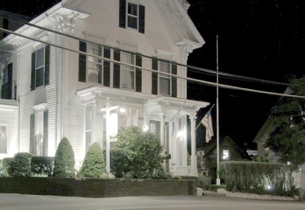
Here's another great Hopper house for you: Rooms for Tourists. The original is in Provincetown.
Attachments
Well Myles, that lab is a great opportunity. I guess the printer is like the little girl the curl. When it's good it's very very good. When it's bad it's horrid.
Miles, I have made it up to page 21 in your thread!! ( around 2015-16) I think more than 10 pages were devoted to your spectacular substation alone. Your attention to detail in modeling is matched only by your detailed descriptions and log.
I was sorry to hear your article on the substation wasn't published in O Scale mag, but I certainly understand their policy. Have you had anything published since then? I wouldn't sweat it, plenty of people have seen your work here.
Since your thread is so long and people, including myself, may be more interested in one project rather than another, have you thought of breaking out individual projects into their own how-to threads? Maybe editing out comments and redundancies? Or perhaps making an index? BTW, some of the old photos have gone missing.
You are an O scaler, really, with a three rail layout. You could have a lot of fun doing clinics and bringing your buildings to O scale conventions and meets.
I'd love to do Early Sunday Morning, but don't have the room for it.
Thanks to all who follow so faithfully!
Page 21 eh? If you read further you'll see encouragement by my readers to offer the article to Railroad Model Craftsman. They accepted and published an 8-page article in 2015. Then they accepted and published a three-part article on building the Bernheim Distillery in the Oct, Nov and Dec issues of 2018. Now they have an article about constructing the humungous engine house. I don't have a pub date for that yet. Then I sent two articles to our own Allan Miller of OGRR Magazine and he has shown interest, although nothing more yet. Stay tuned. You definitely need to keep reading.
I have a local fellow who's trying to talk me into running a series of Master Modeling classes. I'm torn. I really like retirement and not having serious commitments. I am lobbying though, to do some consulting/mentoring/teaching at the AMIST center. It's local and wouldn't require traveling. I have done a soldering clinic at our local model building club which was fun. As to creating a more organized approach than this meandering thread, I look at the magazine articles to fill that void. I could be persuaded to go further. One possibility would be to create my own web site, but then you're no longer a model builder. You're now a web producer. Same goes from making videos. I'm not sure I want that, as there are a zillion already out there. In fact, I just finished a 10-part series from Ted at eHobbies where he built the Typhoon I'm working on. I did learn some stuff. I'm always learning!
Speaking of Typhoons. Here's the latest shot of my progress. The engine build borders on insane. All the top engine appliances are in place. Next up is putting all the stuff on the bottom. I'm building the plane with all the skin off the front so all of this will be visible. I haven't weathered any of this yet. I don't weather heavily. I like things in well maintained, near-factory-fresh condition. All of the framing in the wings and around the cockpit will not be visible in the finished model.
The new Epax vat film is arriving on Amazon Prime tomorrow (Sunday) so I'll have it on the machine on Monday and see if it solves the sticking problem. I really need the machine working. I've got a lot of stuff to go on it.
Attachments
I noticed your mention of purchasing the chop saw for wood work and I add my recommendation that it makes fast work of building stick by stick type buildings. You can set it up just like a full size chop saw building framing.
Your model work is fantastic and inspires me to spend more time with my 3d printer to super detail structures. Thanks for sharing all your work, it is truly inspiring.
You're very welcome. '
Boy! Don't post for a week and you're relegated to page 2...
I was having a war with my 3D printer. Nothing was sticking to the build plate. I was changing teflon film way too often and it gets expensive. I sanded the build plate to give it more tooth. Nothing was giving any sustainable improvement. Finally, I started pre-coating the build plate with a thin (brushed on) application of UV resin and pre-curing it for about 20 seconds in the UV Curing box. This gave the resin something to hold onto, and it worked! I've had a couple of minor failures, but they were support related, not due to immediate loss of adhesion.
I've now printed two of eight of the Mansard windows for the House by the RR. These would have been bears to scratch build.
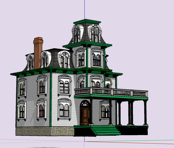
I've done some final modifications to the House drawing. I had forgotten to add the cornice at the 2nd/3rd floor break of the tower and added full interior walls and stairs. The model begs to have and interior, but I'm not sure where it's going to end up and if it will be visible. I'm in the process of doing the laser cut drawings, but I had to stop since I was still making changes to the structure. I think it lined out now and I'll finish the cutting plans.
I finally finished Bernie Winkler's EMD engines. The complete engine took me three weeks due to the troubleshooting. This is the unspoken side of 3D resin printing. And last night I printed the porch columns. Funny… (not haha, but peculiar). I set it up to print three with the exact same setup. I know they're exactly the same because there is a "Clone" feature on the slicer so you can copy the part and all the supports. I had two outside columns facing one way and a center one the other. The middle one printed perfectly. The two outside one failed. Only this time while the failure to hold onto the supports happened early, they started printing halfway through the job so the part that was last to come out of the vat was printed correctly. Weird. I'm going to redesign the supports to give it more hold early on. But the rafts held like crazy to the build plate.
All the Northeastern Strip Wood arrived for the Tie Hacker's Cabin Project. So… there will be two railroad projects working more or less together: House BTRR and the Rusty Stumps project. So stay tuned.
Meanwhile, progress continues on the Typhoon. Ran into a problem fitting on the belly pan. Had to do some surgery on it. It's starting to look like a plane now. Got the exhaust stacks in and weathered.
Notice how far forward the main wing sits. The Napier Saber engine was a beast! 24 cylinders in two flat sixes with two crankshafts stacked one on top of the other. 2400 hp in the basic form and weighed about 2,400 pounds and then you had the radiator and coolant and you have a center of lift that pushed way forward. Water cooled engines especially with sleeve valves like this one were heavy.
The early Typhoons had the unfortunate problem of the tail falling off. They solved that problem on the early ones (like this one) with a series of reinforcement plates surrounds the tail area and you can see in this image showing my filling and mods to fit the belly pan. To fit the belly pan I had to cut a 1/16th off of the back edge and modify the fillet area too. It was annoying and I don't know how the error occurred. The entire wing assembly ended up being 1/16" further aft than it should have been. And yet, there was no way to mount it any differently, or at least I didn't know any.
Attachments
Great job on the engine, Myles. Glad you solved the printing problem.
The airplane certainly does look complex. Great job!
Trainman2001 posted:I was having a war with my 3D printer. Nothing was sticking to the build plate. I was changing teflon film way too often and it gets expensive. I sanded the build plate to give it more tooth. Nothing was giving any sustainable improvement. Finally, I started pre-coating the build plate with a thin (brushed on) application of UV resin and pre-curing it for about 20 seconds in the UV Curing box. This gave the resin something to hold onto, and it worked!
I started having the exact same symptom--build-plate non-adhesion all of a sudden after months of proper operation. I solved the problem by greatly cranking-up the "Bottom Exposure Time" parameter in Chitubox. I set it to 60 seconds. This causes the initial layers (usually the raft) to really cook onto the plate. Since it only affects a few layers, it doesn't make a significant impact on the build time.
There are a million parameters in play here, so I don't know if this will work for you, but it is worth a try. If it works, it is easier than painting the plate for every build.
Thanks Pete. I did raise the bottom time a bit, but probably not enough. Meanwhile, I'll keep pre-coating. It takes about five extra minutes since I have to use a razor blade scraper to get it off. I'm going to do some more investigation and look at that z calibration too.
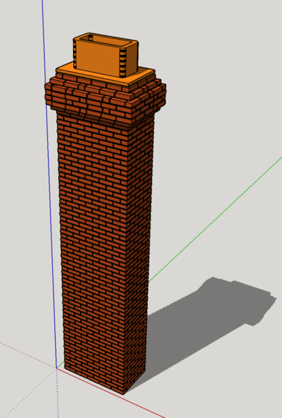
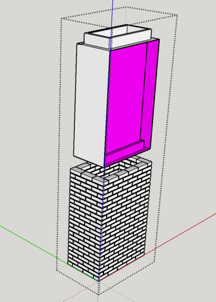
Decided to try and do something particularly finicky. Instead of getting the large chimneys laser cut, or worse, hand lay a zillion little styrene bricks, I drew the chimney with individual bricks on SketchUp leaving space for the "mortar", and then set it up to be entirely 3D printed. I set it up with two support schemes: heavy and medium supports. And this will be an interesting experiment since I rate this as one of the more challenging 3D objects. Didn't take as long as you think to draw because you can copy a regular series of objects. Once I copied one brick over another with the mortar spacing of 3/8" (it's all drawn in 1:1), you simply say, for example: "X35, and it will reproduced the stack with all those bricks at that spacing. Actually I reproduced them with one blank space between so the intervening layers would be properly offset. The hardest challenge was fixing the inner box that sets the bottom of the mortar space and contains the flue tile at the top.
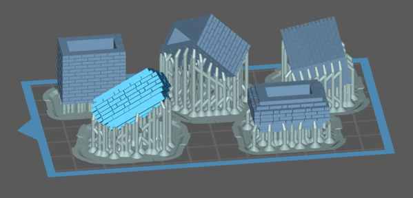
I didn't set it up erect as you see in the image, but rotated in slightly in X and Z axis to minimize the footprint (and suction on the teflon film). This has an unintended effect of causing the leading bottom corner of the bricks on the lowest size to start forming unattached to the brick body due to the mortar groove. This would be an island and would fail to print. I made sure there were a ton of supports contacting that specific point to hold it while it formed and then attached itself to the main brick body. Some of them will not print since I don't believe every brick course has been supported that way. It should still print something. I'm interested to find out which support system is the best which is why I chose to do it both ways.
I printed one successful porch column and have two more on the Machine that will finish later tonight. I revised the supports on that job to see if I can correct what failed yesterday. Since I changed he building so much, my print files for the trim (corbels and cornices) and the balustrade rail are no longer correct and I'll have to re-slice them.
Attachments
The printer is cranking out stuff. I tried printing the Chimney with two different support schemes: heavy on one and medium on the other, I came to the quick conclusion that heavies work great and mediums really didn't work much of all. I had messed with my medium support settings and they were really like "light" ones. Regardless, they all failed about 1/3 into the print. The heavies finished one heck of a chimney.
Here was the chimney as it came out of the printer. Here was the first side.
And here was the other. The amount of supports directly on the bricks, I knew was going to create some problems. Notice I made it mostly hollow to save resin.
After cutting off the supports I was left with a mess. Again… all predictable. This is resin printing's major drawback. If the object has four good sides, one or more is going to be dealing with the support remnants.
However, after sanding and filing, I did make it presentable. I re-sawed the horizontal mortar lines, but the vertical lines are a lot cause if they were involved in the supports. The good sides, though, are really good. I put the chimneys in place so the not-so-good sides are facing inwards.
Good Side: Looks like a chimney to me...
Even the bad side is reasonable.
So… the question is, "Is this a more effective way to produce a good looking brick chimney?" Pros: even with an hour of cleanup you get a fully assembled model with lots of detail. It certainly is more efficient that the brick-by-brick styrene ones I've built. A chimney of this size in that method would take a week. Laser cut goes together faster, but you're left with end grain at the corners that needs to be hand-scribed to look reasonable. In this case, I "laid" the bricks correctly so the corners have brick ends on every other course as is prototypical. I have another one ready to print. This time I altered the angle on the build plate so the supports come in at a higher angle making them easier to remove. I can make them shorter by just cutting off the amount I don't need.
I finished two more pillars. One has a little warp in it. I needed a way to sand the lower base perpendicular to the pillar pole. I needed to pack it out by about 0.055" so it was the same as the distance from the sander's fence as the upper and large plinth. This worked out pretty well and they will stand more or less vertically.
I made the packing with some laminated styrene strips. The divots on the pole below were repaired with Bondic and then re-sanded. I was able to reshape the portions of the upper details after removing the supports. The most challenging skill with 3D resin printing is clean up.
I printed two smaller exterior doors. They printed perfectly. I broke one of the delicate window mullions when cutting the supports. If I can't replace it with a styrene piece, I will reprint it again. Here's the good side. Shows all the necessary details including nice knob and lock.
Here's the support side. I probably could plan the supports better so they wouldn't fall directly on the paneling seams. If I kept them off of those details, sanding wouldn't destroy the effect.
This will be on the inside of the building and totally unviewable. They'll cleanup nice enough. I think I will reprint since I also cracked the one with the broken window frame to try and remove the small warp that had occurred after hardening. I was concerned about the scale of these doors, but after checking them with some left over Tichy Group doors, the match exactly. I sized them for 3 feet wide and a tad under 7 feet tall since you do all SU drawings in 1:1 scale. Then I shrink by a factor of 0.021 which gives pretty good 1:48. The number is actually .0208 so I round it up.
Right now I have another chimney on the Machine. It will be ready tomorrow morning. I'm using a different angularity with the heavy supports. I'm almost finished the 2D laser drawings. I had to do some final adjustments to the SU version before getting the cutting drawings done. I'm seriously thinking of taking advantage of the U of L 1st Build Center and doing the laser cutting myself. They have the MDF, but I'll provide my own Basswood clapboard siding. Northeastern Scale Lumber comes in 6" widths so I sized the wall heights to us exactly that size to avoid any horizontal splices.
Attachments
It is interesting seeing how each type printed part has different support and cleanup issues. The chimney is definitely sharp looking as are the other parts
Nice job on the printing. Even the bad side of the chimney looks good. The small pieces of missing brick look real for an old chimney. Would putting the piece i n some sort of a clamp when it's drying help prevent warping?
Love the chimney. It is so great to be able to produce one-off architectural details as needed, rather than having to use "me-too" products that are just "close enough".
If you don't mind me kibitzing one more time: What do you think about attempting to print the chimney perpendicular to the build plate and without supports? I am pretty sure that the brick section will print just fine. You MIGHT have to print the crown separately, but I bet even that may print. You would probably still need a raft, though.
Thought about it… If you do a mind experiment and build the chimney in you head, you'll notice that as the next layer forms outside of the mortar depth, that edge will be one layer thick and sticking out of the edge. It may not be able to be pulled off the film without tearing away. I'd like to make a little, short test piece to see if it works. The main problem with flat layouts is the suction surface compared to the number of supports. I don't do many flat layouts for that reason. But, I'm open to try.
I did a test drawing separating all of the parts. I'm going to run the following test to see what happens. I set up the plain brick column in three orientations including flat, and then did the decorative top in two orientations, also with one flat. It's not too high so it shouldn't take too long to run. I'll let y'all know how it works out.
Attachments
Trainman2001 posted:Thought about it… If you do a mind experiment and build the chimney in you head, you'll notice that as the next layer forms outside of the mortar depth, that edge will be one layer thick and sticking out of the edge. It may not be able to be pulled off the film without tearing away. I'd like to make a little, short test piece to see if it works. The main problem with flat layouts is the suction surface compared to the number of supports. I don't do many flat layouts for that reason. But, I'm open to try.
Hmm. You may be right, But I think it is worth a shot. The situation you describe occurs any time you introduce a flat surface of any kind parallel to the build plate, and I am pretty sure I have done that successfully as long as the overhang isn't too big. Who knows, though? Lots of black magic here. I guess you could avoid the issue by canting the "mortar" a tiny bit so that each layer supports the next. This kind of thing must be why professional model makers make the big bucks.
Pete, the test was a success! The vertical parts, both the main body and fancy cap, printed perfectly and I'm going to revise my design and print them again with the new scheme. I'm going to print then in a couple of sections so a) they won't weigh so much and not strain the attachment, and b) reduce printing time since it's directly proportional to how tall the part is.
I did the five pieces. All printed without failure, but it's clear that the vertical set up produced parts that which would clean up in moments rather than minutes.
From now on I'll be printing my chimneys instead of laser or hand-building them. Thanks for the idea.
I cleaned up the one good door and it will work fine. When painted and glazed it will look as good as a Grandt Line commercial product.
I did clean up the second chimney done by the first method, so regardless of my next steps, I'll have two of them. Now that I know that I can make some with bricks going all the way around, I am compelled to redo them.
I'm printing another main window. The first one, while a great print, got some of the little details damaged on the doodads that hang below. I want a perfect one to be able to resin cast them. It's still gratifying that every print I'm making is sticking like crazy to the build plate with the pre-coating. At least I got that solved.
Attachments
Looking good Miles. Can't wait to see the house come together.
Awesome! Thanks for taking the time to do the test. Now we all know!![]() We've all had this "diagonal printing" thing drilled into our heads--it is easy to forget that it isn't always the best approach.
We've all had this "diagonal printing" thing drilled into our heads--it is easy to forget that it isn't always the best approach.
BTW: Don't be afraid to print directly on the build plate when appropriate. You do tend to get a little bit of vertical distortion in the early layers, but for many designs it doesn't matter. It is especially handy when you need a perfectly flat surface. If you don't mind not having a doorknob on the inside, I bet you could print that door flat on the plate. Talk about a fast run!
The test was almost perfect. The not-so-perfect part was a drawing failure in the middle-sized chimney piece. I printed two full sets of these modular chimney parts. Only the middle-sized piece failed. Therefore; it wasn't a machine failure, but had to be the drawing. Something was definitely weird!
The part consists of two drawings. And inner rectangular box served three purposes: a solid surface for the bricks, extend outward into the mortar space to act as mortar in the finished object, and provide the upper and lower engagement pieces to build the entire chimney. When I pulled the inner sleeve out, I found that somehow I had removed faces. Actually two, but in my re-creation I'm only showing one. Without those faces, half of the inner box was unprintable. With the inner box, the bricks had no surface on which to form and it created the failure.
The bricks, as I drew them, are all separated by a scale 3/8" mortar gap and none would print except the first course.
So that solved that problem. Meanwhile, the failure messed up the FEP surface and it was time to replace it. I decided to go back to the Elegoo OEM film. I was told that some films have protective layers that need to be removed. I hadn't seen any, but was having bad luck with Elegoo film. So I looked a bit harder. DOH! There it was, two layers of protective film covering the teflon. So all that time, I was trying to get a non-stick surface on whatever polymer used to make the protective film.
I changed the film on Friday and was all excited that I had solved my adhesion problem. I started it to print another Mansard Window and when I went down on Saturday morning and there it was. A totally empty build plate! Another failure. I didn't use the pre-coating technique on this print.
I cleaned off the FEP without damaging it and this time ran it again with the pre-coat and got a perfect print. And I've printed three more times since then without failure, but using pre-coat each time. I also went back to the factory resin settings (8 seconds and 60 for raft). I then reprint the middle pieces and more top brick work. This time I inverted them so the female part was facing up (without supports) since I found that cleaning supports was easier on the male part instead of the internal cavity.
Those new parts are in the curing box. I'll assemble them tomorrow and take some images then.
The latest Mansard window has a small modification: I added another reinforcing strut on the bottom to correct some flaring of that part. I had hollowed this object to save resin. In this picture you can make out the flaring and how it was corrected with the design change.
I also used sticky wax to fasten down all the furnishings in the machine shop. I'm getting ready to call that project done, get the good pics taken and get the article printed.
I opened the box of the Tie Hackers Cottage in anticipation of starting it. The Typhoon is masked and waiting for some mild weather to spray the Tamiya primer outside.
Right now I'm printing a couple more porch pillars. I'll have two more left after these. It will take several weeks of printing to create all the architectural details I need to build the House by the RR. Speaking of RR, I actually ran some trains today! Everything worked nicely.
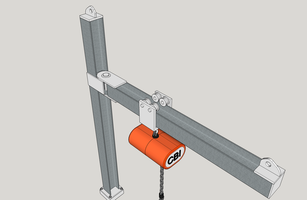
I'm preparing to scratch-build a couple of chain hoists for the engine house, so that will determine when it's actually done. I'm going to 3D print the hoist trolley.
Attachments
The porch pillars were successful and I only need two more. I then wanted to print a set of corbels. I loaded the slicer with 15 sets. Each set consists of two corbels with a common back piece. I got this many successful ones. The details are impressive. These sets will be glue to a fascia board. Instead of printing with the board attached, and thereby making it a much more complex process since their spacing would vary depending on wall width, this way, I'll just cut the fascia boards to the right length and glue on separate corbel sets. The image is before post curing and final finishing.
The rest failed. I used medium supports and they didn't hold up. I had a bunch of crap on the FEP and did some damage when removing all of it. I changed FEPs back to the last EPAX non-FEP film that I had. I think that stuff works better than the Elegoo OEM film. I was hearing that Elegoo film "popping" over the last prints I did. All the other ones the popping (which is the sound the film is making when the cured resin is still sticking to the FEP and releases suddenly when the plate pulls it up. In this case, the sticking was too much for the supports and they failed. What didn't fair was the rafts. All of them were on the build plate due to my pre-coating technique.
I finished up the multi-part chimneys. After a lot of precise cleanup, I glued the pieces together with medium CA.
Here are the multi-part chimneys compared to the one-piece units. The bricks are significantly better, although there are discontinuities at the junctions. It will be okay when painted and mortar lines filled. I will never have to make such a chimney again, but if I did, I would reduce the number of segments. I could make the individual pieces taller, but just not as tall as the entire chimney.
I also spend some time fussing with removing the axles and traction motors out of the old Blomberg and Flexicoil trucks I had made months ago, Neither print was worth anything other than a proof of concept, so hacking them up didn't bother me too much. I used the Dremel with a 1/16" carbide router to remove them just as if they were an actual truck by excising the axle box from the side frames and removing any areas of adhesion between the traction motor and the truck frame. I photograph this tomorrow. I also made separate drawings of traction motor/axle/wheel sets which I can also print.
Attachments
I think the multipart chimneys look great!
Decided to get a bit "Frisky" with the printer. Instead of printing the corbels with supports, I set them up to print directly on the build plate. No raft, not supports, no nuth'n. And it worked perfectly. I was told that for small stuff you can do this sometimes. This was one of those times.
They were stuck very tightly so I used a razor blade to peel them off. I was a little to aggressive and lost four of them. I reprinted the next batch the same way, but was a bit more gentle and didn't lose a single one. Without supports there was almost zero cleanup required; just a light sanding on the edges and faces. They're really beautiful. From the SketchUp 3D Warehouse I downloaded a single corbel, but I needed them in pairs. I added a flat base to hold them together and make installation on the fascia strip which will be cut to specific lengths for the different walls. I now have enough to do the entire building.
I printed a double set of main windows to speed up the process of printing a building's worth. My support scheme here was daunting and I broke the horizontal mullions on both windows when clipping off a ton of supports. I'm going to revisit this and set it up differently. When I was printing the first version I had the bottom doodads on top, and it was hard to remove the supports without hurting them. With this inverted position, that problem went away, but a new one was created. The supports were in the curved decoration at the top and more on the those delicate mullions. I try again. But, on the bright side, they printed perfectly with no popping. The EPAX Non-FEP film is much better than the Elegoo OEM FEP. I just ordered some more.
I am bummed that we're heading for a crisis of biblical proportions. We are surely going to a recession and if things don't go right we could be in a depression. Our country is getting sick and we are no where near the apex of this curve.
These are serious times my friends. I hope all of you take care of yourselves, loved ones and neighbors. As a model builder I, at least, can stay in the house for days on end without losing my marbles. Can't say that for my spouse. I'm a half-full-glass kind of person.
Attachments
The corbels look great, Myles. 3D printing allows for detailed models that were not available to most modelers. Only the most skilled modelers could add that kind of detail. Stay healthy everyone.
Yes and no. While it has the potential to do what you said, the actual execution can be quite challenging. My chain hoist project for the engine house is a prime example. I drew it all up on SketchUp and it printed as a single unit including the trolley, hoist, chain and hook. But the act of removing the supports rendered the chain and the connection links between the trolley and hoist useless. I'm in the process of making metal connections and I have to buy some real chain since I don't have any. I will be adding a metal rod and turnbuckle between those eye plates.
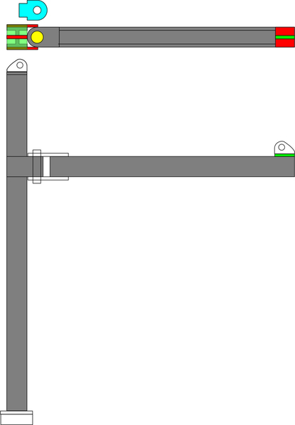
Here's the drawing of the hoist framing. It's all Plastruct 5/16 H-beam left over from the refinery project.
I printed two of them since I think I want two hoists supporting the room. You can see one broken off chain. The "intact" one actually has a Bondic repair since it broke off too. I abandoned using the chain entirely since it wasn't gluing together in alignment.
The trolley fits on the Plastruct H-beam well. It really should since I measured the beam to make the trolleys drawing.
I replaced the resin connection between the trolley and hoist using 0.032" phos-bronze wire. I will make another ring to tie the chain to the hoist underneath. Took a bit of work with the Dremel, MicroMark power sander and needle files to clean up the support debris from the hoist. Looks worse in raw form. Painting will make it look better.
The front door printed perfectly, but again, I had to do some repairs on the small demi-lune window mullions that kept fracturing when attempting to cut the supports. The Bondic works wonderfully to put these parts back together since they're the same material so it's really like welding.
It will work. I had to arrange the door frame in that orientation so I didn't get any supports on the beautiful front. No one will be able to view the rear… ever. The door didn't warp, which is good. Bad was I lost the outer door knob and will have to make another knob out of brass.
Attachments
" also spend some time fussing with removing the axles and traction motors out of the old Blomberg and Flexicoil trucks I had made months ago, Neither print was worth anything other than a proof of concept, so hacking them up didn't bother me too much. I used the Dremel with a 1/16" carbide router to remove them just as if they were an actual truck by excising the axle box from the side frames and removing any areas of adhesion between the traction motor and the truck frame. I photograph this tomorrow. I also made separate drawings of traction motor/axle/wheel sets which I can also print."
So where are they? I'm looking.....![]()
I had to ask. I love to follow your work and see what's new.... and old. You must have a ton of patience to follow thru with all the learning curve. I would have exited the building.
They are here…
The Blomberg wheels weren't too bad, but the Flexicoil wheels weren't so hot. I filed and filled them and made them respectable (at a distance). The wheels are painted Tamiya Dark Iron and then brushed with Dr. Brown's red rust pastels. Traction motors were painted semi-gloss black and then given a rub with Bragdon's earth/dust weathering powders.
I finished the two hoists bodies. I scraped all the printed details and substituted metal. The hoists were hanging off balance and it bugged me so I drilled them and added solder weights until they hung reasonably level. I needed chain.
I have an old plank on frame ship model un-built that's been on the shelf for, would you believe, 43 years. The kit is the Royal Sovereign. I've cannibalized a few parts from it over the years and thought it might have some chain. It did. It's a massive kit, with not-so-hot planking material, parts that are just printed on a sheet of not-so-hot (and now very old) ply which you have to cut out yourself, a keel that's slightly warped, and literally thousands of cast metallic details. But the real reason I haven't built it is it has basically no instructions, just 6 large sheets of plans. It would be an absolute bear to construct, especially since there are marvelous laser-cut kits like this on the market. So I opened it up and just for fun stuck all of the frames into the keel. It's almost 1 meter long. I am never going to built this kit! If I haven't built it in 43 years, odds are I never will build it. Besides, if I did I would have no place to put it since it's gigantic.
Ironically, I now have a shop with enough wood working equipment that I could actually build i
My printer has been working very well (knock on wood…) and now I'm really working on placing objects in such a way as to make them easier to clean up. Here's a bad example. I printed three single windows yesterday. Here's what it looked like before cleanup. In the act of using the Dremel with a needle pointed diamond burr, I actually cut through the part itself, thereby killing it. The supports on the internal edges are the hardest to remove. The missing drop on the left bottom was sacrificed for one of its brothers. This window went into the trash.
On another the curved window top broke out, so I put a piece of styrene for backing and filled it with Bondic.
After filling, sanding and filing here were the two windows that the House needs. The arrows point out Bondic filled areas. I also had damaged the drop on the right hand window. I used the one I cut from the scrap window and glued it on with Bondic. It's always good to print more than you need. Regardless of the number of pieces on the build plate, the print time is the same. The variable is the height of the object, i.e., how many layers. It also uses a few cents worth of resin. A note about Bondic. Technically, you can't use it on blind joints where the UV won't penetrate. This is a special case. The resin, even though opaque in visible light, is almost transparent in UV so the light DOES penetrate the joint and harden the Bondic. I wondered how the UV can harden the entire object in the UV hardening box. I opened it and saw that the whole object is glowing with the light. The light passes through it.
I printed the first set of railings. It had WAY TOO MANY supports and I had to almost destroy the details to get them off. I spent an hour with the Dremel to do it. I re-set it up on the slicer and placed light supports ONLY to the specific points that would be islands. I printed it last night and it was successful. I'll clean it up today and expect much better results than what you see here.
I ran the main door, but after looking at the print found that the drawing was defective in several areas. I also redrew the double windows to make a version with the sashes open, and fix a flaw that kept appearing: the middle horizontal sash frame kept breaking at the edge junction. It turns out that it wasn't actually connected. There was a minuscule gap between it and the side frame. The printer prints exactly what is on the drawing. If there's a gap, even if you may not see it, it will produce a weakness at that point. I also found out why the door knob fell off during cleaning. The drawing was downloaded from the SketchUp 3D Warehouse. The artist drew the lock mechanism in 1:1 detail. It had all the internals, rods, screws, etc. It also had the front and back formed covers made as they would be… hollow with scale thinness to the walls representing the sheet metal it would be spun from. These hollow parts did not print. So the knob formed, but nothing was behind it securing it to the door. I found this out when watching the part grow in the slicer animation. When it reached the door lock part, there was just thin lines and voids being formed. I knew immediately that this was why the lock assembly was falling off. There was also the panel detail on the side light that wasn't forming on the right side. It too was a drawing failure. It's ALMOST ALWAYS A DRAWING FAILURE. I'm on the lower part of the learning curve.
I showed this image yesterday, but there's more information about it.
I re-sliced the door so it wouldn't have that forrest of supports which, as you can expect, was awful to remove. I set it up almost vertically with a rotation edge-wise, but didn't tilt to to the flat side to reduce the supports needed. Objects can self-support depending on their orientation. I also limited the supports under the demi-lune window. There too were some structural errors in the drawing.
So… Pat, to reiterate my response to your post the other day; yes, 3D printing makes it possible to do modeling that only experts would do in the past, but opens up a whole other world of expertise that you need to master. It's a trade off.
Attachments
Sorry about not posting yesterday's work yesterday. Just posted it and now I have to give you today's.
I ran the upgraded railing and it worked much better, although not perfect. Two improvements were needed with I've added to the drawing/slicing to really zero this thing. First, I hadn't caught all the fat supports to change to thin ones which made for some more over-careful cleanup. The second was that part of the corner post that wasn't getting any fill. I went back and checked the drawing and couldn't find out what was going on. I thought I corrected it, but found I was looking at the bottom of the post, not the top. After slicing it again I watched the post form and found that the top curved-edge surface was showing up as a hollow with a thin skin with no thickness. Surfaces without thickness don't exist and therefore don't print. On the work today, I filled the gaps with Bondic and sanded it flat. I fixed the drawing and re-sliced and will print more tomorrow. Meanwhile, here's the much improved railing. These I can use without reservation. Tomorrow's print will even be better. Allows show the filled areas.
By setting up the railing at a pretty steep angle, most of the horizontal members were self-supporting. There are just two areas on the balusters that need a support.
The weather today was very nice and I primed the hoists outside with Tamiya Flat Gray Primer. Tomorrow I'll put on some color coats.
Attachments
Myles, The pictures did not post on the first of your two posts.
Darn, they all timed out. I did the whole post and forgot to hit send. I'll reload them.
Adding the pictures after the fact makes sort of a mess. 1,000 pardons...
No need to worry! I've done the same thing. Those last two railings really look great!!
The pictures printed ok. I love the details on the parts. The railings look fantastic. I understand your comment on complexity trade off.
A picture's worth a 1,000 words. Here's the front door with the new setup. You can immediately see that both the number of supports AND where they're connected is significantly better than my first attempt. There are very few in the delicate demilune window area, and those that are much smaller. The door knobs did form, but their shafts were too fragile and they left. I will go back to plan B to make them out of brass.
Compare the above to the first attempt. By having the positioning very vertical I was able to limit the supports since the piece self-supports as it grows. I also fixed the missing panel. In the slicer, when you view the object from the underside, shows in bright red areas that will be unsupported. You need to put supports there. Also, you can move the layers up and down and see where the contour lines come together in an unsupported point. That point would be an island and fail. I also have another piece of software that evaluates the sliced object, layer by layer, and points out explicitly where an island will form and identifies the layer number. You go back in the slicer, dial it to the that layer and watch the island form by cycling forward on the layer slider. You can then put or maneuver support to those spots so the print will be successful. It's very detailed oriented and takes a lot of patience.
As a result, here's the finished product. I even got the door's hinge bar formed correctly and glued it to the frame with Bondic. When gluing resin to resin, Bondic is the best since it's the same material so you're effectively welding them together. It will be fun to have a building with the door open, welcoming visitors in.
I'm running another triple set of railings. This will be the final iteration. I've perfected the setup and fixed all the drawing errors. Again, the setup is very tall and vertical so it self-supports. This way I was able to almost have no big supports in the baluster area. Because of the verticality, it's taking 10 hours to print. Remember, it's not how much surface area on the build plate that determines print time. It's number of layers = height, plus individual layer height and layer exposure. If I printed in 10 microns and 10 seconds a layer it would take 16 hours to print. This print will be done at 10:30 tonight. I'm not going to run anything more during the weekend. I'll need one more run to get the total railings I need for the building. I then go back and finish printing Mansard windows (need 5 more) and main windows (need a ton more).
Everyone have a nice, quiet, socially distant, weekend.
Attachments
The door looks great. You're really mastering the 3D printing.


