Coming along nicely, Myles. Clever way to trace the stairs. I'll have to remember that. 👍
Thanks Pat!
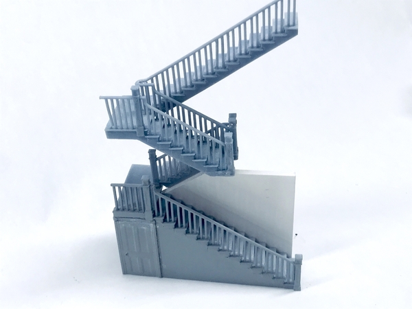
The attic railing prints came out perfectly. I post-cured them, but didn't trim them yet. I'm thinking that having them cured will impart some more strength to the part when I'm removing the supports. The final set of steps is on the machine now and will be ready later tonight. It's the weekend and my house rules are in effect, "no building on the weekend."
Cabin: I airbrushed the corrugated roofing material my "galvanized steel mixture (Tamiya Flat Aluminum and Flat Black). When it was dry I measured and cut the pieces into 19 scale feet long and 4 scale feet wide. The pieces go right over the peak.
I'm using a new adhesive on this project. MicroMark SM Transfer Adhesive Tape. This is some weird stuff but has definite value once you figure out how to handle it. It's VERY STICKY!!. There is a non-stick wrapper that you need to keep handy since when you unroll it the sticky side is facing outwards and the roll will stick to or pick anything is touches. You take the tape with the back and apply it to the part in question and then remove the backing leaving behind a very sticky contact cement surface.
I thought that it would be a perfect application to apply the tape to the purlins and then stick the roofing to it. The adhesive is strong and holds like crazy. It took me a bit of trial and error to keep it from sticking to everything else.
The tape is 3/4" wide and it's kind of hard to cut it to shape before applying. I applied it to the purlins and then, with a brand-new #11 blade, sliced the excess away from the purlins. Here was the result with the backing paper still attached.
After removing the backing I was left with an adhesive layer attached to the purlins.
It's REALLY STICKY. Have I said that enough! Every time I reached for the building I kept grabbing it near the purlins and the *%@)** building stuck to me.
After spraying the galvanized, I had to "rust" it. I used some 99% IPA with added black India ink to wash away the galvanized and reveal the rust underneath. I then added some more color with brown and red brown pastel chalks. I blended the pastels with a Q-tip. I had to be careful to not rub the surface too hard or I exposed the bright metal underneath. The Tamiya paint is IPA soluble, the Rust-oleum primer is not, so as long as you don't rub too hard, the rust is revealed nicely.
The roofing piece were 19 scale feet and I measured 9.5 scale feet and bent the piece 90 degrees to apply it to the building. The adhesive worked perfectly and holds the roofing like crazy. After finishing the lower layer, I measured and cut pieces 6 scale feet, also bent in the middle to form a peak like the big sheets. For these pieces I applied the adhesive to the roofing itself. It was simplified because the roofing was the same width as the tape. I put the tape on each leg of the piece (3/4") and then used scissors to cut off the excess. You can cut this tape with scissors, but the tape excess will stick to them. I had to quit before finishing the upper layer. Will finish on Monday.
I'm going to go back and paint some judicious raw sienna (or is it burnt sienna— the darker one) to further emphasize the serious rusted areas. I really like my galvanize color… I still have to add some lighting, otherwise this whole deal will be in shadow and nothing will be seen. There's a ton of resin castings that need to be painted and added. I also have to prepare the chimney and the foundation. It's a nice model.
Speaking of models. We had our weekly Military Modelers Club of Louisville meeting on Go-to-Meeting online. It works pretty well and some folks are saying that's it's enabling them to attend meetings that previously they couldn't. We had a video presentation of the fabulous air craft models of Chuck Bowling. Whereas I'm a more eclectic modeler, Chuck specializes on 1:32 aircraft almost exclusively. His models are exceptional.
While it's fun to meet in person, having this technology available now is a G_d send. I remember working with ARCO Chemical when they installed their first satellite video conferencing systems to communicate between their far-flung operations. Each studio cost about $500k with Ikegami cameras and projection systems to give big images. They had a good 2 second delay so telling jokes was very awkward. Now we have the same capability with the phone in our pocket. With Apple FaceTime, there's often no time lag at all. Amazing! We shouldn't become complacent. This stuff is really cool.
Attachments
The shed looks great. I was thinking. Cureing the part to strengthen before removing the supports, also strengthens the supports making them harder to remove. Chicken/egg? Which is better?
Yes and no. If I was going to use the clippers or Xacto to remove them, then it is much better to do it uncured. When cured hardness and brittleness is increased. But I’m going to remove them abrasively so the hardness works in my favor. Abrasive cleaning doesn’t mechanically shock the part or incur any appreciable side thrust thereby keeping it from breaking.
BTW: the long stair reprint was successful and finished last night. It’s still on the Machine. So, unless I break something going forward, the long slog to print an entire staircase is finished. I’ve decided to assemble the entire stair with Its surrounding walls as a complete module which I will insert intact into the building. That way I can ensure that it’s all aligned.
Thank you for sharing Myles, I’m following along with the popcorn. I appreciate the explanations and your trials and tribulations. You show everything, warts and all, and I thank you for that.
Andy
Makes sense. Thanks Myles.
I'm a little late here with this comment, but what an ingenious mod for the chopper Myles! That's an article in and of itself.
Thanks. I did send a short description into Fine Scale Modeler for entry into their Tips and Tricks column. You get a quick $25 for them. I've had three over the years. It could make a short article too. I'll write it up and see where it goes.
Spent all day working on the printed stuff. Got the stair built, and fixed those fancy interior doors. The fork lift truck wheels are done and hanging on the machine. They printed well also.
I cleaned and assembled the attic railing system. I did have a couple of minor fractures, but Bondic fixed them up.
I cleaned up the wonderful print of the 1st stair flight. I then used Bondic to hold it to the railing system. All of these supports were removed abrasively. There wasn't a single flaw on this part.
After assembling the stairs I had to fix a weakness. The 1-2 flights are held to the 3-4 flights by just some Bondic at the bottom of the adjoining newel posts. That joint didn't hold up well at all. So I drilled and pinned it in two places. It won't come apart again and I can be secure in the knowledge that the alignment would be stable.
After assembling all the flights I measured and cut a piece of foam core to serve as the wall next to the first flight. Most if not all of the interior walls will be foam core only because it so easy to work with. I'm going to fully enclose the stairs in their respective walls and install it as a module.
I then decided to tackle those damaged interior doors. I conceived that i could separate the top rail of the door frame in SketchUp and just print that bullseyes included. Then I could cut off the misshapen parts and glue on the new one. I chose to print them directly on the build plate (no supports) and since they were so small they printed in 15 minutes. I produced 10 in one go.
I used the belt sander to remove most of the bad molding, and trued the edge with the precision sander. I glued the bullseyes back-to-back so there would now be bullseyes on both sides of the door, where there weren't as I originally printed them.
And here are the fixed doors excepted for the one with the door knob that appears to high. It's because I glued the new trim on the wrong end of the door DOH!! I will remove tomorrow and do it correctly. They're not perfect, but at least there are no divots caused by support removal.
I also printed some fancy baseboards. Some on supports others on plate directly. I'm going to see which comes out better, although considering how well the door trim came out I pretty much know which one I'm going to pick.
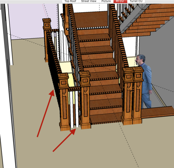
After I fitted everything up I realized that there is an open floor in the 2nd floor hallway that also needs a railing. I will print another attic set, since I know it will print perfectly, and trim it to fit this space. (arrows). The gap is partially due to having the 2-3 floor stairs 1 scale foot narrower than the 1-2 flights. I didn't think the attic deserved such a big stair.
Attachments
Forklift truck is getting ready for assembly now that the wheels are complete. They printed without flaws, cleaned up well and fit where they're supposed to.
Here they were as they came off of the Machine. I tried to keep as many supports off the lug nut detail as possible, although I still had to remove some.
After cutting the part from the base, here's what it looks like. At this point I put it in the UV box to cure it. I was careful to trim the supports away from the part so there was something left to grind off. If you clip too close it can break out of the part and leave a divot which requires filling.
After curing and sanding, here's what they look like.
I tried the wheels under the body and they work pretty well. I'm going to start working on some scratch-building to get the mast attached to the body and build the tilt cylinders, handrails and the glazing.
THC: I finished applying the rest of the roofing "tin" to the shed. Using the transfer adhesive is challenging to say the lease. Because the sticky side is outward facing when it's on the roll, it's very easy to get stuck to it while handling it. When it sticks to you, the adhesive leaves the backing paper and is basically toast. It's not really usable as it balls up into a sticky mess. You have to keep the wrapping sheet under the roll so it doesn't stick to the workbench.
I cut a 5/16" inch strip with the backing sheet attached. Yes, you can cut it with a scissors. I applied it to the cabin roof peak first pressing it half on one side and then half of the other. I was then able to just apply the wine foil peak trim and it stuck like crazy. It is a strong adhesive!
Meanwhile, I'm printing another set of attic rails to work for the 2nd floor railing. Instead of designing another set just for this application, it was easier just to print it again and then cut it up when finished. It's nice since once you get a print that is successful, as long as no parameters change, the next print will be successful too. It was how I was able to print all those windows. The EPAX non-FEP film is very reliable. Once the machine is lined out and working, it just keeps on making parts. I no longer use any teflon oil on it. I found that technique to be dubious at best. I just received another order of film from Amazon.
There's lot of stuff people can do with the time we have at home. You can read, listen to music, exercise, binge watch TV, etc. Most of these burn time, but when done there's not much to show for it. One of the nice things about being a maker is that every day I work in the shop something is created that says "I was there", even when I'm not. It's very gratifying to make progress on all these disparate projects each day.
Attachments
@Trainman2001 posted:There's lot of stuff people can do with the time we have at home. You can read, listen to music, exercise, binge watch TV, etc. Most of these burn time, but when done there's not much to show for it. One of the nice things about being a maker is that every day I work in the shop something is created that says "I was there", even when I'm not. It's very gratifying to make progress on all these disparate projects each day.
How very true!!!
@Trainman2001 posted:Spent all day working on the printed stuff. Got the stair built, and fixed those fancy interior doors. The fork lift truck wheels are done and hanging on the machine. They printed well also.
I cleaned and assembled the attic railing system. I did have a couple of minor fractures, but Bondic fixed them up.
I cleaned up the wonderful print of the 1st stair flight. I then used Bondic to hold it to the railing system. All of these supports were removed abrasively. There wasn't a single flaw on this part.
After assembling the stairs I had to fix a weakness. The 1-2 flights are held to the 3-4 flights by just some Bondic at the bottom of the adjoining newel posts. That joint didn't hold up well at all. So I drilled and pinned it in two places. It won't come apart again and I can be secure in the knowledge that the alignment would be stable.
After assembling all the flights I measured and cut a piece of foam core to serve as the wall next to the first flight. Most if not all of the interior walls will be foam core only because it so easy to work with. I'm going to fully enclose the stairs in their respective walls and install it as a module.
I then decided to tackle those damaged interior doors. I conceived that i could separate the top rail of the door frame in SketchUp and just print that bullseyes included. Then I could cut off the misshapen parts and glue on the new one. I chose to print them directly on the build plate (no supports) and since they were so small they printed in 15 minutes. I produced 10 in one go.
I used the belt sander to remove most of the bad molding, and trued the edge with the precision sander. I glued the bullseyes back-to-back so there would now be bullseyes on both sides of the door, where there weren't as I originally printed them.
And here are the fixed doors excepted for the one with the door knob that appears to high. It's because I glued the new trim on the wrong end of the door DOH!! I will remove tomorrow and do it correctly. They're not perfect, but at least there are no divots caused by support removal.
I also printed some fancy baseboards. Some on supports others on plate directly. I'm going to see which comes out better, although considering how well the door trim came out I pretty much know which one I'm going to pick.
After I fitted everything up I realized that there is an open floor in the 2nd floor hallway that also needs a railing. I will print another attic set, since I know it will print perfectly, and trim it to fit this space. (arrows). The gap is partially due to having the 2-3 floor stairs 1 scale foot narrower than the 1-2 flights. I didn't think the attic deserved such a big stair.
Trainman2001,
You've done a fantastic job on the staircase. I can only imagine the time and energy spent to try and figure out how overcome the various obstacles due to the printing process. My hats off to you!
Thank you. I just keep moving forward.
I needed to put the lighting into the shed. I should have done this before the tin went on. I was fighting to keep from completely deformed it. I want it to be a bit ragged, but not destroyed. I'm using grain-of-wheat bulbs and will probably lit by 12 volts DC (unless I tie them into the 14 volt power running to the switch machines.) At 12 volts, they're not very bright, but that's not too objectionable for such a rustic structure.
I put the two bulbs in parallel so they both get the full voltage. I wrapped their leads around the roof trusses and then ran them over to one side. I used the contact cement dots to stick the wiring to the walls. I may throw some paint on them to hide them a bit. They're really standing out there.
I went to test light them with my little rig and nothing! Since they were in parallel, a single bulb failure wouldn't kill the whole circuit. I got the voltmeter and found nothing coming from the little 12VDC ac adapter that I've been using for years to test my LED circuits. I substituted this (trashed it after removing the leads) and was rewarded with 12 volts DC and lights that lit. With the room lights blazing, they won't be noticeable, but it will look nice with the lights out.
The instructions called out a plastered or tarred valley flashing, so I mixed up some Milliput 2-part epoxy putty and put it on. Tomorrow I will attempt to paint it to look like old filler. We'll see.
There is a wood platform for the tie hacker to stand on. It was a very quick build and I aged it a bit with some dirt and oil stains (Tamiya Clear Smoke).
I also finished printing an cleaning up the last railings that will cut up to serve to save people from toppling over the stair well on the second floor.
Right now I'm printing a 1:1 part… it's a hexagonal screw driver bit holder. It was something I found on Thingaverse and is something I can use. In about the first 15 minutes the z-axis was starting to make the binding noises it does when the axis is jammed by something. The only other time this happened was when I had a failure and forgot to clean the lumps off the FEP. When the Z-axis attempted to set zero, it was held up from going to the bottom and the axis was rebelling noisily. This time it was different. It was when the axis was raising. I stopped the machine, removed the platen, and the vat. After emptying the vat it was pristine with no resin sticking anywhere. I lubricated the lead screw, reset the vat leveling and put it back together again. Even the touch screen was acting disturbed. I restarted the print and it worked fine. Don't know what happened… But the print completed successfully. I upped the layer thickness from 30 to 50 microns. I didn't need a fine detail setting for this tool. In fact, the design was originally for a string printer. I have a ton of these hex tool bits and this will keep them in one place. I also have a job set up to make a two-part iPhone holder to use with a tripod.
Attachments
The lighting looks good. All the details are coming together!
I am still impressed with the detail of the staircase!
The shed looks really good, Myles. I noticed the wires are running between two vertical studs. Why not make a channel by adding vertical sheathing between the studs? I know it doesn't match the rest of the shed but will blend in better than the wires.
I did nothing today except trying to fix a failed touch pad on the 3D printer. And I didn't succeed. Right now the printer is sitting in pieces and is non-functional. The story goes like this, and I'll try to be brief.
I had a new touch pad and when the touch pad really starting acting up (not responding to touch or responding very slowly), I decided to replace it. After removing the old one I found a lot of resin had leaked in behind and I didn't think that was so good. To stop the leakage, I put two layers of servo tape to close the gap between the screen and the housing. I did test the screen before putting in permanently into the housing and it worked perfectly. After reassembling with the added seal, I tested it again and the screen while lit was completely unresponsive. The seal was putting pressure on the touch screen and making it inoperable.
I took it all apart and that's when the poop hit the fan. I had to use an Xacto knife to cut the servo tape which was now firmly holding the touch screen. In the act of doing this I sliced a part of the ribbon cable connecting the screen to the motherboard. The new screen came with a new cable. Problem was, I didn't really know how this cable was connected. The connection fitting on the board was very finicky and took me almost an hour to get it attached.
I tested it again and had a black screen.
After the third disassembly I found a video from Elegoo on replacing the motherboard as I wanted to see how this cable was connected.
To make a long story short, I don't know what is correct. I think the cable is twisted. In one video, the non-printed side was facing up on the motherboard connector, but on the touch pad it was ribbon cable's printed side that was facing up. I don't know what's supposed to be up. I took pictures and am going to send them off to Elegoo and get some help. I may have blown the touch pad, motherboard, neither or both.
Bummer!
Luckily, if this is the end of my printer, I did get all the parts for the House completed and the fork lift. I am running out of subjects for printing… oh well...
That's a bummer indeed! I hope the Elegoo folks can help you
@Trainman2001 posted:Luckily, if this is the end of my printer, I did get all the parts for the House completed and the fork lift. I am running out of subjects for printing…
...AND, you will have an excuse to buy the big, new Saturn! ![]()
Myles, You will never run out of things to print. The next project build will require more parts that are best printed to save time. Doors, windows, cornices etc The things that make your projects stand out from most of us.
I am also waiting a response from Elegoo concerning my membrane switch panel. Keep us crazy 3D printing nuts appraised on your solution. We all learn from each others problems.
Gerry G
That is tough luck. Hope it gets resolved soon. Good luck.
Pot pourri day!
Elegoo is sending me a new touch pad, soif I can get the ribbon cable properly connected it should be back in business. Funny thing… when I was taking the printer apart a long (about 2") Phillips Head screw fell out. After searching I found that one of the four screws holding on the stepper motor's end bell had fallen out. I had to remove the upper body bolts to tilt it enough to reach it with the screwdriver, but I did get it refastened… so that's a silver lining.
I'm also thinking seriously about upgrading to the new larger, improved Elegoo Saturn. It has about 2.5X the build volume which would improve productivity greatly. Of course my wife immediately said, "So what's the rush?" Actually, it would be nice to be able to print parts for a project like the House in a week or two instead of five or more weeks that it's taken. I could print an entire O'scale prime mover like I do for the HO versions. So there's that. It also has a double leg Z-axis and finally moved the USB port to the machine's front. We'll see.
The trouble I had in reassembly was these small ribbon connectors. Here are the two on the touch screen. You only need to connect to one of them and they both go to the same circuit. The one of the right is where I broke the ribbon clamp off. The middle one is intact. You slide the ribbon under (or over) the clamp into the connector and then push the clamp towards to the connector to lock in the cable.
Here's one of the broken clamps. You can see the little tang that has a barb is missing on one side which is what broke and let it fall out.
There are many kinds of ribbon connectors, but this kind seems to be the most insubstantial and are very fragile.
I finished up the hex bit holder and put it to use. The honeycomb is sized very close to nominal and you have to wiggle the bits a bit to get them in.
I took Pat's suggestion and built a "wire blind" to conceal the wire bundle coming from the shed roof. I made it a little peaked affair since the wiring was a bit thicker than the wall's stud height. Once again, applying a good idea from one of my faithful followers worked out well.
From the viewing distance. The wires will be very obscure, which is just the effect we wanted.
The thing I did was get to work on the forklift truck. I had several things to do before assembly could be done. I had to replace the steering wheel and one of the seat armrests. I originally thought to find a piece of tubing the right diameter and slice off the steering wheel, but couldn't find the right diameter. I then measured the stub that remained on the steering pedestal and scribed two concentric circles on 0.040" styrene sheet. I drilled out the i.d. and then trimmed the circle with cutters and then sanding sticks and files to create the o.d. I glued it onto the stub with medium CA.
For the armrest, I first created a thin (0.010") styrene profile of the broken armrest. I glued this to the seat and then filled it in with Bondic. During the sanding and shaping process, the styrene piece started to come off. Since the Bondic was now self-supporting, I pulled off the plastic and continued finishing the armrest. After a coat of primer I took this image. I still have to detail paint the interior and possibly put some more details in it.
Neither the wheel of the armrest is perfect, but it's better than missing or broken.
I needed to create a new exhaust system. I wanted the pipe to be 1/8" brass with a brass muffler. I thought I had enough telescoping brass tubing to fill the gap between the pipe and the muffler tube. I didn't. Instead I found some Plastruct tubing that was almost the right diameter. It's i.d. was the 1/8" I needed, but the o.d. was just a scosh too small. I wrapped some 0.015" styrene around once and it became a perfect press fit. I didn't need any adhesive.
I bent the exhaust pipe using the K-S bending sleeve of the right side and then cut the outlet at a bias. I did use CA to hold the exhaust pipe into the muffler.
I removed the one existing handrail on the cab and made two new ones out of 0.032" wire (one brass the other Phos-bronze). On one side there was the mounting plates still there, but on the other they were gone so I substituted some wine bottle foil. After trimming, they're held with thin CA.
I still have to make two grabs for the sides of the chassis. I did locate and drill the holes for these.
The last thing I did today was remake the missing running board. Again, I used 0.040" styrene and shaped it to fit the rabbet that I had carved into the chassis. I did have to do some final cleanup of the mounting and taper some of the running board's edges so it fit snug. I then used some Bondic to fill in any remaining gaps.
I added a shim to the mast's bottom so it would tip back a bit to help hold the prime movers in place when they're being carried. I still have a few things left to do. I need to make a couple of tilt cylinders and their clevises, and I have to get it ready for paint. I'm going to prime the parts separately and also paint them separately. I need to do the cab glazing as well. It's turning out to a decent little project.
Everyone have a great weekend.
Attachments
I'm glad they are sending a new touchpad. Yes those ribbon cable connectors can be a problem. That is a slick holder for all the bits!! They can get away from me as I have acquired a few with different tools.
The wire blind looks great! Great suggestion, Pat!
The fork lift is coming along great!
Ya know Miles, I bet you could sell a bunch of those stair cases for two storied buildings especially designed for the multitude of korber kits out there!
Thanks! Just because “I could” doesn’t mean “I should” or “will”. It is a ton of work and a high failure rate. If or when I get the Elegoo Saturn, it would greatly increase capacity so it would reduce the number of cycles, but wouldn’t reduce the post-print workload. It means they would be expensive at $100+ for three stories. I would need drawings for the Korber buildings to get the height correct. In other words, it’s complicated.
would you be a customer?
Today we are officially off the cable! I took a box with three cable boxes, ac adapters, wiring and remotes to Spectrum, our cable provider, and we're now on YouTubeTV. The net reduction: instead of $187.00 a month we're now at $69.99 for 200mps Internet and $49.99 for YouTubeTV without losing any channels we had before = $119.98. It's the first real break we've had in cable costs in years. Now we're contemplating doing the same with the cell phones. We were paying $100/mnth for Verizon at 4GB data and two lines. We're using less than 1 GB/mnth. Spectrum has each line with 1 GB and unlimited talk and text for $14.00/mnth = $28.00. They claim no difference in service performance. Of course Verizon disagrees. Does anyone have any experience with this? Please feel free to share. We could get two new iPhone 11s and the service for less than our Verizon bill was. My son in law does did both of these switches and says "We're nuts if we don't take advantage of saving this much money!" He can be direct at times...
So because of all this techy stuff, I didn't get a lot done. I did get the other handrails on the forklift and started building the stand for the Cabin's oil tank.
I used the same 0.032" phos-bronze for the railing. I measured the location of the holes I drilled and then drew a simple diagram on a piece of paper so I could make it fit properly. After I bent the first one using my MicroMark Parallel Jaw Loop Making Pliers, I used the first one to be the template for the other. After fitting them to the body I used a drop of thin CA to lock them in. I then trimmed and power-filed the remaining metal stub sticking out below.
The last bit of wood crafting for the Cabin is this little model of a timber stand for the included resin oil tank. It was supposed to be out of 6 X 6 stock, but for some reason, I can't find where it went. I suspect it may have slipped off the work and into the trash can. Anyway, I ended up laminating three piece of 2 X 6 together to make the stock. No one will know. In building these frames I had flashbacks at building the pile of them for the L-Girder layout in the other end of the basement. It made me think that I could build a miniature O'gauge layout like mine. It would be a little less than 3" wide and about 10" long. Just think'n.
I had just glued the legs to the under framing. When dry (tomorrow) I will put X-bracing between the three leg sets. I then turn it over and finish paving the top surface with 2 X 6s. It gets some NBWs of which I have a bunch.
Attachments
Crazy thing happened yesterday… I was going to put one of my carbide micro-drills back in its case, and opened the wrong one by mistake. It was the one holding the super-fine 0.010" drills, and one of them poked me in my left thumb. They're finer than a sewing needle. It bled very little. But it hurt later at night more than a simple finger stick should. I began thinking that maybe the **** thing broke off inside my thumb. Today I checked the box and sure enough, the one that stuck me broke off and it's in my thumb. It's sore, but tolerably so. It's tungsten carbide and I think it's pretty inert and probably won't cause a reaction. I've had my tetanus shot. To get it out would require minor surgery since it went in almost vertically.
Meanwhile, I did stuff today.
I primed all the forklift and Hacker's Cabin parts. Before priming the hacker's parts I cleaned them up. They're all resin castings. I thought the tables would have legs, but they're just the tops with lots of tools and junk molded on. So I needed to put legs under them. I drilled the tables with a #38 drill which is a nice tight fit with the scale 4 X 4 lumber. When the tables are painted, I will construct an under frame using the 4 X 4s and other strip lumber for bracing. I'm surprised the kit didn't include any drawings or instructions on constructing the tables.
While this was drying, I went back to work on the roof. I painted the milliputt fake valley flashing a nice dark, dark gray to simulate older tar. I then mixed some color to touch up the areas where the putty was on the shingles. I used the same color to randomly pick out some shingles to make them darker to add some variety. I then mixed up an alcohol wash and did the whole roof. The peak capping has really taken on the look like galvanized steel. I still may use some strategic weathering powders to further age it.
I also finished the oil tank rack. I would have like to use a bigger style NBW, but didn't have any and didn't want to take a trip to the LHS and get some more. But you get the idea. I still have to add some selective rusting to the hardware.
I fit all the forklift glazing. For the front and rear glass I used a big piece of masking tape over the opening. I held it up to the light and with a brand new #11 blade I cut the tape along the frame edge. I then put the tape onto some clear styrene sheet and cut it out. After some final trimming, it fits the opening perfectly. I'll glue it in with Testor's Canopy cement.
For the side glazing I used some manila file folder stock to make a pattern of the side windows. I'm making the windows cover the entire side wall to avoid the difficulty of creating that small triangular rear windows.
After getting the pattern right I again transferred it to the styrene. The two sides were almost identical, but there were slight variations. The 3D printed object is not a perfect geometry.
Here is the side glazing in for fit. All the glazing will be installed after all the painting.
I glued a strip of 0.030 square styrene to the rear edge of the side windows that will be the attachment point for the rear glass. I used the masking tape method again to find the size of the rear glass.
I needed to make new lift cylinders for the lift mast that didn't hold up during cleaning. I'm using a piece of brass tubing with a perfectly fitting piece of drill rod. I will not have to fake the polished steel look of the cylinder since it's actually polished steel. The brass will be painted mast color. These will be epoxied in place.
I airbrushed the body's first coat with Badger Model Flex UP Armor Yellow. I'm going to paint the truck in full UP livery with various parts being Harbor Gray contrasting with the yellow. I'll mask this tomorrow for the gray. All the upper surfaces will be gray and below the belt line on the side. The mast and forks will be semi-gloss black. The wheel hubs are yellow and tires will be Tamiya Rubber Black. I also finished painting the cab interior. Cab is not connected in this image… just sitting pretty.
Attachments
Ouch!! My dad stepped on a sewing needle when I was little, and it broke off. The surgeon dug around in his foot and found it was lodged in a tendon so he left it there considering he had already put a big hole in Dad's foot. He still carries it with him over 55 years later. Hopefully you won't have trouble.
The cabin looks great, and it is remarkable what a little paint does for these wonderful parts you made.
The cabin and the forklift look great, Myles. I love when a model is finally taking shape and you can finally picture the final product.
Thanks. I agree and feel the same way. I'm always amazed to start with a pile of stuff and end up with something unique.
I did a weak attempt to see if I could dig out that micro-drill, but didn't get very far. It's really not hurting so unless I go to a hand surgeon and get an X-ray and then have it surgically removed. Since I take Eliquis, I would have to be off it for 48 hours. If it's not bothering me, I'm probably going to leave it alone.
First it was an exercise day. My wife is walking four miles each day. I prefer to work on the recumbent bike and elliptical and watch TV. I've been watching the entire library of Twilight Zones on Netflix. They were really dark!
Also did errands and bought a new Netgear Mesh Router with three pods. We're watching a lot of TV out in the sun room and we got rid of cable this week so we're entirely dependent on Wi-Fi to give us something to watch. The Router we did have was at the furthest point away from the sun room and the signal was awful. We're getting 200mbs at the router and 9 in the sun room. The new one has a main router next to the modem and two more satellite units that boost the signal anywhere you want to put them. Much better.
Why am I telling you all this? Because I only had an hour to work today.
In that hour I got the second coat of paint on the lift truck. I masked it and airbrushed Badger Model Tech Harbor Gray. As you'll notice, I missed a spot with the tape. The Tamiya tape and the yellow are similar and I missed putting it on one part of the engine compartment.
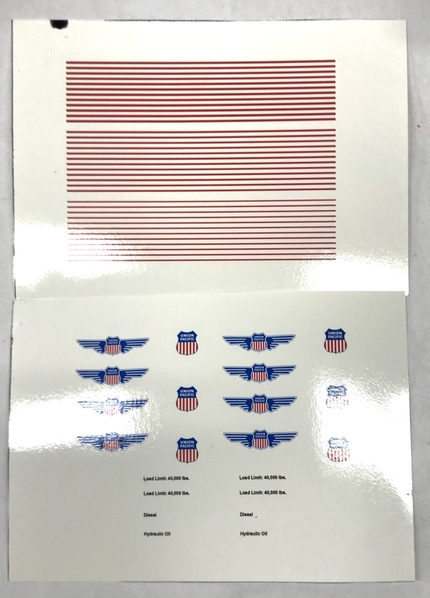
To get the yellow to match when I do the repaint, I will have to shoot some white primer first since shooting yellow over the gray will produce a different yellow than the rest of the yellow. I am also going to attempt to put the thin red lines that demarcate the colors on UP engines. I may produce some decals to do it. I will have to repaint the railings since I chose to not mask those either.
Attachments
Some of today was spent wrestling with our Capresso coffee grinder. I took it apart for cleaning and put the parts I could into the dishwasher. It's a burr grinder with a rotating cutter head and a fixed chamber with teeth also. The fixed chamber is removable for cleaning, but doesn't go in the dishwasher. I put it there once and the cutter rusted. It can go into the machine two ways: the right way and the wrong way. I wanted to just put it in the machine to hold it while the rest got washed. Of course I put it in the wrong way. I've done this before. This time, for some unknown reason, the three lugs that should just drop into the three matching slots actually went underneath the outer house and I could no longer remove it. I tried prying it, spreading the housing and nothing worked. Finally, I used the Dremel with a 1/16" router to trim just a bit off to relieve it enough to get the darn thing out.
One of the things I did to relieve it was to remove the burr. That didn't do anything. But after I got the outer grinder off, the plate under the burr let go and a mechanic's nightmare ensued. Three ball bearings and three springs came popping out of the assembly. I hate when that happens. I reassembled it as best as I could and took it upstairs to put it together, but the burr was off center and when I started grinding some coffee with was working very hard and created very fine espresso powder. Something was wrong. At this time my wife went on Amazon and bought another one. This one was six or seven years old. I took it back to the shop and took it apart again. This time I put the bottom plate into the ultrasonic cleaner. I decided to reverse the order of the ball bearing/spring mount. Instead of the balls on the bottom with the springs sitting on top, I did the opposite. When I put it all together and tried it, it worked perfectly. I cancelled the Amazon order.
Now onto the projects.
I masked and repainted the forklift to fix the missing yellow part. I made some circular masks using my specially prepared dividers with one leg ground to a chisel edge parallel to the rotating direction. I used these to mask the hubs. I airbrushed the tires NATO Black (a very dark gray). After de-masking I touched any leakage spots with Harbor Gray. I brush-painted the railing using Vallejo dark yellow and left it sit to dry thoroughly.
But before doing this, I spent time on the laptop making some graphic decals. I found a website that had PNG vector drawings of UP logos. I was able to import them into Mac Keynote and size them to fit the space I wanted.
http://pluspng.com/union-pacific-vector-png-1541.html
Vector drawings for the uninitiated, don't change resolution when you change their size. I had some trouble with Keynote creating objects of the same printed size as they were on the screen. I wanted the shield and wings to be 1.3" wide for the forklift's tail. I set up guidelines for this dimension and sized the object on the screen to those guides. When I printed a test sheet (luckily I printed it plain paper and didn't waste decal paper) it came out way undersized, about 2.6X undersized. With trial and error I got them to print at the desired size.
After printing I sprayed them with Testor's Decal Coating. Remember, inkjet ink is water soluble. You must seal it with a decal film liquid before cutting them out and soaking them. I printed these all on white background film. Unless you have an ALPS printer you actually can't print white. This requires some careful trimming. In writing this I realize that the lettering I printed won't work since it has the white background. I'll need to reprint them on the clear film. I needed the white background for two reasons: the logo has white in it, and the red stripes would be much more vibrant with the white underneath. The base color won't bleed through.
I printed the stripes in three widths not knowing which would work the best. Actually, I think the bottom stripe between gray and yellow is thicker than the top between yellow and gray. I make multiple copies always since you're going to waste and entire piece of 5 X 7 decal film anyway, and I will probably screw one of them up.
The lift truck is starting to look pretty spiffy. Notice that the stack is painted Tamiya dark iron. I will go back and add soot in selected areas. Weathering and selectively picking out creases and details will really make this model work.
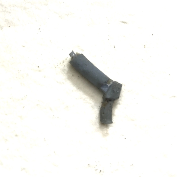
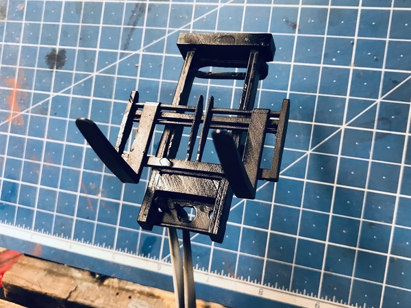
I needed to fabricate new tilt cylinders. Here was the 3D printed one that broke off during cleaning. The lug on the lower right connected to the main deck.
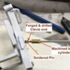
I machined the cylinders out of brass that was exactly the same diameter (3/16"?). I found some steel rod to serve as the piston rod and drilled the brass with a 0.078" drill. I then literally forged the rod end to flatten it, drilled with the 0.032" carbide drill and soldered a piece of same-sized phos-bronze to serve as the pin. Nothing simulates steel better than steel.
I still have to figure out how to make the other end that attaches to the deck, but will do that tomorrow. I need to finalize the lift cylinders also. When they're both done, the mast can be painted and installed. We're getting near the end. I may make the attachment block out of styrene, although it would be fun and more secure to make it out of metal (brass or aluminum).
I want to finish the lift truck before getting back to the Cabin. Once it's done, I'll finish up the cabin.
Attachments
The lift truck is really shaping up nicely! The metal lift cylinders certainly won't break. That is some neat information on the vector drawings. I was the uninitiated. ![]() My drawing skills are still in the pencil and mylar stage.
My drawing skills are still in the pencil and mylar stage. ![]() It's amazing how that was the going technology when I was an electrical designer back 40 years ago.
It's amazing how that was the going technology when I was an electrical designer back 40 years ago.
A lot of folks don't understand the difference between a bit map and vector graphic. Our cell phones take bitmap images and JPG images are. They are created from a series of pixels each with a specific color and intensity assigned as a computer value that is interpreted by the display software. As you enlarge a bitmap, you begin to see these pixels and depending on the cameras resolution, you could quickly reach a point where the object looks like it was created in MineCraft. A bitmap image is only really good at the same resolution as it was created.
All of the photoshop and paint programs make bitmaps.
Vector drawings are mathematical constructs. Instead of discretely creating and object out of individual colored bricks (pixels), the vector describes the geometry as mathematical objects. Instead of a line consisting explicitly of X-number of pixels. The vector line describes a line of X-width and Y-length. Curves are defined parametrically by their radius, etc. Therefore a vector can be shrunk or enlarged infinitely and never lost it's shape. It doesn't pixelate. All the drawing programs, Adobe Illustrator, CorelDraw, CAD programs are vector based. STL files are created from vector images.
Today, I wrestled with making the holding lugs for the tilt cylinders. I realized why I was procrastinating on this particular part. It was a challenge. At first I cut out a series of 0.040" brass pieces that I was attempting to solder together to create a real slot in which the cylinder lug would pretend to rotate. This wasn't working out too well. Plan B was to cut the entire block out of piece of thick brass using a jeweler's saw. This proved successful. Cutting it was no big deal and I used some TapMatic Brass cutting fluid to make it go faster.
Final shaping was done by holding the lug in vise grips and surfacing the facets on the belt sander. I drilled the bottom for the phos-bronze pin, and then drilled the face with the 0.078" drill for the piston rod. Of course I broke on of the carbide drills in the hole and broke the big drill in the process of trying to manhandle it out of there. I re-sharpened the drill twice before I got the holes done. I drilled the forklift deck to receive the mounting pins.
I held the mast in place with tape and test fit the cylinders.
Then I tried to put the cab in place, and of course, the lugs were too fat. I put them back in the vise grips and reduced their width so they just cleared the cab size. This is actually the way they should have fit. I just wasn't paying attention to width. It was an easy fix. finally, after all fit correctly, I epoxied the lugs to the deck and will paint on Monday.
While this was setting up I painted the mast. I did a precept of steel and then an overcoat of semi-gloss black. I will lightly sand the black off to expose the "metal" beneath to show some wear. I kind of like the texture created by the 3D printing process. It looks like cast steel.
Have a great weekend. If you go out, wear a **** mask. It's not to protect you, it's to protect me.
Attachments
Thank you for explaining vector drawings. I knew the CAD programs had to use something different from bitmaps and jpeg, but didn't know what.
The lift truck work is looking great!
i always have my mask. I want to protect you!! ![]()
Fonts are vector drawings. This allows you to change the font size without losing the integrity of the font.
Yup! That's right… until you export the drawing as a JPEG and then it all becomes a bitmap again. I'm having a ton of trouble with my CorelDraw application running in VM Fusion. VM Fusion is a parallel program allowing me to run Windows on my MAC. With every VM upgrade the Corel performance is getting worse. Now it's dysfunctional. It loads, but mouse and keypad response is almost non-existent, and then when a dialog opens up, there's the graphics, but no text and nothing responds when you click it. I've messed with parameters, but they're not working. I can't upgrade Corel because I don't want to part with the $250.00. Going back to Adobe Illustrator isn't such a good choice either since it too costs a ton of money for a casual hobbyist like myself and it doesn't do scaling without paying even more money. My laser cutting guys uses Coreldraw and Adobe doesn't have a conversion to that software. There are very few vector drawing choices on the MAC. I'm getting bummed. I need Coreldraw for the laser projects I have in the works. Any ideas?
Okay, ignore all the above. The problem was me. I had upgraded the VM and there was a chunk that had to reload during the Windows boot. I was interrupting this while trying to start CorelDraw and screwed up both. This time, I just sat and waited. Even though Windows seemed fully loaded, suddenly a dialog opened stating that VM was updating some aspect and it went through a series of status bars and finally finished up. This took a while. It was a new feature enabling VM fusion to more easily access the MAC files. And then I started CorelDraw and all of it worked! Whoopee!
Spent the whole session working on the forklift. I worked on the mast lift cylinders and painted the tilt actuators. I finished the decaling.
To provide a more solid mounting for the lift cylinders I bent and soldered some thin brass sheet to form some brackets. These were cleaned up in the ultrasonic and then primed. I epoxied them onto the cylinder base. before doing that I wrapped some Chartpak tape around the ends to build up the profiles. These were then primed and painted semi-glass black.
I used 30 minute epoxy and held everything in place during cure using some heavy blocks.
I tried them in position for fit. My cylinder design is unrealistic and wouldn't work. It's using the retract position to lift the load which is backwards. What is needed is a pulley system to reverse the thrust so the raising is on the more powerful forward stroke. I may build that. Also my cylinders are too long leaving not enough piston travel. Now I will ask you guys, "Should I worry about this?" When the assembly is also epoxied to the mast I will go back and paint the brackets and touch up the cylinders. The polished drill rod really looks good as a piston rod.
The emblem decals were pretty good except for one annoyance. Printing on white background decal paper means you have to trim the decals exactly to the colored edge. I used a very sharp blade and carefully just cut deep enough to penetrate the decal film. Then I cut the decal out of the sheet way outside the decal design.
The line decals were another thing entirely. These too were printed on white background decal paper and trimming them to eliminate any white outline took a lot of careful blade work. Then getting on was a pain. Because the ink is water-based and is sealed by the top coat, everything is cool until you've manipulated the decal a little too much and you break the top coat allowing water and decal solutions to get to the ink. This degrades the decal quickly and made for some finicky work and a lot of redos. I will go back and do some fine brush touchups tomorrow.
For future recommendation I would say using custom made inkjet decals for striping is not a good application. For the logos it worked very well.
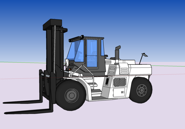
Just noticed. The location of the tilt cylinder lugs precludes opening the cab door. They were originally further up on the deck. And opening the doors inward is blocked by the driver's seat. Oh well. That train has left the station. In looking at the originally art work I can see why. My cab is too far forward. The cylinder lugs are in the correct place. I could cut the engine box to move it back. There's also some body work under the cab that was originally on my print, but I removed in error thinking it was also part of the cab. It wasn't. And I also can see the chain coming down outside the mast to lift the forks. That I can add without too much hassle.
When I thought about making this lift truck, I had no idea that it was going to become such a comprehensive project. I could have chosen a simpler prototype, but the size of the loads dictated a pretty large machine. And then once I decided to do it in UP livery, I just complicated it even more. I'm not happy with the interior yet and will maybe do some more work in there too. As always, I go whole hog… AMS in action.
Attachments
The forklift is looking good. Nobody but you will notice the small detail errors that you pointed out. You can leave them alone and nobody will notice. The question is will it bother you when you look at it? If you can live with it, leave it alone. If not, fix it.
But, you know me. I noticed it and had to fix it. And fix it I did! I elevated the cab, removed about 1/8" of the engine cover, and found some (although a little over-scale) some roller chain to act as the fork lift mechanism.
I woke up thinking about this chain question. You can tell how unstressed my life is that I can wake up in the morning thinking about nothing more serious than how to simulate a lift chain on a train model. Life is good! I remembered that I still have an old 1:6 scale Tamiya Honda in-line 4 motorcycle engine model floating around the basement. I built the model in the mid-1980s. It had a simulate roller chain that looked like it was long enough to provide what I needed. It did.
I disassembled part of the model and cut out the chain. I mounted the bottom end onto part of the fork assembly using some phos-bronze pins and just CA'd the top to the mast. It's a tad big, but it tells the story. After I installed the chain, I epoxied the lift cylinder brackets to the fork assembly and the upper end under the guard at the top.
Also notice some bent Photoetched junk stock that acts as a shield for chain connection.
When the epoxy cured I masked the piston rods with some liquid mask and repainted the semi-gloss black.
I measured and cut the 0.040" styrene to make a new base for the cab. I also used a razor saw to remove about 1/8" of the engine cover. I finished sanded it with the power mini-sander. The base sits under and just inside the outer perimeter of the cab. I used solvent cement to hold it together.
After priming I epoxied the new base to the chassis. I used epoxy since it gave me more working time and I was gluing styrene to resin. The resin is unaffected by the solvent cement. When it cured I filled a couple of gaps with Bondic and air brushed it with Harbor Gray. I also went around and did some hand touch up on the striping. The cab is not fastened on in this image. I have to install the interior and glazing before that happens. By raising the cab and moving it rearward a bit now clears the tilt cylinder nicely. I'm glad I did the fix.
The brackets I made to hold the mast cylinders now interfere with the new front panel. I have two choices: 1) try and trim the extra brass from the brackets or 2) cut some relief openings in the front face. I'm going with choice 2 since I think that the epoxy would let go in attempting #1.
While the epoxy was curing I painted the first coat on the plaster cast stone parts for the Cabin. I used a palette of various grays and earth tones most of which were from a Woodland Scenics tinting set. I used a lot of water.
The next step will be to seal the plaster and the apply an alcohol wash to weather it and create the mortar lines. After that I'll use some weathering powders if needed. The colors muted down very nicely. They went on darker and I'm glad to see it.
Until next time.
Attachments
Great job as always. You have the patience of a saint.
Steve
Wow! both projects look great!


