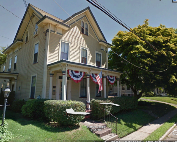
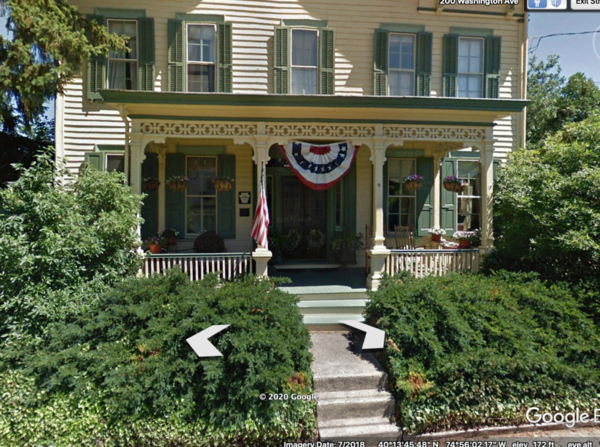
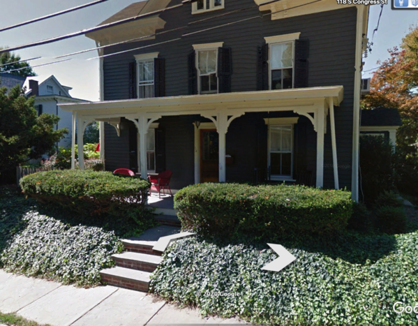
Thanks guys! Mark, it may be mine too. I sure hope it fits. But, I'm thinking that many Victorian houses in small towns are very close to the street. I have photos in Newtown, PA (our old haunt) that bears this out. Here are some screen shots from Google Earth that shows how close to the street these old homes can be in a town environment. Not much of a front yard. Mine will even have a bit less.

Screen Shot 2020-12-26 at 8.21.45 PMScreen Shot 2020-12-26 at 8.21.09 PMScreen Shot 2020-12-26 at 8.17.49 PM

Newtown, Bucks County, PA is an interesting place. It was founded in 1686 by William Penn and has homes still being lived in that date from the late 1600s. There are three distinct styles: real honest to goodness colonial homes that were built when people were still subjects of good ole King George. Then there are a load of wonderful Victorian Houses and then a smattering of 20th century homes. It you build a house in the borough today, you must conform to ridiculously strict codes. For example, "No non-wood siding", no bricks with holes in them, no MDF wood trim, etc. There are no McDonalds and only starbucks franchise in the borough. In the township surrounding the core, the zoning rules are more relaxed. As a result, it's kept its colonial feeling to this day. We were sorry to move away from it, but we couldn't afford a home in the borough. A reasonable sized Victorian would be in excess of $1.0mm.

Attachments

Images (3)
  • Screen Shot 2020-12-26 at 8.21.45 PM
  • Screen Shot 2020-12-26 at 8.21.09 PM
  • Screen Shot 2020-12-26 at 8.17.49 PM

Myles, Excellent examples!  I can think of homes in Butler that are very close to the street also, though none built until well into the 1800s.  The first log house in what is now Butler was built in 1797, two years after my great-great-great-great grandparents Boyce established their homestead in the forest 15 miles from what is now town.  That is where I grew up.

I have heard of Newtown, but never knew anything about it.  Thank you for the interesting history.  Yes strict codes and cost are very prohibitive there.  My wife went to nursing school at Thomas Jefferson University in Center City Philadelphia.  She just spoke with a classmate living in Chester who said when her husband retires next year, they are planning on moving due to cost of living.  Many of the old homes in Butler can be purchased in good condition for under $200,000.  Ours in the township is worth about $175,000.  Neighboring Allegheny County is more expensive, but still a bargain when compared with Southeastern Pennsylvania.

I think you can get away with placing the model very close to the street and be very prototypical. 

Actually, many of the small towns in PA follow the same style. When you're on I-81N from Hagerstown, MD and you're heading to the York Train Show, you can get there by turning east on Rt 30. This takes you through several picturesque towns including Gettysburg, New Oxford and Abottstown. All feature a town squares, main streets and lots of early and late 19th Century houses. Half of Bucks county has towns with 200 year old buildings in it. West Chester is another stellar example of preserved Americana. I love it.

Ironically, due to the massive damage in the wars in Europe, there's much here in the USA that is more preserved than in the Old Country. Brugge Belgium is a good example. The main square as so decrepit that all of the "originally" Belgium/Dutch style buildings were re-creations of the original. In other words, THEY'RE FAKES. When the residents realized how much could be made on tourism, they re-created the architecture as a tourist attraction. I got this info from a good source. He was one of my Henkel colleagues who grew up and still lives in Brugge and who's father was involved in the project.

That could certainly be true. And that's exactly the story I'm going to tell folks when they wonder why the House is so close to the street.

The Brick Hotel is now featuring an upscale steak house and they're upping their game. We (used) to get back East about four times a year to visit friends and family. We have a favorite bar in Lambertville which is associated with the Lamberville House Hotel. It used to be call the Left Bank, but now it's just the bar in the hotel. They serve great food, and terrific drinks. It's a custom that we go there each visit for a lunch and afternoon Espresso Martini. I have lots of Lambertville pictures, but couldn't find them for this post. I ran out of patience looking through the 20,000+ images in my Apple Photo App.

Congratulations, Myles. The model looks amazingly like the painting.

Saint James, in Smithtown Long Island, is a historic area that maintains strict guidelines on architecture. The building that my club is ocated in, called Mills Pond House, is a 200 + year old house that is on the state historic records as a historic site. It is owned by the Town of Smithtown. The club is located in the basement.

Attachments

Images (1)
  • mceclip0
Last edited by Pat Kn

Myles, I hope your doing well, I’ll take a tour of your last 50 pages soon, your patience and attention to details, and now micro details is amazing, Thank You for posting pictures of all the amazing houses and inside detailing that your doing, when the pandemic gets under a normal control with folks getting vaccinated, we will visit again. Stay safe m stay healthy, pray continually. Great modeling and this is a really educational topic. Happy Railroading Everyone, Happy New Year...

Thanks guys! Happy Monday!

Larry, I too am anxiously looking forward to the time (sometime next year) when we can socialize again as humans are wont to and visit one another's layouts.

I communicated with the editor of Railroad Model Craftsman today and found out two important things. The Engine House article is still in the queue and he's interested in publishing an article about the House but… and it's a big but, it has to be publishable in a single issue, 2,500 word limit and 20 images. I can do that, but it won't be easy. There's a huge amount of meat in this project. It's really three separate and distinct areas of effort:

  1. Drawing everything. I had to learn new SketchUp techniques to draw some of the shapes especially the Mansard Windows.
  2. 3D printing: Hundreds of components were printed which took me right up the learning curve. Even today I printed the electric meter.
  3. Assembly: This only took around three months, but it was intense.

I will do my best.

Just two House items today. I got the back steps built, and printed and installed an electrical meter/mains hookup.

I finished building the Waste Management 2-yd Dumpster. I ended up creating two of them. The upper edge of the bin did warp and I had to do surgery/filling to make it at least workable. After painting and decaling, it will work just fine.

Dumpster Complete

On the second one, which was actually a better print, I smashed one of the lift channels when it got grabbed by the disk sander and smacked into the sander's table. I hate when that happens. I recreated one using some styrene. It's slightly bigger, but hey… it's just a dumpster and won't receive much attention.

Dumpster No 2

I have a Waste Management graphic that I will convert to a decal and apply after I paint it.

I have a laser cut kits to make wooden open steps from Rusty Stumps models. It consists of laser cut stringers and treads and a resin cast jig to hold the stringers in position during glueup. I needed to put a positive stop on the jig to keep the stringers aligned fore and aft. I tried gluing the stop onto the resin, but glue didn't stick to it. It probably is coated with mold-release. I then drilled and pinned the stop and that worked well.

HBTRR Stair Building Jig

As I usually do, I started using Aleen's Tacky Glue and followed it up with thin CA. The CA cures quickly in presence of the water-based PVA glue and then holds everything while the glue dries at its own pace.

HBTRR Back Steps WIP 1

I then notched the top and bottom steps to accept a piece of square stripwood and glued them in place. I topped it with a scale 1 X 3 and made a workable railing.

HBTRR Back Steps WIP 2

The electric meter is a print that I used before on my Appliance Store, but the foundation is a little taller so I went back to the original drawing and modified it. I also put a rib down the back of the conduits so they would be flat on the build plate eliminating overhangs and the need for supports. I printed it 8-up knowing that some would be scrapped. I actually only got two really good ones. I only needed one. Some of them had delamination in the thin parts. That's why I always print a lot.

HBTRR Electric Meter Print Output

After post-curing, cleaning it up, using Bondic to create the meter glass dome and then painting my "Galvanized Steel" mix, the piece was ready for installation.

I painted the steps neutral gray which is similar to the porch color. In this image it's just posing for the camera. I won't glue it in place until the House is set on its base. The utilities hookup is glued in. With a meter, the House can get its Certificate of Occupancy...

HBTRR Back Steps and Utilities

The steps are sitting a bit high and I'm going to shave some stock off the bottom of the stringer to lower it. The first step is taller than those that follow so there's some stock to remove.

With House building part behind me, I started, but did not complete, a major shop cleanup and some reorganization. I have a couple of workbench mod/build projects that I want to do to streamline some of the tasks I do. I want to move all the 3D printing stuff to a newly reconstituted table with a shelf above that will hold all the chemicals. I'll finish all of this over the next couple of weeks. Meanwhile, I'll be building the base for the House vignette.

Attachments

Images (7)
  • Dumpster Complete
  • Dumpster No 2
  • HBTRR Stair Building Jig
  • HBTRR Back Steps WIP 1
  • HBTRR Back Steps WIP 2
  • HBTRR Electric Meter Print Output
  • HBTRR Back Steps and Utilities

As I usually do, I only really clean up the shop between projects. I'm terrible that way. As a shop teacher I wasn't much better. I'd get engrossed with the kid's and the bell would ring. I would think it was the first bell. It was the second and they would all drop what they were doing and scoot out of the shop. It happened a lot. My lead teacher in the wood shop, would stop in my room ocassionally and just shake his head. It thought I was a total failure. I found out later, after I had left teaching and was working in industry that my students saw it completely differently. My shops were where the coolest stuff would happen. It's a shame I didn't know it when I was actually doing it.

I cleaned up all the benches and reorganized a bit. I'm going further with some bigger bench modifications which will happen after all the House work is done.

Clean Bench 2Clean Bench 1

I have got a lot of modeling stuff!

After the cleaning I got to work in earnest making the base plate for the house. Before I had made the paper template. Today I transferred the design to some 1/8" Masonite. I made a seam past the House's foot print so I can work on the Garage portion on its own base.

After cutting the pieces out with the saber saw, I was going to glue it to an equal thickness piece of foam core to build up to the correct thickness to give a proper curb. But before I did that I stopped, took a breadth and decided I better test fit the Masonite in the space on the layout before gluing on anything. And sure enough, it was just a tad too big. Maybe about 1/16".

HBTRR Base Plate Fitting

Looking more closely you can see the very small area of overlap that I need to remove to be a perfect fit. Better too big than too small...

HBTRR Base Slight Trim

I trimmed the excess on my 4" bench belt sander. I tested it again took a bit more off and I know it's right. I put the pieces upside down on some kraft paper and sprayed it with 3M 90 Hi-strength adhesive. Unlike the more common 3M 77, this one doesn't let go over time.

HBTRR 3M 90 Hi-Strength

I wiped the pieces down with some IPA to remove any dirt and dust before gluing.

HBTRR Base Ready for Adhesive

I bought the "erasable board" foam core. I glued it to the paper backside since I didn't trust the adhesion on the eraseable side. The glue holds like crazy and you don't let it dry first. You stick it together when wet.

HBTRR Base Glued to Foam Core

I had gotten a bit of adhesive on the front side and removed it with GooGone. Tomorrow I'll trim the foam core to conform to the Masonite. I will drill the hole for the wiring and duplicate it on the layout. Then I will fully landscape the base off the layout. Splitting the base also makes it easier to handle the parts getting them onto the layout.

Attachments

Images (7)
  • Clean Bench 2
  • Clean Bench 1
  • HBTRR Base Plate Fitting
  • HBTRR Base Slight Trim
  • HBTRR Base Ready for Adhesive
  • HBTRR Base Glued to Foam Core
  • HBTRR 3M 90 Hi-Strength

Small front yards may have been an accident of street widening in some places.  In the city where my office is located they were a matter of choice.

Lots were not particularly big in older towns and cities.  A large front yard, even any front yard, was taking away space that either could be used for the house, or it reduced the potential size of the back yard where domestic activities took place, things were stored or possibly even fowl were raised.

Al, I highly doubt that it's all due to your wife. You are one of the cleanest workers I know. For me, the train thing is about on equal footing with the model building. It does provide a convenient excuse to build and a rationale to "finish the RR" which equates to spending $$$. Occasionally I do run the trains. As you'll see in this post, the site situation has changed for the better.

I've written the article and did get it to 2,504 words and 19 images. I have another to add so it will be exactly 20 images. I hope the editor is impressed.

Yesterday was an "out-of-the-box" kind of day. I spent a while cutting the foam core to conform to the Masonite. I located the power lead hole and drilled it and then tried the base on the layout. It fit well, but was too shallow. I added another layer of foam core to give me an adequate curb.

HBTRR Base Plate Done Not

I was still not happy with the house fit on the site or the viewpoint. While on my knees on the layout I looked over at the Idaho Hotel that sitting kind of isolated in a nice spot. I discounted that site because I didn't think it had the depth, but from my vantage point on the layout it looked promising. I went underneath, disconnected its light power leads and tried it out on the new base I made for the House. It sort of fit in two differnt directions.

One way:

Idaho on Old Base Position 2

Another way:

Idaho on Old Base Position 1

I took my House template over the site vacated by the Idaho Hotel and it fit nicely. Actually, it fit better than it would on Main street. The first view is from the rear.

HBTRR New Location perchance

And here's the new site from the main aisle.

HBTRR New Location Base Aisle View

It's a pretty neat location and gives uninterrupted view from the aisle.

I decided to put the House there! I cut another piece of Masonite and checked it out with the House's profile on it.

HBTRR New Location House Placement

The set of transfer punches is serving as a gravity clamp on some road surface that delaminated and I'm regluing.

I then brought the house to its new location to see if I'm right.

HBTRR New Location House Aisle CUHBTRR New Location Test 2HBTRR New Location Test 3HBTRR House in New Location Test 1

The new site solves a lot of problems. It provides a terrific view of the front. It also is up against railroad tracks so it conforms to the title of Hopper's painting. And you can view it closeup and personal from the rear in the open middle of the railroad enabling folks to actually look in the windows and see some of the interior.

HBTRR New Location Rear

As seen in the above image, there will be some Sculptamold grading needed to blend the base into the landscape. I didn't even have to lose the trees that flanked the hotel. I'm very encouraged. Landscaping the new location will not take long.

But wait! There's more. I also tried the Idaho Hotel in the open lot at the front of the layout. It would face inwards, but It's not my favorite building being one of the few kits I built, and it looks pretty neat looking down Front Street. It looks appropriate next to Saulena's Cafe. I'll need to create some more sidewalk so the two buildings work together. BTW: That's a 56 Caddie Eldorado, which is one of my favorite cars of all time.

Idaho's New Home

From the rear it has some interest with lots of windows.

Idaho's New Home 2

There's some land behind and along side that will look good with some attention. Perhaps a Waste Management dumpster... Some parking on the side too.

And the Gravely building will go back to where it was originally. I will cut out the new "old" base I did for the House so Gravely will drop into the space. It doesn't need the thickness since it's already on a base of the correct thickness.

It's a win, win, win! And another reason why you should never, ever glue your buildings down. You never know what can happen to make you want to lift them off the layout.

So I will remember next time when the Forum says, "Do you really want to leave this page?" to pay attention and realize that I didn't post it.

Happy, safe, healthy, and socially distant New Years everyone!

Attachments

Images (13)
  • HBTRR Base Plate Done Not
  • Idaho on Old Base Position 2
  • Idaho on Old Base Position 1
  • HBTRR New Location perchance
  • HBTRR New Location Base Aisle View
  • HBTRR New Location House Placement
  • HBTRR New Location House Aisle CU
  • HBTRR New Location Test 2
  • HBTRR New Location Test 3
  • HBTRR House in New Location Test 1
  • HBTRR New Location Rear
  • Idaho's New Home
  • Idaho's New Home 2
Last edited by Trainman2001

As I usually do, I only really clean up the shop between projects. I'm terrible that way. As a shop teacher I wasn't much better. I'd get engrossed with the kid's and the bell would ring. I would think it was the first bell. It was the second and they would all drop what they were doing and scoot out of the shop. It happened a lot. My lead teacher in the wood shop, would stop in my room ocassionally and just shake his head. It thought I was a total failure. I found out later, after I had left teaching and was working in industry that my students saw it completely differently. My shops were where the coolest stuff would happen. It's a shame I didn't know it when I was actually doing it.

I cleaned up all the benches and reorganized a bit. I'm going further with some bigger bench modifications which will happen after all the House work is done.

Miles- I have fond memories of one of my shop teachers from High School. My school offered a double period wood technology class that I took in Senior year (40 years ago- ouch). Our teacher Mr O'Neill allowed us to build what we wanted as long as we developed plans and he approved. He was a master woodworker and cabinet maker and had a very well equipped shop. I made a drysink cabinet for my mother that still occupies space in her house today.
His shop was spotless at the end of each day though
Funny thing is I became an electrican.....
Great job on the house. I like the location you chose too.
Bob

Thank you all.

I'm in the process of writing a real book. It chronicles my professional life and highlights learnings, observations and truths about people, organizations and business. Quite a few of the stories relate back to my shop teacher days. I found it very rewarding, but the pay scale was killing me. I had to work three jobs to maintain a growing family and a town house. When I got out of public school and went into industry, I was able to live without the multiple jobs, but I was still a teacher, just not one teaching kids.

The book's working title is: "Turning on the Lights" referring to the sense that I got that all I had to do was turn on people's lights and get out the way, and they would achieve greater things. One of the findings in the book was not knowing the effect you have on others (especially positive) until much later if at all. As a high school teacher, especially of the kinds of kids that often populate the shops, you didn't get a lot of immediate feedback. It took until after I was out of the classroom that I got direct feedback on the positive affect I had. It made me sad because I may have toughed it out longer if I knew.

Happy Monday!

I got the Gravely building's new site extension almost finished today. This work consisted of scribing the sidewalk and curbs, put in the storm drains and driveway cut, and painted the sidewalk concrete. I made a couple of boo-boos in my scribing and had to fill the lines, I also made a plug and filled the hole that I drilled for the House wiring that was no longer going on this base. I notched out the base so the existing Gravely Building would nestle into this plate.

This image shows my resin cast driveway cut glued into place. This is going to be a parking lot since there's no street parking on my narrow streets. I filled any gaps with CA, then Bondic and finally Tamiya filler.

Gravely Base Plate Ext Scribing

Here's the plate with the Gravely plate. The arrow shows the plug I made.

Gravely New Base Patch

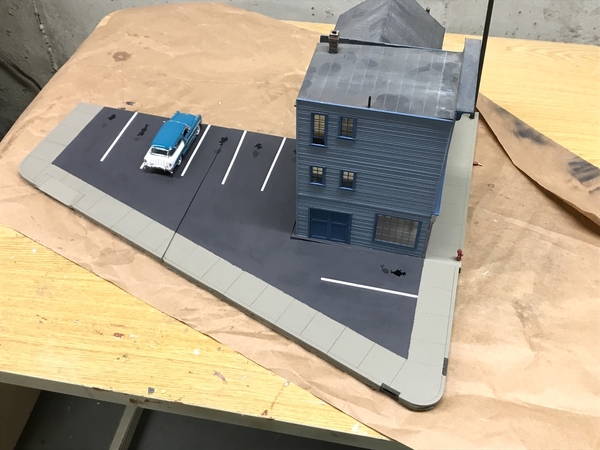
And here's the complete two-part base with the painted sidewalks. I will mask up to the sidewalk line and paint, mark the parking lines and paint white, then mask them and paint the asphalt. I made parking bumpers out 1/8" square strip wood. There's really not enough room for another building on this site so making a parking lot was in the municipal plan for some time. And it fills another empty patch of green foam.

Gravely New Base Sidewalk Paint

Started to work the new site for the House. Instead of using a ton of Sculptamold to fill in the back slope, I cut some foam core to fill the bulk of the space. I used 3M adhesive transfer tape to quickly and securely hold the three layers of foam core together. They were stair-stepped underneath to snug up to the slope. Notice I scribed and painted the four-scale-feet wide pavement on the street-sdie of the base. I also drilled the hole for the lighting wires and a corresponding one through the layout below.

HBTRR New Site Grade Filler

I wrapped the base plate with Press-N'seal to keep the Sculptamold plaster from getting all over the base, and making the base removable. I glued the foam sandwich to the layout using Liquid Nails construction adhesive.

While this was curing I started fitting the scale railroad tie retaining wall parts in place. Before the wall can be actually built, I will put a bed down of sculptamold so the ties will look like they're actually set in the dirt. I ran out of time for the plastering, but I did mix some raw sienna artists tube acrylic in the water I'm using for the plaster to pre-tint it. This way, if it gets chipped it doesn't show bright white plaster. I used railroad ties in the distillery building next door as well. It makes a realistic and reasonable retaining wall and let me extend the backyard a bit since as it was, the back steps wouldn't fit.

HBTRR Retaining Wall Planning

Attachments

Images (6)
  • Gravely Base Plate Ext Scribing
  • Gravely New Base Patch
  • Gravel New Base Ready for Paint
  • Gravely New Base Sidewalk Paint
  • HBTRR New Site Grade Filler
  • HBTRR Retaining Wall Planning

Excellent idea writing the book!  Turning on the lights is the challenge, especially with 'non-academic' kids.  My brother is a high school special education teacher.  His students aren't the ones with learning disabilities as we thought of special education growing up.  These kids are 'emotionally disabled' as they are known by.  He is retiring at the end of this crazy school year at age 62.  He has said cynically but with truth behind it that his job is to keep them from hurting each other until they turn 16 and drop out.  So sad.  A few years ago, a motorist turned a corner and into the side of his car.  Everyone was okay, but the policeman who showed up on the scene turned out to be one of his former students.  The young man was glad to see him and thanked him for his time teaching.  He said it was good to see one former student was making something of himself.

The scale tie retaining was is a great eyecatcher instead of making it look like concrete.  All towns these days need a parking lot or two.

Thanks guys! Mark, if you're amenable, I may send you the manuscript for your perusal. It's not too long.

Working two projects at the same time makes for a lot of pictures. Bear with me.

The parking lot sub-project is almost finished. I got all the painting done including the parking lines. I added strategic oil and trans-fluid stains. When this dries overnight I'll go back and add tire dirt, some tar strips and some pavement patches.

The concrete color I used on Gravely was a more green tint and it didn't match my newer shade and I didn't like it. I repainted Gravely's sidewalk to now match the continuation of said sidewalk on the parking lot. I started masking all the parking lines with strips of Tamiya tape cut to 3mm. I used dividers to space the lines and drew then sort-of square to the pavement edges. Only after I almost finished masking when I realized that I needed to paint the white first, then mask and finally paint the asphalt color. So I marked the tape's location with some pin pricks, pulled the tape and painted the white using some craft acrylic paint. I tend to use craft paints on structure projects since it dries dead flat and has pretty good coverage is cheaper than Tamiya. Here's after painting the white.

Gravely Parking Lot Lines Start

Instead of cutting more Tamiya tape to 3mm, I found some Tamiya Vinyl flexible masking tape in my tape draw that already was 3mm. I aligned the tape with the pin prick marks. You can just barely see the white tape on top of the white paint.

Gravely Lines Masked

With all the masking I was able to slather on a mix of Artist Tube Acrylic Mars Black and the same white craft paint. It mixes quite fine and the very flat white helped flatten the tube acrylic more. Once the black set up I pulled the tape. After it dried further I went back and touched up any leakage.
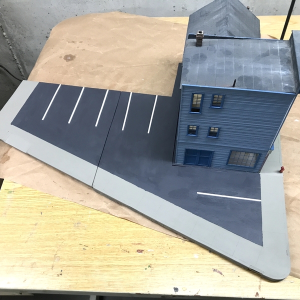
Gravely Asphalt Paint

And then I added the stains and used a pencil and straight edge to highlight the pavement groves. I also painted the storm drain inlets.
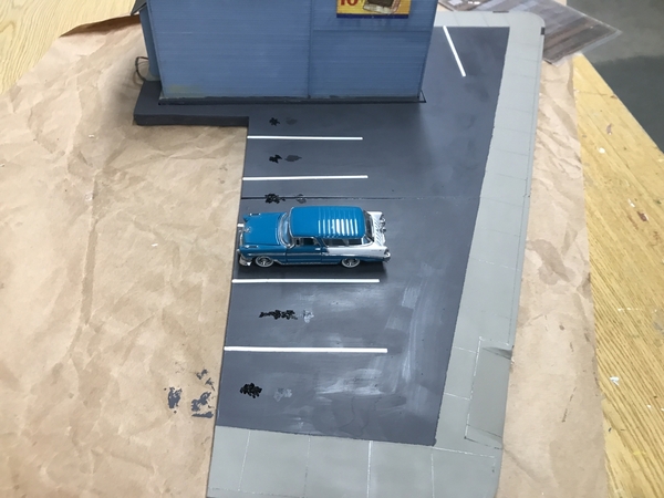
Gravely Lot almost doneGravely Oil Stains

After more weathering, this will be ready to drop back onto the layout tomorrow. I shouldn't have split the plate since it now has a seam that serves no purpose. It was originally split when the House was going on it so I could build the garage on a separate base without disturbing the House. When I changed the site, that "split" decision was moot. BTW: that was the last curb cut casting I had. It was the Sculpey master I used to make the plaster parts. I still have the mold. I could cast them out of resin also. I didn't resin cast when I made them originally. Or I could 3D print some…. Options, options, options.

Speaking of the House...

I got the sloppy stuff done today. I created all the grades with Sculptamold and embedded the first course of the RR Tie retaining wall into wet plaster so it will provide a realistic base for the wall.

As you can see I got the Sculptamold to a pretty good dirt color. When dry it will be lighter, but it won't be white. It still needs a coat of paint to glue all the ground cover in place. I also splurged and bought some complete floral pieces of Scenic Express. I normally don't do this, but I want it to have a garden with some color. This is a real focal point for the railroad and needs some special treatment. My mix might have been a little wet, but I was able to sculpt it reasonably well. I made it level with the Masonite baseplate.
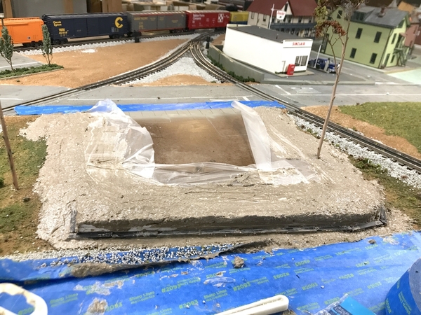
HBTRR STM Laid Down

Here's another view of the plaster as it was laid in.

HBTRR STM Laid Down 2

And a closer look at the base of the retaining wall.

HBTRR Enbedded RR Ties

I'm not a big fan of landscape work. It's a little too sloppy and imprecise for my sensibilities. It's funny since a young boy I would play in the dirt for hours and had some great earth moving machines to do the job. I kind of grew out of it.

When the plaster set up a bit so it wouldn't slump I pulled the baseplate. I didn't want it to be cemented in, since, as you'll see, I'm going to do more work on it.

This is from the inside-layout view.
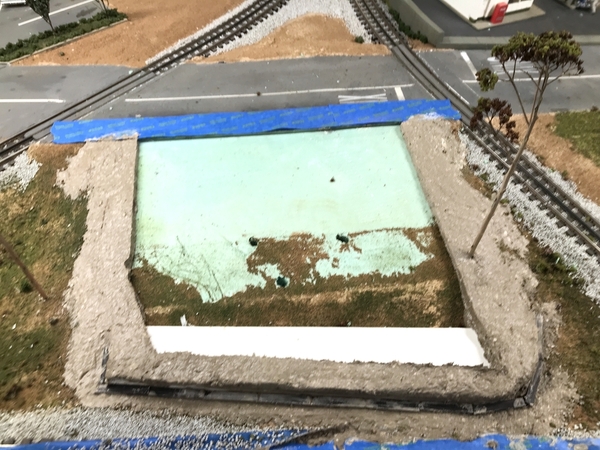
HBTRR Base Removed

And a view from the aisle.

HBTRR Base Removed Reverse View

After pulling the base I masked off the areas where the house will sit so I can use a thin layer of plaster so the house beds down a little. As I noted some time ago, the porch lattice and front steps are a little proud of the foundation. Having an 1/8" of plaster will let the house settle in and even out the mismatch. The house just sits inside the mask line.
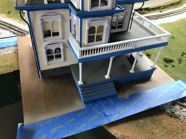
HBTRR Preparing Base 1

I will taper the plaster up to the mask, featheing it down to the edge. The edge matches the STM so I don't want to create a step. The house will be glued to the baseplate, but the baseplate WILL NOT be glued into its socket.
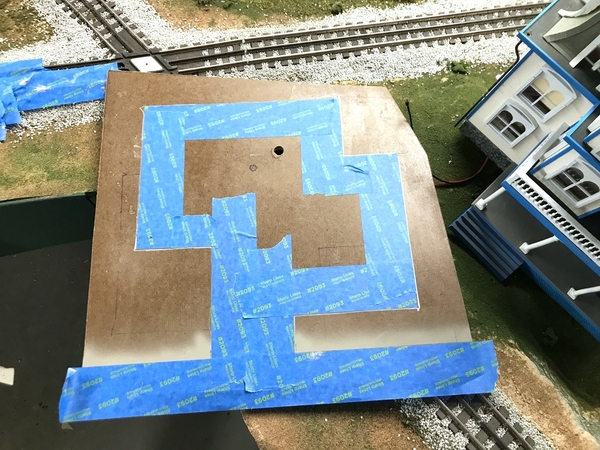
HBTRR Base Masked

I'll work on the baseplate tomorrow. STM takes a long time to fully cure. The plaster of paris sets in hours, but the fibers retain moisture for days. Before you paint it with latex paint to hold the ground cover, you need to have the STM fully dry. It takes patience. I don't think I'm going to use STM on the baseplate. I'll stay will basic plaster for a smoother finish.

Attachments

Images (12)
  • Gravely Parking Lot Lines Start
  • Gravely Lines Masked
  • Gravely Asphalt Paint
  • Gravely Lot almost done
  • Gravely Oil Stains
  • HBTRR STM Laid Down
  • HBTRR STM Laid Down 2
  • HBTRR Enbedded RR Ties
  • HBTRR Base Removed
  • HBTRR Base Removed Reverse View
  • HBTRR Preparing Base 1
  • HBTRR Base Masked

It's my acronym for Sculptamold which I find very difficult to type.

I have some more proofing to on the manuscript so bear with me.

I got the Gravely parking lot finished today. And I got a little work done on the House site, but then got completely waylaid watching insurrection taking place at our capital. I usually don't wax political in my post… philosophical.. occasionally, but rarely political. Today was awful. Our President continues to spew lies and incite people to seditious activity. Taking over the Senate chambers was inexcusable. Furthermore, if the complexion of the rioter's skin was different, the response would have probably been different too. It's very sad. I was so upset I had to have a shot of 18 year-old bourbon to steady my nerves and get my Afib heart under some control.

I got the Gravely building onto the layout, got its wiring re-attached and also installed those spiffy street lights. They have very fine, solid-conductor, lead wire. The hole for the poles is a rather small #35 drill and not big enough to pass my usual wire-connecting ferrules. So I had to run the wires below with their raw ends and then figure out how to terminate them later.

I added one asphalt patch and some tar lines. I made some parking bumpers out of some 3/32" strip wood, which I stuck to some tape and hand-painted them yellow and glued them to the lot with Aleen's. I sawed the with my new mini-cutoff saw, and sanded the tapered ends with the 1" belt sander. Ahhh… Power tools! Reminds me of Home Improvements and Tool Time.

Gravely Parking Bumper Paint

After gluing them in I climbed back onto the layout and put it all in place. Municipal improvements in action.

Gravely Parking Installed

After adding the lights and some light poles, the lot is effectively done. I used the term "effectively" because I've drawn and will be 3D printing (plus decals) some 21st Century parking ticket dispensing machines. These can be added later so it didn't affect the installation. And I have to terminate those light pole wires under the layout.

During my testing of the lights one of the poles accidentally touched the unprotected 12VDC and destroyed one of the LEDs. I was able to pull the bad LED out of the pole with its wires attached, remove it and solder one of my warm white surface mount LEDs and put it all back together.

Here's several views of the installation. I still have to paint asphalt the little filler piece at the street corner.

Gravely Parking Lot FinishedGravely Parking Lot Fin 2Gravely Parking Lot fin 3

I did get the retaining wall installed today using Aleen's. Having the first course solidly embedded in STM. It was very stable and made it fairly simple to glue the rest of the ties into the shape of the wall. I will got back and stain the cut ends and weather the ties to make it a little more old looking.

You can see by the color that some of the STM is fully dry, but the thick parts are not. Another day or two, this will all be done. I find things dry better in the basement in the winter than summer since I get a little bit of leakage from the HVAC so the basement is much warmer in the winter. I'll be adding some more filler (plaster to level the back yard. The side yards I'm going to leave more rough textured.

HBTRR Retaining Wall Installed

It's going to be a long night in DC and I hope tomorrow we get our democracy back. Interesting, Mike Pence called in the National Guard, not the President. Maybe it's time for the President to take his leave before more stuff falls apart. Meanwhile, due to the President's intervention in Georgia, McConnell has lost his majority leadership. Good going pres!

I promise, not more politics tomorrow. Hopefully.

Attachments

Images (6)
  • Gravely Parking Bumper Paint
  • Gravely Parking Installed
  • Gravely Parking Lot Finished
  • Gravely Parking Lot Fin 2
  • Gravely Parking Lot fin 3
  • HBTRR Retaining Wall Installed

Thanks Mark!

The first layer of Sculptamold (STM)  is dry and I decided that I'd just use it again to do a finish coat that would fill in the gaps and level the backyard. It's still a bit rough and I might put a skin coat on it to remove some of the irregularities.

HBTRR Site Final Filling

I also used STM on the House base. I realized that the fancy masking i did was unnecessary. I wanted the plaster to be under the House's edges so the house would embed in it. I pulled off the tape except for the small part from the sidewald up to the front steps. I then slathered on a layer of STM making it thickest at the house foundation edges and feathering out to the edges do it would still conform the plaster on the layout base. It will be dry tomorrow. This too might need a skin coat of regular plaster before the grass goes in. Consider all this as "rough grading" before the top soil goes down.

HBTRR House Embedding 2

The end is truly in sight.

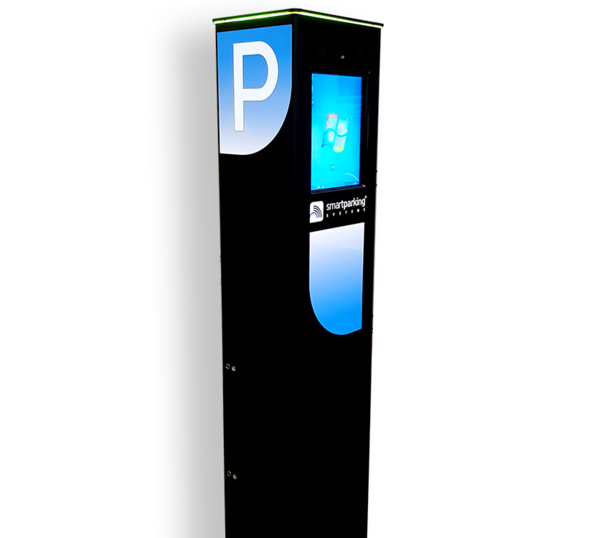
While the plaster was drying again I went back to some odds and ends. I found a modern park ticket kiosk on Google. I took some images from it and then drew my own in SketchUp and 3D printed the stand. I then used Corel PhotoPaint to edit the images and made some decals on white background decal film. The 3D printing went perfectly and they came off the Machine around 7:15. I cleaned them up and had them pose for some pictures.

IMG_8433

Here's the image from Google. I also used the side images which needed more fixing to remove the perspective.

Senza-titolo-12222222

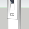
Here's the SU drawing I made. Notice that both images don't show the object all the way to the bottom. I had to take some license to finish it off.

Screen Shot 2021-01-07 at 7.52.31 PM

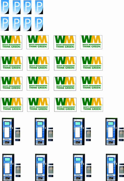
I couldn't use the face image as a flat decal since the keypad area is set in. Instead, I made separate decals for the key area so the model will also have the correct indentation. I know, I know, I'm nuts! Also on this sheet are the Waste Management decals for the dumpsters which I also got the green paint done today.

Accessory Decal Sets 1

To use the keypad decals I will cut out the blank portion of the decal before I soak it in water. Should be fun...

I had to mix my own green to get close to the Waste Management color. All my Tamiya colors were too dark. Plus the WM green had some blue in it. So the mix was mostly Tamiya dark green, a little bit of blue and then even less white. It's not perfect, but it's close. The green is darker than the image shows. Tomorrow I'll paint the black lids and put on the decals.

IMG_8432

And then I did one more thing. I'm trying to find the least uncomfortable way to electrify those Chinese light poles that I started installing yesterday. The problem is this. They don't have current limiters on them. They're just direct wired to the small LEDs in the head. So they needed LED drivers to keep them whole.  And this mean soldering them to the very frail light pole leads UNDER THE LAYOUT. I didn't want to do that.

What I needed was a little circuit board with ins and outs and the LED driver in between where I can just use a screw driver under the table to connect the series light poles to the LED driver. I have 10 poles needing powering and I can run three in a row in series. That would mean I would have to solder the splices together or contrive another way to go about tying them together.

I looked into buying some kind of ready-made circuit board, but didn't find exactly what I wanted and what I could make to work would have cost a ton of money. So I made my own. My first attempt was to use two strips of copper foil tape like a pseudo circuit board. I actually didn't need two strips as you'll see on my second attempt. I used one-half of my Euro-style connectors that are two-part affairs. I used these in long strips to make the panel separations of all the electric wiring on my first German iteration. This enabled me to take the panels apart maintaining all the wiring integrity when I took it all apart and moved it back to the USA. In this case I was just using the male component of the connector.

I started using stranded cable, but the close proximity made it hard to use and silly. But the idea was okay as you can see by the successful LED test.

Little Lighting Circuit

My second iteration made use of solid copper without insulation since nothing's going to touch anything. I drilled three small 0.022" holes for the CL2N3 drivers. This way I didn't have to trim the unused center tap and put the leads through the piece of MDF and crimping the leads underneath. I soldered the driver to the copper foil. I had contact problems on the small solder area in the driver. I will come up with a better way to solder it on my third iteration. I'm going to make five of these. Using the solid wire and strategically bent them AND flattened them to make them easier to solder. After shooting this image I soldered this one. If I made the copper angles a little longer I can solder them to the driver's leads and solve the surface area problem. The connectors are held with servo tape.

Little Lighting Circuit Ver 2

And I'm still not happy about yesterday and wonder how some many Republicans can still be fostering the myth about this election. It has the potential of ripping our country apart. The calls for the President's removal are growing. I dread what the next 13 days will bring. The big lie is still being told. Big lies bring violence, and yesterday it did.

Attachments

Images (10)
  • HBTRR Site Final Filling
  • HBTRR House Embedding 2
  • IMG_8433
  • Senza-titolo-1
  • 2222222
  • Screen Shot 2021-01-07 at 7.52.31 PM
  • Accessory Decal Sets 1
  • IMG_8432
  • Little Lighting Circuit
  • Little Lighting Circuit Ver 2

Yes, and wait and see how cool they are when they're finished.

Happy Friday! Whew… we actually made it through this crazy week.

First thing I did today was work to get the House baseplate to fit into the socket on the layout. It took about 20 minutes of cajoling and sanding with a Multi-tool to relieve the tight spots and get the plate to slip in. The arrow shows the area of most interference. When I was working on the Sikorsky, I bought the Harbor Freight Multi-tool. It's the middle priced unit and is noisy as heck. I used it for a while without my major jet muffs, but then put them on when I didn't want my ears ringing for the rest of the day. As it is I have tinnitus from my college rock band and working with engines in my early professional years.

HBTRR House Plate Fit Problem

It finally slipped in.

HBTRR House Plate Fit Right

And here's the reverse view.

HBTRR Plate Fit reverse view

With the plate finally fitting, I needed to improve the surface finish of the applied STM. I used DAP Spackle that goes on pink and turns white when dry. It worked as it should and filled most of the low spots so the grass will have a nicely graded topsoil on which to grow. Before I did this I had to figure out why the steps were sitting almost a scale foot above the base. It turns out that there was globs of plaster underneath the house and porch that was pushing the building upwards. I had to resort to chisels and putty knives to remove the errant plaster.

I applied spackle liberally to fill the House's base.

HBTRR Skin Coat on House Base

And then did the same for the layout portion of the base. I was wearing nitrile gloves and for the final step wet my fingers and smoothed the spackle to a final finish.
HBTRR Skin Coat Layout Base Rev

And again the reverse view.

HBTRR Skin Coat Layout Base


I brush painted the lids semi-gloss black and then got the decals applied. I still have to go back and use Dullcoat to seal the decals. Before applying the decals I brushed some Tamiya gloss on the green so the decals would bed down properly. They're pretty respectable little gems.

Dumpsters Done

After separating the park kiosks from their supports I sanded them, filled a few divots with Bondic and then painted them gloss black.

Park Machine Gloss Black

When they were dry I used some MicroScale Microsol to re-wet the surface and applied the park kiosk decals. It really came out as I wanted with the depressed area decals working well. When the decals are fully setup I'll glue one of these onto the new parting lot. The other will wait until I finish the parking lot that's going next to the Idaho Hotel. Reminds me of Joanie Mitchell's song, "They paved paradise and put up a parking lot". By using these parking kiosks, I'm relieved of the task of having to put parking meters on my streets. My streets are too narrow for street parking so there's that.

Park Machines Done

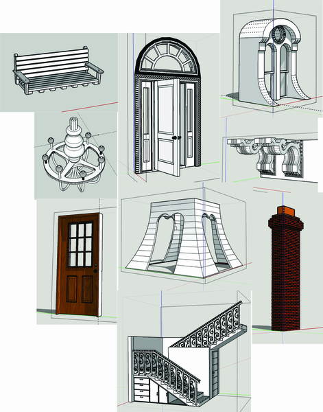
I've said this before, it still blows me away of how having some graphics software (and the skills to use it), access to the Internet and a 3D printer opens up the hobby to produce almost anything you want to make. It just takes the initiative to make it happen. The entire parking kiosk project probably took, maybe, two clock hours. It's really incredible. The House was a big deal which took tons of drawings and many hours of planning and printing. But the process enables small projects to be complete almost on a whim. Speaking of drawings, here's a sample of the drawing created for House. This is just a sample. There were more.

4-HBTRR Drawing Collage

Have a safe, healthy and non-violent weekend.

Attachments

Images (10)
  • HBTRR House Plate Fit Problem
  • HBTRR House Plate Fit Right
  • HBTRR Plate Fit reverse view
  • HBTRR Skin Coat on House Base
  • HBTRR Skin Coat Layout Base Rev
  • HBTRR Skin Coat Layout Base
  • Dumpsters Done
  • Park Machine Gloss Black
  • Park Machines Done
  • 4-HBTRR Drawing Collage

Well now you can pay for parking in my little town since the machine is installed. It's on the front right corner.

Gravely Park Machine Placed 1

And another view...

Gravely Park Machine Placed 2

I also placed the first WM Dumpster behind the appliance store after I gave it a coat of DullCoat to seal the decal. Probably should have some trash blown against the fence and maybe some debris around the dumpster where people missed...

Appliance Store Dumpster

As precise and finicky building the House, putting on ground cover is the exact opposite. It's sloppy, crude, rushed and very inprecise. I really see it as a necesary evil and I'm not very good at it. But regardless, it's very forgiving and things in nature aren't that precise in the first place.

The rushed part is the way the process works. I did the base under the house first and then did the socket on the layout. When I bring the two together I will add some more cover at the seam so the House will look like it part of the terrain. I used some medium tan house latex paint as the base coat. While it's really wet I sprinkle the various colors and textures of the ground cover. I used fine turf for the groomed grass and coarse turf elsewhere. When I said "rushed" it's becasue the latex starts drying quickly and stops being sticky enough to hold the material. I then used "wet water" (water, a few drops of dish detergent and some IPA) with a pippette dropper and then follow up with Woodland Scenics Scenic Cement also applied with a pippette. The problem I had was not matter how smoothly I laid down the ground cover, nor as gently as I added the droplettes, I still pushed the "grass" outwards that left little blank craters. The more you mess with it the worse it gets. So you keep wetting and adding more stuff until all the gaps are sort-of filled.

I have a hairpin fence that's going on the house boundary and I have some garden goodies (shown further down the page). I started to add undergrowth and bushes, but quickly realized that I had to wait for all the previously applied stuff to fully dry so I could use the heavier viscosity W-S Scenic Glue without messing up the grass. I'll do that tomorrow.

HBTRR House Ground Cover Begin

Here's another view.

HBTRR House Ground Cover Start Rt

The above was shot when there was still a lot of wet glue around.

I then did the same thing to the socket. I ran the ground cover into the existing terrain and feathered it so it won't look like it's just plopped there. I also vacuumed off all the debris and redid the track ballasting that was very disturbed during all this work. I have some more ballast work on the top right corner.

HBTRR Site Socket Ground Cover Rear

The aisle view shows some bare plaster on the very front edge of the grass. I will have to retouch those areas, leaning far over the layout and working backwards.

HBTRR Site Socket Ground Cover Aisle View

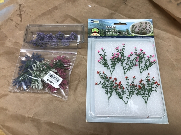
Like any construciton site with existing "old" trees, they can get disturbed and the one on the left is just about shot. I will have to cut it down and replace it. And my garden stuff came on Saturday. I bought some roses, forsythia and some lower bush violets. These will be the last ground cover that will be done. The roses seem a bit tall and I'm worried that I may need to make some trellises. We'll see how it works out.

HBTRR Garden Stuff

Attachments

Images (8)
  • Gravely Park Machine Placed 1
  • Gravely Park Machine Placed 2
  • Appliance Store Dumpster
  • HBTRR House Ground Cover Begin
  • HBTRR House Ground Cover Start Rt
  • HBTRR Site Socket Ground Cover Rear
  • HBTRR Site Socket Ground Cover Aisle View
  • HBTRR Garden Stuff

Mark, not so sure about the litter. I'm going to think about it. It will be a what-to-do-when-I-don't-think-there's-anything-more-to-do-on-the-layout project. Priority right now is getting the street lights in, and building another base plate for Idaho which needs to be settled in its new location. Then the Rick house… so that answers Pennsynut's question re: "What's next?"

I did make some trellises!

With SketchUp and a 3D printer, I took literally a few minutes to drew a trellis, and printed it. The print took all of 15 minutes. Took longer to clean it up than it did to print them. The design was very simple so drawing time was very quick.

HBTRR Trellis Design

Here are the printed parts during the cleaning process.

HBTRR 3D Printed Trellises

I simply stuck them into some floral foam and shot them with Krylon Gloss White and they were done.

HBTRR Trellises Painted

I had trimmed some dried Oak Leaf Hydrangia blossoms a couple of years ago thinking I was going to turn them into trees. They had a pretty good shape and could either be deciduous or evergreen. I was discouraged since I thought I have to remove all the little un-opened blossoms before flocking them, so they just sat on a box on the floor. I was going to throw them out in my cleaning spree, but after looking at their shape again, didn't toss them. Then today I realized that those un-opened blossoms would serve as more surface area to glue the flocking.

I had to clip the dried actual blossoms, but left all the un-opened ones. I then sprayed them with the 3M-99 and dipped the branch into a pile of medium and dark green coarse turf and the results were pretty decent. Of the pile of branches that I have, most had a pretty severe bend in the top branches, so I didn't use them. The bush has a bunch more dead blossoms and I'm going to collect them. They have a good branching structure that's better than the W-S plastic trees, AND THEIR FREE.

HBTRR Oak Leaf Hydrangia Tree

The other one is smaller so I put it near the other existing tree. Incendetally, I simply pulled the old tree out and inserted the new big tree in the same hole.

HBTRR Little Oak Leaf Hyd Tree

With yesterday's ground cover nice and dry and I added all the garden flowers. I laid down a glob of W-S Scenic Glue and placed the plants in nice places. Then I went around the two sides and placed W-S undergrowth in alternating colors around the foundation.

HBTRR Garden Plantings

It was time for the roses. I used a #53 drill and pin vise to drill two holes; one for the trellis and ther other for the roses. Another blob of glue and they were in. I needed my phone light to see the holes through the ground cover that wanted to fall back into the holes.

HBTRR Garden Complete

I placed the house back into the socket to take a status shot, but it's not fitting quite right and I'll have to remove it tomorrow and do a little more shaving. Some of the spackle found its way into the socket tightening up the fit a tiny bit.

HBTRR Final Fit Test

When it's fully seated it's going to look really good.

I painted the laser-cut hairpin fencing while still in its fret. I airbrushed it with gloss black.

HBTRR Hairpin Fence Paint

After clipping them out of the fret, I made a dilling jig to simplify the field work.

HBTRR Hairpin Drill Jig

This is why I had the #53 drill in the pin vise. It the clearance hole for the fence posts. Here's the pile ready to install tomorrow. The distance from the steps to the left edge is exactly two fence sections. I don't know that the length is going towards the right. I don't think I have enough fencing to do the entire perimeter. If not, I'll just run down the sides, but leave the back open.

HBTRR Hairpin Fencing

I'll fit the fence tomorrow when the House is off the layout. I'll have to be careful putting it back in the socket, which is another reason why I need more slop in the socket. I don't want to force anything. Once it's finally in the socket, I clean up the joint gap, hook up the lighting power underneath and the HOUSE PROJECT WILL BE DONE.

The folks living in the House by the Railroad, really better like trains. There are tracks to the right, back and front. That's some serious train traffic.

Attachments

Images (11)
  • HBTRR Trellis Design
  • HBTRR 3D Printed Trellises
  • HBTRR Trellises Painted
  • HBTRR Oak Leaf Hydrangia Tree
  • HBTRR Little Oak Leaf Hyd Tree
  • HBTRR Garden Plantings
  • HBTRR Garden Complete
  • HBTRR Final Fit Test
  • HBTRR Hairpin Fence Paint
  • HBTRR  Hairpin Drill Jig
  • HBTRR Hairpin Fencing
Last edited by Trainman2001

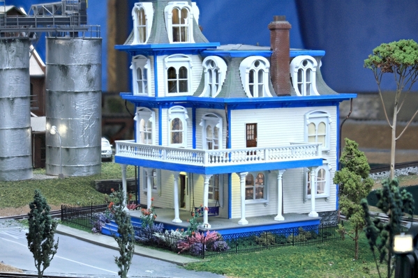
You may perform the drum roll for real, for as of today, the House by the Railroad project is complete. My original project plan had completion on January 6. I'm exactly one week late. The new owners will be gracious and accept their house. The power was turned on today so they got their CofO.

Before the house could be turned over to the owners I had to finish up the fence installation, clean up the landscaping, fit the base into the socket and then landscape the joint. All was completed.

The trickiest part of fence installation was connecting it at the corners. Since this was laser-cut out of laser board it was effectively a two dimensional affair. This left the corners very insubstantial with effectively no gluing surface. I had to thicken the corners and create and end post since the sections had an end-post on one end, but none on the other. I used some thin strip stock which I doubled, used med CA to glue together and then re-shaped the mounting tab so it conformed to my #53 drilled holes. After assembling the fence I re-painted all this gloss black.

HBTRR End Fence Post

This was what the corner post looked like prior to touch up painting. The flowers had to protrude through the fencing, which took some careful manipulation with a tweezers to coax them through the fence bars.

HBTRR Hairpin Corner Post

After installing all the fencing which I had (as I noted yesterday, there was enough for the perimeter) I went back and touched up the landscaping at the edges in preparation for reinserting into its socket.

Here's a shot with all then fencing installed and re-painted. I did this work in the shop on my normal workbench.

HBTRR Hairpin Fence Installed

I had to shave some spackle out of the socket area and sanded the house base to taper it a bit from the bottom layer upward so it fit more easily. It dropped in! Then I had to fill the gaps. I think I erred here. Some of the scenic cement got into the joint and it will effectively glue the house base into the socket making future removal difficult. I'll worry about that when I have to worry about that. Since the lights went on perfectly, and none of the furniture or people broke loose in all the manhandling, I won't have to pull it up for a long time. Probably when I'm gone and my wife or kids want to sell it all off.
So let's start with the only final rear view I made with the iPhone. I made most of the final pictures with my Canon using Zerene Stacker Depth-of-Field enhancement software. I added the steps which crosses over the socket gap. I also re-touched the RR tie retaining wall. The seam is effectively hidden on this view. I carefully added the scenic cement and sprinkled the ground cover, held with wet water and scenic cement to lock it all in.

House Final Rear View

Notice that the fence ends 3/4 the way back on the sides. I bought this fencing from River Leaf Models and I don't think Andre Garcia is currently running that business.

Now for the finished front shots.

House Final Rt FrtHouse Final Lft SideHouse Final Frt RtHouse Final Frontal

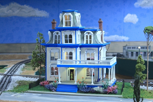
I don't know about you, but it came out looking exactly as I foresaw it in my mind's eye. I wanted a garden in front, and there's a garden. I wanted an interior and you can see it from the front, and from the rear you can get really close. You can't see the dining room from the rear since you're looking at the kitchen, but you can see it from the front. It was singularly the most complex scratch-build project I've ever attempted. It all started being able to draw those Mansard windows. It couldn't have been donw without 3D capablility... a ton of 3D printing. The interior was a whim that was a load of fun. It's heavy and miraculously, I didn't break anything in all the moves I had to make to get it done. It was a real breakthrough by getting out of my box and re-siting the House where the Idaho Hotel was sitting. This building is sooooo much more dramatic than Idaho that it deserved to be showcased where you can view it unobstructed.

I'm expecting that this will be an upcoming article in Railroad Model Craftsman magazine. No publication date has been given and it could be 2022.

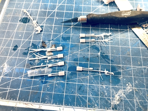
Thank you all for following along. My next project will be the Bradley with BUSK (a plastic kit project). Meanwhile I printed a ton of tiny angle brackets in preparation for the Rick House. I had to use the micro-razor saw to remove the brackets from their support posts. It was tedious and, since I don't need them for a couple of months, I stopped work on them. I printed two batches which should be enough for the structure. I'm only going to use them on the floor joists near the edges where they can actually be seen. The ones buried within the structure would be a waste of time and effort. In some prints the two nut/washers didn't totally print. They'll work!

RH Support Bracket Print

Attachments

Images (9)
  • HBTRR End Fence Post
  • HBTRR Hairpin Corner Post
  • HBTRR Hairpin Fence Installed
  • House Final Rear View
  • House Final Rt Frt
  • House Final Lft Side
  • House Final Frt Rt
  • House Final Frontal
  • RH Support Bracket Print

Many thanks loyal followers!

While I have the Bradley to start, I'm kind of fired up and ready to go in getting more of the town finished, especially now that Idaho Hotel is sitting on bare green foam. I'd like to get rid of all the bare foam in the next few weeks (except for where the rick house will go). Today, in a short session, I got the baseplate for Idaho and its associated parking lot next door cut out of Masonite. In the next series of seven images I'm giving a terse description of how I go about this.

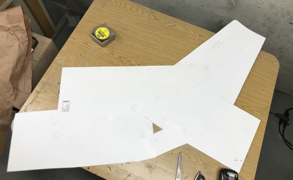
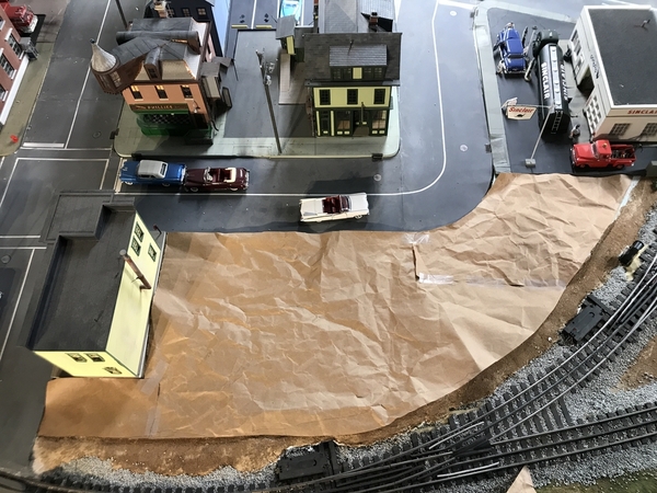
The site in question was quite irregular so to minimize wasting valuable material I started by making a rough template using kraft paper that came in some delivery or another. "Waste not want not." To find out where the curves fell I just creased the paper and drew the pencil around that shape.

Idaho Making a Base Step 1

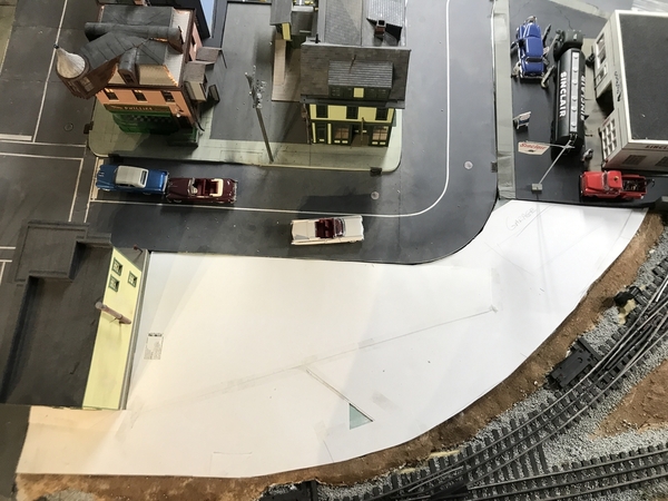
I didn't have much light weight Strathmore paper but had some chunks that I was able to tape together to make a piece big enough to create a full-sized template. I wanted a more substantial material to be able to trace the design on Masonite.

Idaho Making a Base Step 2

I traced the kraft paper template onto the strathmore version. I then cut it out and tried it in the space.

Idaho Making a Base Step 3

It was time to locate the Hotel onto the side. I wanted an alleyway between Saulena's and the Idaho, and also wanted to keep Saulena's sidewalk width consistent in front of the holel. The red lines are Idaho's footprint. (added digitally). Based on it's orientation, all the parking will be on the right side. I notice that there's not much room for traffic to get behind from the parking lot. That means I need another curb cut behind Saulena's I'm putting another dumpster back there.

Idaho Making a Base Step 4

When satisfied with the fit, I tape this more-substantial template to the Masonite. I didn't have a single piece of Masonite to create it in one piece.

Idaho Making a Base Step 6

I then taped the two pieces of Masonite together and taped the template to them, and then marked where the added piece would be cut. I used the Saber saw with a fine toothed blade to do all the cutting. It makes a heck of a racket, and I wear my big 3M sound killing ear muffs. Unfortunately, that didn't help my wife upstairs while trying to read. It wasn't a long cutting session.

Idaho Making a Base Step 7

Attachments

Images (6)
  • Idaho Making a Base Step 1
  • Idaho Making a Base Step 2
  • Idaho Making a Base Step 3
  • Idaho Making a Base Step 4
  • Idaho Making a Base Step 6
  • Idaho Making a Base Step 7

She also hears a lot of good music since my iPod with it's 3,000 songs is playing continuously and I'm either singing or whistling along.

I was going to use the foam core to space upward the Masonite base for Idaho, but I don't have much more than scraps floating around the shop and didn't want to go to the store for it. I needed to make the total thickness exactly 1/2" since this the the pavement height to the lower base of Saulena's and Idaho needed to match that. The two layers of foam core plus the Masonite, don't actually measure that. But there was something else I had that could work. It took me 20 minutes to find them.

If you were all paying attention during the Engine House build, you may remember that I had ordered double the number of pilaster stock. I was thinking I needed to double them up and Rail Scale could only cut 1/8" MDF. I had taped all this surplus and stuffed it in a box. Being the Masonite and the MDF were all 1/8", 3 slats glued together and then glued to the Masonite gave me my 1/2".

I used the 3M 90 contact spray and laminated them together. I then strategically glued them to the underside of the Masonite base. Of course I started gluing them wrong. I was rushing as usual. First I started gluing four pieces together thinking that made 1/2", but I forgot that the Masonite is part of the stack. Then I was gluing them on the top side of base. Luckily, the glue hadn't really set up and I was able to break the joints and get it right.

I had enough MDF to do the entire job. For the rail facing edge, I didn't need to form a smooth, filled edge and it was curved. So I just backed it away from the edge and used a series of straight segments. You can see these at the top of the piece. As you can see, I didn't need to have a solid layer of filler to raise the Masonite. I just needed enough to evenly raise the whole deal.

Idaho Base Spacers Install

For the street facing edges, I had to try and make the edge as much as possible. This will form the actual curb and I don't want to laminate anything on top of it. Most of the street-facing edge is straight and then there's that curve.

I made a card template of the curve and cut the first piece of the laminate on the scroll saw.

Idaho Base Fitting curb curve

I then marked and cut the last piece of the puzzle for that remaining wedge piece. There will be some minor areas to fill, but most of the curb will be MDF/Masonite laminate. You can see this last piece under the clamp. Even though 3M 90 is a contact cement, the joints were stronger if I clamped them during curing. It cures fast. You can see a few of the areas requiring filling in the image below.

Idaho Base Last Curve piece

I cut some laminates to fit in the smaller places. There are some straight sections light the part above the clamp that will need final trimming.

Idaho Base Spacer Fitting

I still have a few more strips left over and I'll probably find a use for them. It keeps reinforcing the mantra, "don't throw anything out, you may need it sometime."

Idaho Base EH Surplus

I marked out the Idaho location on the actual Masonite and there is enough room around the back corner to pass a vehicle. Since I needed more curb cuts I decided to draw one and print it. Again, the drawing took 15 minutes and the printer's working downstairs while I'm writing all this.

Screen Shot 2021-01-15 at 7.35.02 PM

I hollowed out the bottom and put some ribs in it to help prevent warping. And because of this I had to place it in the machine on a bias extending the print time to 6 hours. No problem. It was printing when I was doing something else. Multi-tasking.

I've notice something I don't like with that mini-chop saw. There's no back stop for the cut part. When the saw makes the final cut the part is flung back into the saw with some force… enough to actually damage the part. A real chop saw has a fence on both sides of the cutting path so the cut parts are not flung away. If I cut very slowly near the end and keep the saw speed up, I can minimize it, but it's a design flaw. When cutting small strip wood it's no big deal. Cutting the 3/4" wide MDF was a different story.

Attachments

Images (6)
  • Idaho Base Spacers Install
  • Idaho Base Fitting curb curve
  • Idaho Base Last Curve piece
  • Idaho Base Spacer Fitting
  • Idaho Base EH Surplus
  • Screen Shot 2021-01-15 at 7.35.02 PM

Add Reply

Post

OGR Publishing, Inc., 1310 Eastside Centre Ct, Suite 6, Mountain Home, AR 72653
800-980-OGRR (6477)
www.ogaugerr.com

×
×
×
×
Link copied to your clipboard.
×
×