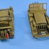
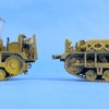
Yes you will rise to the challenge!
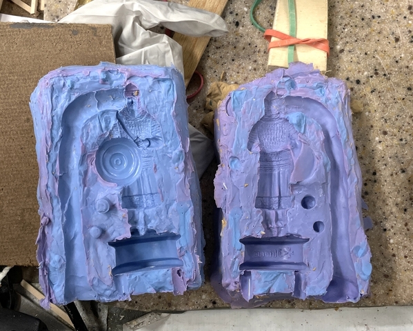
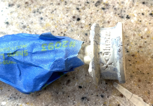
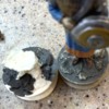
I forgot to post a picture of the open mold. I really don't understand the color shift between the bottom and top mold halves. I thought I was using the exact same proportions of blue and pink, but the mix doesn't lie. The second batch clearly is heavier in the pink. It cured fine and worked. As you can see in the mold, there was some transference where the top mold stuck to the bottom as a result of no mold release coating in place. I was still able to rip it open… thankfully. The mold is not pretty, but it was effective. Anywhere you see lavender on the left mold and blue on the right is an area where the new silicone bonded to the older. It should happen that way. The mold proper did not leak and the product is pretty flash free. There were a lot more alignment lugs that glued themselves together and got torn apart when I opened the mold. Next time: DON'T FORGET THE MOLD RELEASE!!!
Attachments
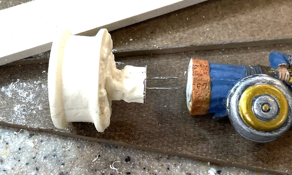
Having the ability to mold more than one piece let me produce enough so I could practice on the cutting and binding of the new base to the old figure. I did decide make the cut at the tunic bottom and glad I practiced since it helped me understand how much material was removed in the razor saw's kerf. I use the points clipped of some T-pins to locate the corresponding point on the other part so my drilling would be reasonably accurate.
I was able to build the test which took a little fussing to get the alignment close. When I thought I figured it out I cut and drilled the real parts.
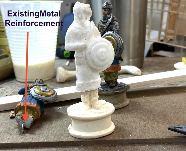
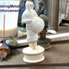
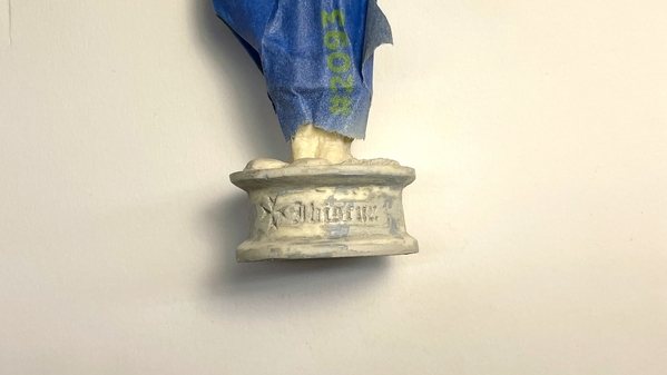
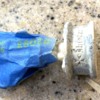
This picture, which actually preceded the above, shows the metal reinforcement that ran inside the original figures. Of course the base broke off just below where the metal rod ended.
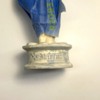
I used a small starter drill to open up the pin pricks and then opened to 1/16" where I then used some brass tubing of the same size to pin them together. I used epoxy to make the joint fast. Making the joint at the tunic bottom was the right place since the junction will be invisible when I'm done. Epoxy cured and the piece is solid. The picture makes the rebuilt one look shorter, but it's really very close to the same height.
Now the fun begins with matching the paint. Again, I'm going to use my test pieces to perfect it before attempting to do the actual piece. I am pleased how the cast bottom worked out.
Attachments
Multitasking day...
Started working to develop the color palette for the Chess Piece. It took five tries to nail the color of the base's rocky upper surface. It turned out to be a lighten NATO Back with a hint of Khaki… a greenish dark black gray. I started painting color samples on the lower left and went around clockwise to the one that's close enough. I don't know how old these figures are so I don't know how much fading there is. They can't be too old since they were cast resin of some variety or another.
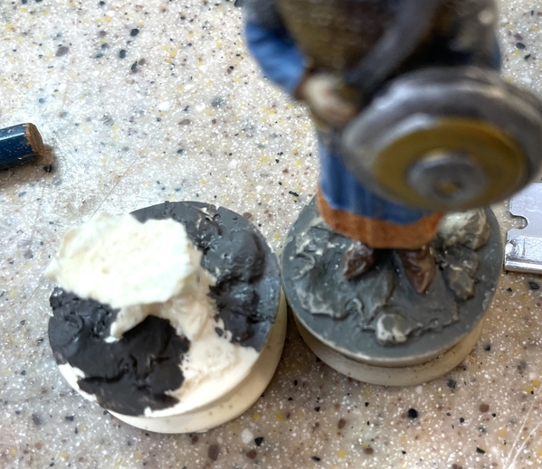
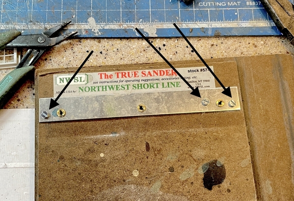
Color matching the base color proved much more elusive. It turns out to be a light gray tan with a hint of red. Luckily I had all of those extra bases upon which to experiment. I masked the upper part of the figure and airbrushed the base color. When it dried I noticed a lot of pin holes (small air bubbles) so I went around and filled all the imperfections with Tamiya Fine Putty. When dry I sanded it with the power mini-sander.
The color appears very light, but it will get treated with an aging wash using Tamiya Accent Liquid. Again, I may add some brown to the black to warm it up a bit. The filler looks bad, but it's not.
After sanding here's what it looks like. Tomorrow, I'll mix another batch of base color and air brush it again. The white balance is way off in this picture. It's sitting on a pure white piece of Bristol Board and I shoved the white balance as far to the blue as possible. My shop light over the work bench is a warm CFL that's very yellow. I'm confident that the base color is going to work.
Attachments
It’s looking quite nice
Thanks Mark!
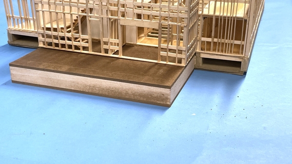
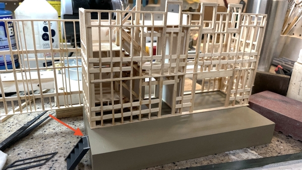
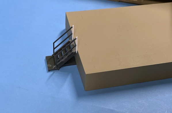
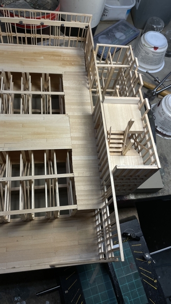
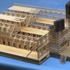
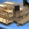
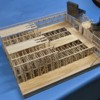
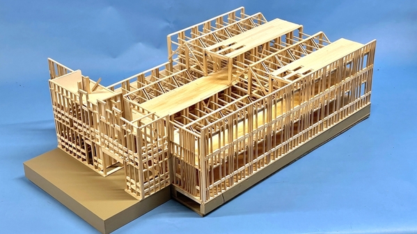
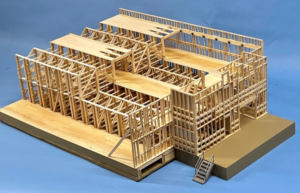
Exercise and errands gave me something less than an hour in the shop. Did two things. Got the Rick House loading dock 'sandwich' glued up and partially sanded. It needs filling and sealing and then painting the same concrete color used for the RH foundation. The dock is not glued to the building in this image. I will also install a bumping strip to the top dock edge and a metal (Plastruct) stair down the left side.
I also got the chess piece base paint done. It took a lot of fussing again to get a reasonable color match. It was made more difficult because of the weathering glaze on the original. I had to peer through the glaze and imagine what the actual color looked like. It's a bit of white, buff, red, yellow, black, etc. Again, I relied on the other base piece I molded so I didn't have to put any extra paint on the real one. I also did some more final sanding on the filler in prep for the painting. I'm going to practice on the spares to do the weathering too. I also added a coating of Dullcoat on the rock portion so that color coat won't bleed the base color that's also on the rocks. Tomorrow I'll do the rocks, then match the pants and boot colors. Once all the color coats are on, I will do the weathering. My goal is that you won't readily be able to tell the difference.
Attachments
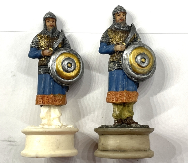
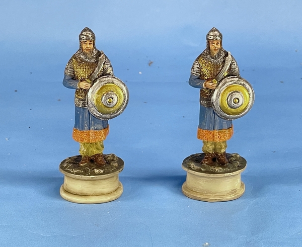
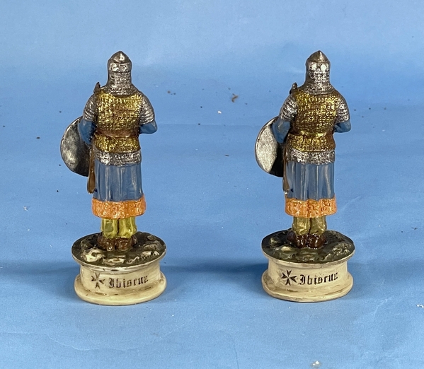
The chess piece is done and shipped… and I was paid already. I sent the client these images and she was beyond happy. I had my wife and son in law and they couldn't identify which was which. 'Is it real or is it Memorex?' Remember that. I am pleased with how it came out. It was a challenge.
Gone on a road trip tomorrow. Will be back on Monday. Have a nice weekend!
Attachments
Looks great! Have a safe trip!
Great job, Myles. I can't tell the difference.
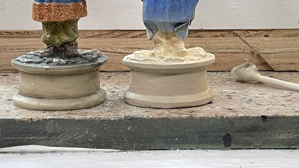
Okay. I’ll tell you the answer. The original’s on the left. The one I restored has the glossier shoes. I couldn’t get the shoes to flatten out. I even shot them with Dullcoat. It’s good. If they were the same luster as the original I couldn’t tell which one either.
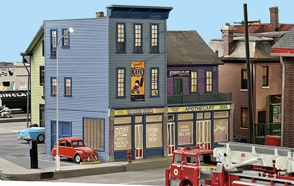
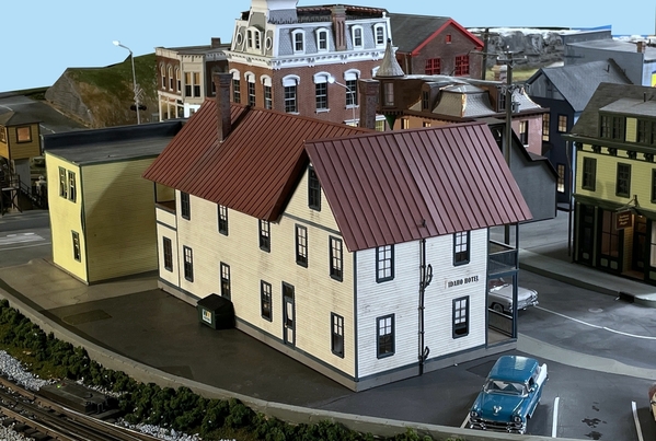
\\\\I'm thinking…. I know, I know… that's dangerous … that I probably should sell off some of my kit buildings to make room in town for more custom designed and built models that I'm doing. For starters I'm thinking of selling the Bar Mills Idaho Hotel and Gravely Building. I don't know how much to ask. Both kits were purchased for $170.00. What should a built-up price be?
Attachments
Myles, I think you have probably hit on a good idea since you are running out of real estate. I have no idea what is a reasonable built-up price. Maybe I could come up with a ballpark figure once I go back and review your documentation of building each.
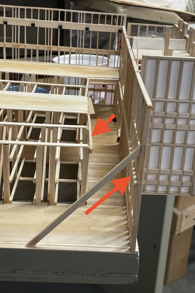
I did do work since the last post, but didn't post yesterday. The stairway and loading dock are complete. The loading dock needs some more detail work with the access stair and the bumper strip on its face. I will also weather it a little, although it's new concrete. I got all the stair handrails in except for one inside rail that I just couldn't reach. Can't reach and can't really see.
I got all the stairs and landings fit and put some ledges under the big landings after marking where the joist fell on the walls and framing.
After getting the first to second floor stairs and landing glued in place I put in the outside railings on both flights. I made some standoffs for these railings which was an overkill detail.
I finish sanded the loading dock and took it outside to put the concrete color on (Rust O-leum Camouflage Tan).
I then glued in the second to third floor stairs and landings. When they were set I installed the 8 X 8 vertical columns that support the center of the stairs and providing a place for the inside railings. These did not get standoffs. In this picture you can also see the piece of Plastruct stair that's going to be the access stair to the loading dock. The Plastruct railing is too long so I'm going to scratch-build railings out of Evergreen styrene angle stock.
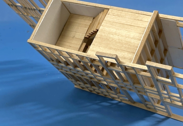
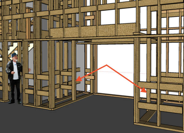
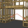
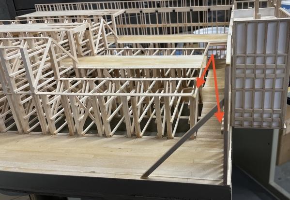
Next up is some more internal framing inside the elevator shaft. There is some cribbing that lines the shaft and ties back to the building structure. There are sole plates that tie these columns to the bottom so I can build this without gluing the front onto the loading dock. It would give me easier access. Arrows point out this framing.
Attachments
Mighty fine work on the whole project.
Thanks Mark!
Bought some more bridal tulle today to make the chain link construction fence around the rick house site. It's the CHEAPEST HOBBY PURCHASE EVER! 19 cents for a 54" X 4" piece enough for that fence and more. The fence will be a scale 8 foot (2"), so I should be able to get 108" running inches of fencing or thereabouts.
I built the access steps. My idea to use Evergreen for a new railing didn't work out as I would have liked so I trimmed the Plastruct railing and added a small piece of Evergreen to finish it off. My solvent cement (MEK) was not fusing the styrene to Plastruct's ABS as it should. I used med CA to glue the styrene strip to the ABS to finish the rail. I mounted the steps on some larger Plastruct ABS Channel. I will spray it metallic next week.
I started and almost finished adding the elevator shaft bracing. The first part didn't come out so square, the rest are okay. I was using a combination of med CA and Bondic UV to hold it. Aleen's just isn't good when the pieces have the ability to move all over the place. The Bondic freezes them in position in five seconds and I follow up with CA and accelerator.
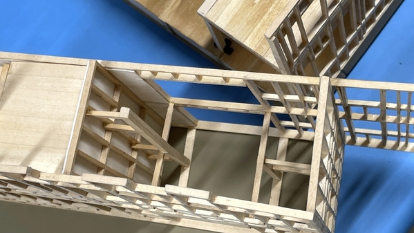
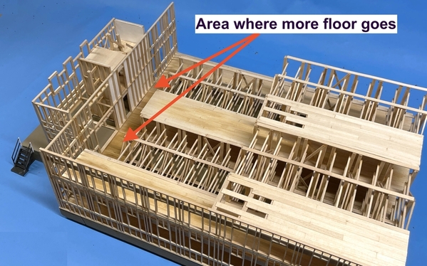
This next shot shows just what's left in the flooring department to finish it up.
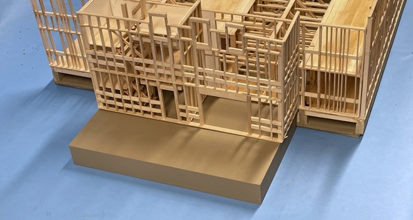
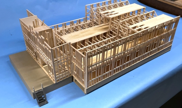
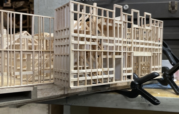
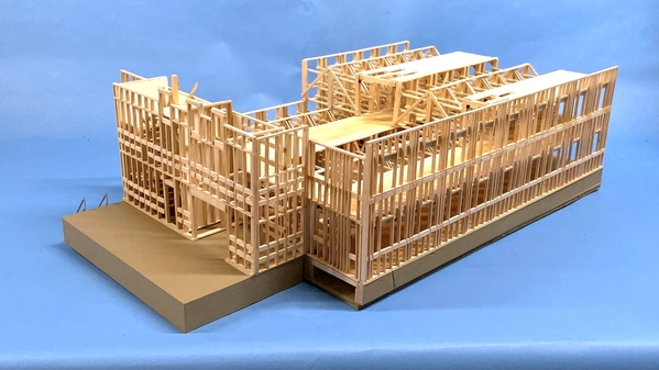
And then I took a picture just because I wanted to. The front is still not attached to either the framing or the loading dock.
The is an overhanging roof protecting the loading dock. I can't decide if I want to add it. It will look cool, but it will hide a lot of the stair well stuff inside. Thoughts?
Boy! That's a lot of lumber!
Attachments
Myles,
it would be a shame to hide a lot of the stairs you worked so hard building.
I hear you Mark. I'm leaving off the canopy.
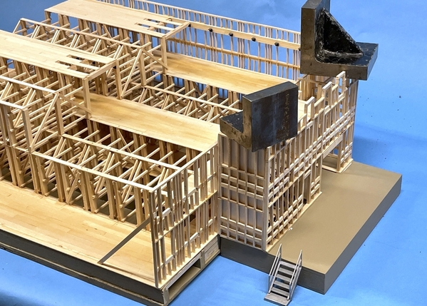
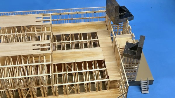
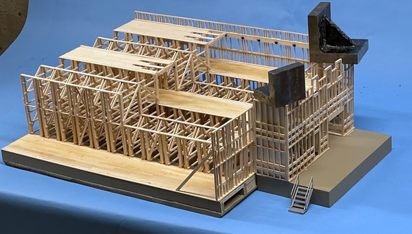
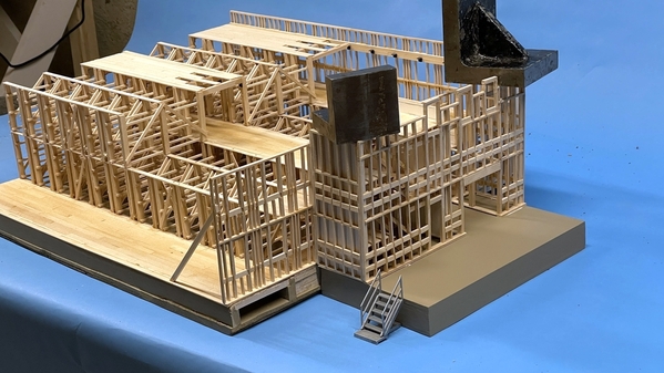
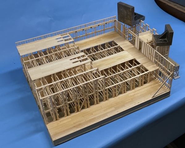
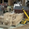
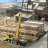
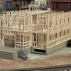
Got a lot done today. I finished the last elevator framing, glued the front to the rest of the structure, finished the flooring and mounted the loading dock. Took more status pictures.
I had to add ledges to both sides of the front flooring areas. I used a surface gauge to get the correct height and transfer this to the front wall. I glued the front ledges on while the front was still separate from the building. I also added addition ledges for the ends of the ricks. I realize I hadn't designed this as well as I could since I wasn't sure about how much floor I was going to install until the building was nearly finished. If I build another it will be a different experience.
Also before gluing on the front I added another layer of sole plates to the front lower edge so it would more perfectly match the loading dock height. After these two add-ons I glued on the front using Aleen's. I added some strategic spring clamps to hold until it set.
To ensure that the front was plumb, I used a angle block and secured the left end with a brace that was pinned to the base. For this I used CA and accelerator to glue it. The arrows are pointing out the floor ledges, but the next image shows them more clearly.
This view shows the ledges more clearly.
Because my ricks are not completely parallel with the base, I had to hand-cut each floor board since they varied in length quite a bit. Even so, I did all the flooring in about an hour. One of the changes I would make would be to interlace the new flooring with the existing.
Lastly, I glued the loading dock to the building. Before any of this, I made sure the front face of the foundation was reasonably flat to accept the loading dock. To get the glue to set nicely I used gravity clamps. Also not that I painted the outside stairs with Tamiya rattle can Real Metal, which looks pretty much like galvanized steel.
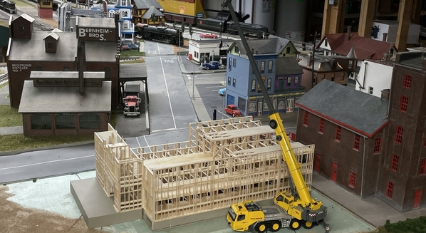
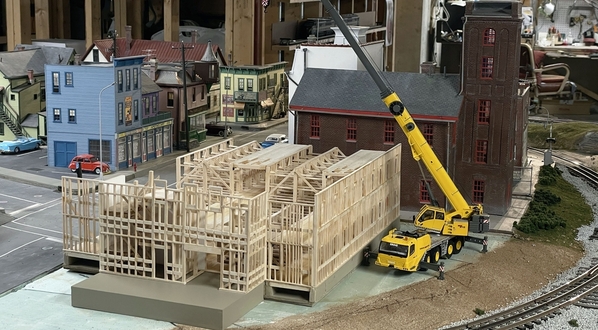
Here's a few more views of the almost-finished Rick House. The clamps come off tomorrow and then I'll try it on in the layout. Next up: Site completion.
To sum up, the build so far has been 3 month elapsed time not counting the ridiculous amount of hours drawing it in SketchUp.
Attachments
Attachments
Looks great. Can't wait to see it in place.
Looks fantastic, Myles. I know I'm a little late with my comment but another option for the canopy is to add a canopy that is under construction. That would show that there will be a canopy and still allow visibility of the stairs.
Myles
Great looking detailed model.
You might want to add scaffolding around it. Given what you have done so far a scaffold would be trivial!
It certainly looks great, Myles!
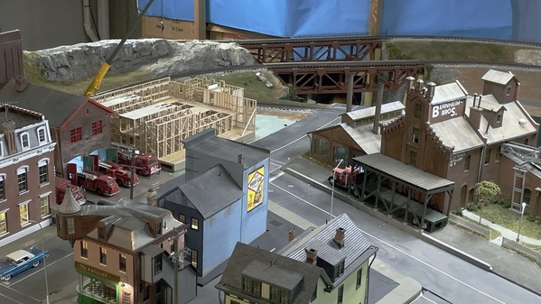
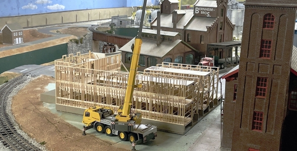
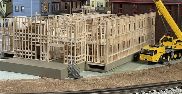
Thanks all! I plopped it on the layout in its spot. It does fit and when I regrade the slope to the track to flatten it, I'll pick up some more flat land. There's even a little room for the big Grove crane. Regarding canopy under construction… Not a bad idea and I'll work on it. Regarding the scaffolding, I don't know if there's enough room for it. There doesn't appear to be scaffolding around the actual sites, but I'll check. I appreciate the offer. I still have to do ground cover, chain link security fencing and lighting, and a nice sign telling the good folks of Woodbourne that Bernheim Distilleries is building a new bourbon warehouse. That should all be done in a week or two.
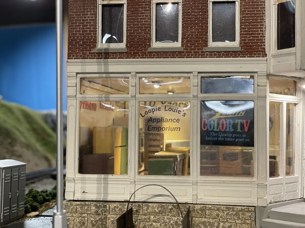
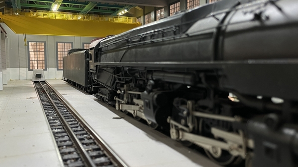
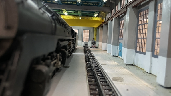
I also had some fun today with the feature that lets me take pictures with my iPhone 12 Pro using my Apple Watch's camera feature. So I took some closeup shots of some of the building from street level.
That Pennsy Q2 is one looooonnnnng engine. Wide angle lens exaggerates the length even more. The phone was actually into the engine house. Couldn't have done this shot without the remote actuation. I still have to build the work platforms for the outer edges of the outside tracks; another small multi-media project. The camera position in these images is just a little above a 1:48 person's eye level.
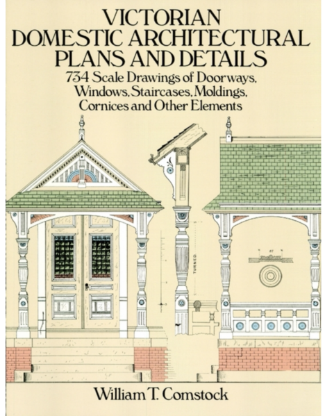
And, based on some input from a Facebook site I'm currently visiting, I purchased two book, both originally written in the 1880s, on actual Victorian architecture with detailed drawings of floor plans and all the nifty little details and another on color schemes of Victorian houses.
Armed with these books and my 3D printer, my crazy Victorian building spree can go to the next level. It will be much easier to design and build the structure with drawing of real parts with real dimensions instead of estimating from one or two pictures.
Attachments
Well, I finally know what a rick house is now. When I was restoring victorian houses in real life I had that book and
several others.
John
Myles, The rick house and crane really look great on site. Once you have the grounds and fence in, it will be a real show of progress in your town!
All the other photographs look wonderful as well!!
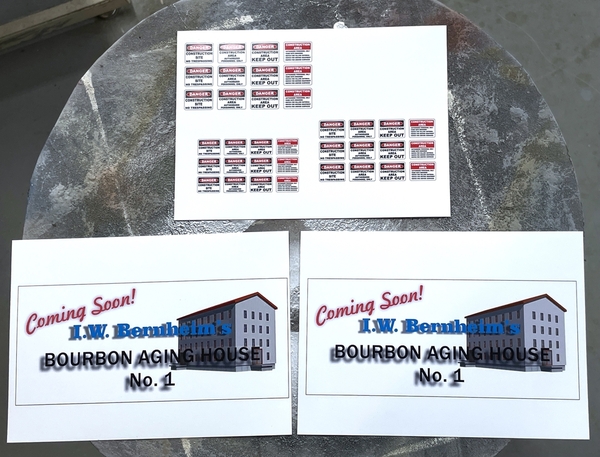
Thanks! It's going to be a real hoot seeing how much I can create in 3D using real Victorian references. I ordered the additional brass tubing for more chain link fencing. I will need 96 linear inches of fencing and I had about 52" of brass. I used 1/16" for the verticals, and 3/32" for the horizontals. I drew the signage today and printed it out on photo paper. I used CorelDraw for this task. I also downloaded and printed a bunch of construction site signs to be put on the fencing around the property. I will build a frame to hold the big signs. I always coat my printed photos for modeling with Grumbacher Final Fixitiv to give it an even sheen and protect the ink from moisture.
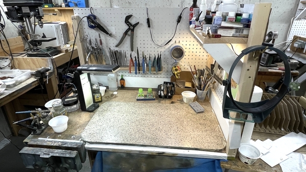
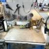
And you can tell that the main part of the project (bench work) is over because the BENCH IS CLEAN! My new organization really helped especially having permanently mounted racks for tweezers, needle files and pliers. I am doing better putting them back in their spots more often. Plus the racks don't take up precious real estate on the work surface. I may but another shelf on the far wall and more puck LEDs. I like the way they light the work surface.
Attachments
Once again, I wrote a post, forgot to hit "post reply" and lost all the images. So we'll do it again. First of all, I hope all of readers in various parts of the country are surviving okay after Ida wreaked it havoc. Just think… sitting here in Louisville, we were missed by the whole deal. The path just went south of the city so we got a smattering of rain. My old home in Bucks County, PA has had more "mid-Western" weather than we have.
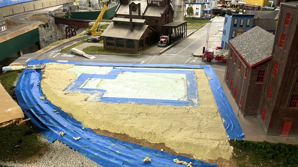
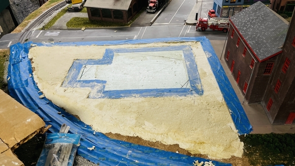
I got started on putting "earth" under the rick house. First I protected the bottom of the model with Press N-seal. I traced the model's perimeter with a fat Sharpie, and then masked the inside of the line so Sculptamold (STM) wouldn't get underneath. I mixed up STM with some earth toned Woodland Scenics color and applied it to the site. I'm unsure about what to do with the "retaining wall" question. I built the STM out further making a more severe slope giving me some more flat surface, but did not install a wall. I don't have any material in the shop to do it. I may just add some rock outcroppings there instead of a formal wall.
Then I got interrupted. Our Internet went out again. It seemed to do this every day around mid-afternoon. It's a pain in the butt. I have to got upstairs to the 2nd floor, reboot the modem, reboot the master Netgear Mesh router, and then reboot the Mesh Satellite in the great room and get the TV running again. The Mesh box next to the TV was acting suspiciously. It was taking much too long to re-sync with the master and kept dropping out. We decided to go to Costco and buy a different brand. The modem is new since I replaced it in July. We bought the Google Nest set, and I installed it when we got back. It was much faster to link up and seems quite solid.
So my plastering came to an abrupt end yesterday. Today we're heading to Cincy to the art museum to see the "Monuments Men" exhibit.
I'll finish up the ground work tomorrow.
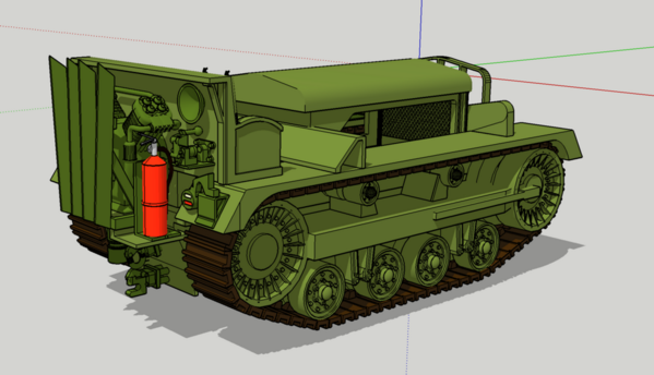
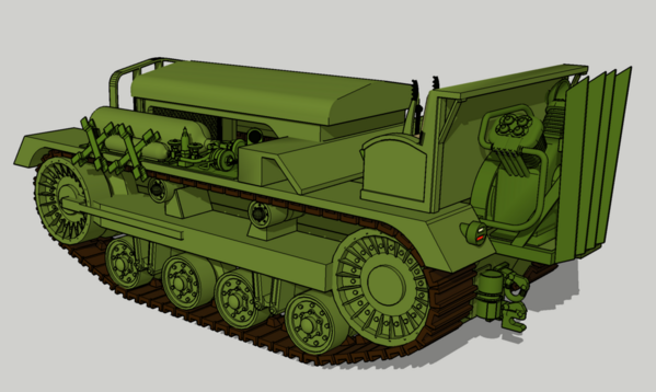
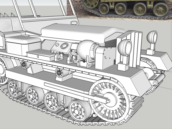
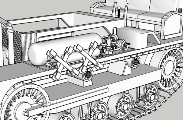
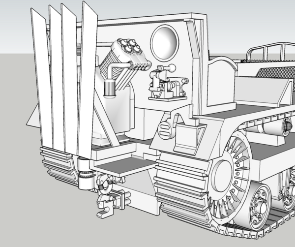
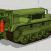
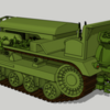
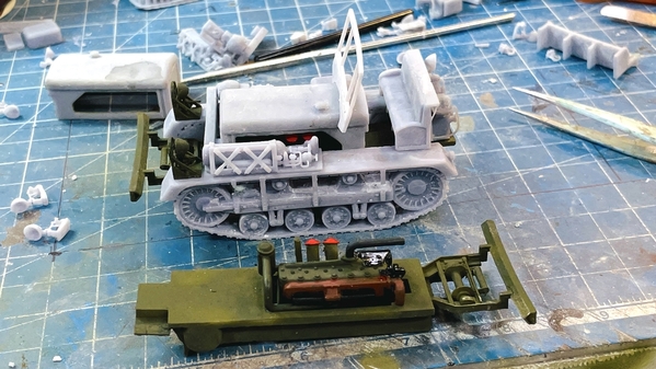
I continued working on the Cletrac model. My detail level is approaching what I'm looking for. Printing is another question. It's a complicate model and printing setup will be the determining factor as to the model's ultimate success.
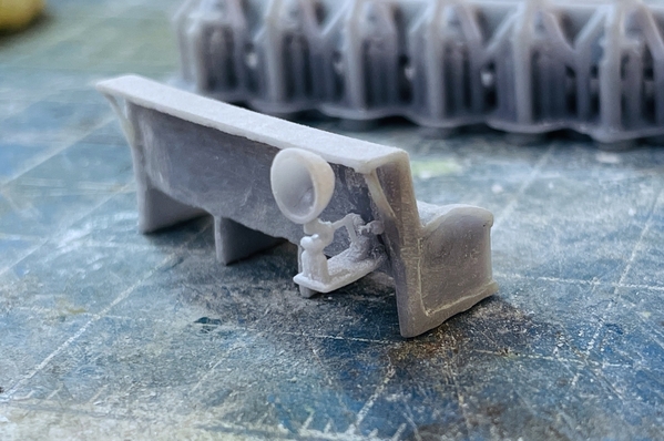
I finished the auxiliary generator that sits on the right fender. The headlights are the ones from the former model. I will redraw them.
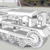
And the complicated air handling system. With all that piping you can see that printing will be a challenge. Not so much printing per ce, but having the details strong enough to sustain themselves after printing.
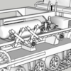
And all the stuff happening at the back end.
I approach drawings like this as one approaches rigging an 18th century model ship. The completed model is complex, but rigging is done one line at a time. When I do these drawings, I draw each detailed subassembly as a unique drawing. I have a setting I use that blocks out the rest of the drawing and only shows the part I'm drawing. It's a bit tedious, but nowhere near as complex as the finished whole is.
Attachments
Myles, we were like you, only having a day and a half of moderate rain and sprinkles. South and east of Pittsburgh were hit with flooding and water in basements.
The site for the rick house looks good. A rock outcropping may be the ticket, making for some more variety in town.
The Cletrac drawings do look complex, but as you say one thing at a time.
With the rocks I have to make sure they don't impinge on any locos going by.
I predicted it would happen… and it did. Buzick Construction has asked for an estimate to build a model rick house for them. Cool… right?
Only one problem. Their first thought was a 24,000 barrel house that is basically a full-size real one. My model I estimate could hold 500 barrels, based 18 barrels per rick bay. That's 48X bigger! If it took me three months to build my model… and yes… I don't do this as a full-time/8hrs/day job, it would take years to build a scale, full-size one, and it would be so massive and unwieldy that I'd have to build it at their location. In other words, they're getting out over their skis. I've asked him to give me some more information. I could build one twice as large, or maybe 3X, but 48 times is not realistic. Nor does it provide any additional value. If you want to show people how they're constructed, a selectively compressed model would serve that purpose quite well. Plus the price would be somewhere around $50k which would scare them away… I think.
You are right about the rocks, you need very low relief.
I thought Buzick Construction would want one as well! Congratulations! Yes, I think they will realize selective compression conveys what they want seen.
The full-size model did scare them away. Then I offered to make them one just like mine which certainly demonstrates all the construction features and would be significantly less money and he's going to present the idea again to the CEO. We'll see what happens.
I've been reading my books on Victorian Architecture and found an important piece of information on the back of the title page. "Plates are reduced 12% in this reprint edition." Boy… glad I found that. It means whatever I scan into the computer needs to be enlarged by 12% and then enlarged to full-sized in SketchUp based on the stated scale on the drawing. It's a complication, not a show stopper.
I just ordered another period architecture book on 2nd Empire structures. All of my buildings with Mansards are considered, "French Designs" or 2nd Empire. The houses that we traditionally call, "Victorian" were actually called, "Queen Anne", "Free Classic" or "English Domestic Styles." We lump all these styles and 2nd Empire into the "Victorian" label. And now you know more trivia.
I'm even thinking about selling Saulena's Tavern to open up that entire city block for more stuff.
Been a while, but some small things have been done.
I got the rest of the base plastering done on the Rick House site and starting crafting the billboard frames. Finished the detailed drawings of the Cletrac M2 High Speed Tractor, and am working on restoring a propeller and building a base for a large metal model (commission job).
The plaster is one and now I'll have to craft the rock outcroppings on the rail facing edge.
I'm building the billboard frame in the same way as I did the rick house: on a plan covered with thin poly sheeting. I cut the poly from one of the disposable drop cloths I bought several years ago when we had the "Great Dishwasher Leaking Disaster" that could have taken out the entire village of Woodbourne, a la Hurricane Ida. Measuring the gaps with the digital caliper and transferring the measure to the stock makes for very accurate fits. I just bought a new one at Harbor Freight. They're $20 bucks and are basically disposable. When the edges get dull I buy a new one. A Starrett precision digital caliper cost many times more, but the metallurgy on a Starrett is incomparable compared to this Chinese stuff. Chinese heat treating or alloys (or both) are terrible. I wonder how they can build jet engines? If I was a professional machinist, I'd have nothing but Starrett.
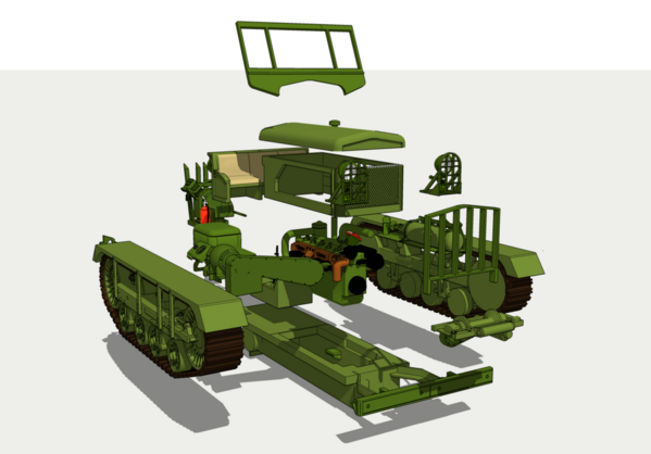
The M2 is complete including a pretty detailed engine. It took me hours to draw all this. I'm now playing around getting the subassemblies ready for printing. I'm not happy with the number of supports that are ending up on very detailed areas. I may have to rethink my scheme and separate them out more so I can keep the details facing up. Currently the model has 18 subassemblies. For such a small machine it's sure complicated.
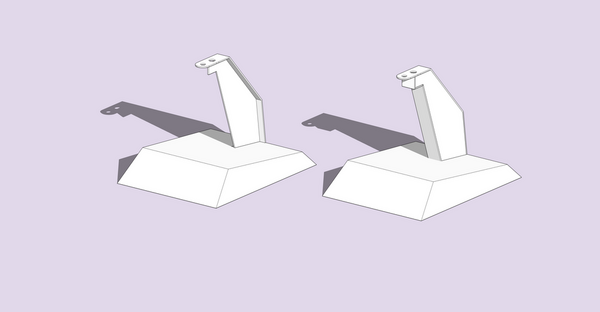
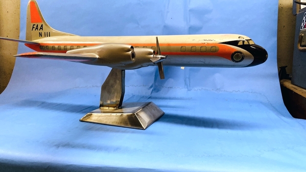
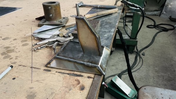
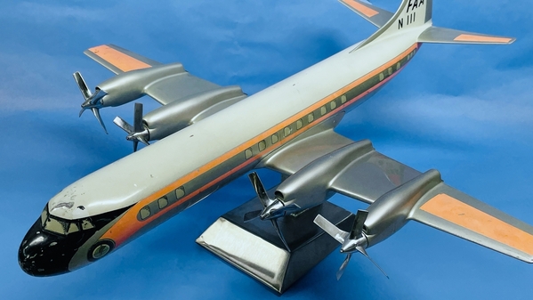
For the airplane project, I drew a stand and am working at a local sheet metal shop owned by a friend. The stand is 18 gauge stainless steel. It's a real bear to work and is tough as nails. I'm still not sure about the structural integrity of the design. On the left is what I've had cut so far, but the right is the mod I'm going to make to ensure it's solid. The model is large and very heavy. I'm afraid that the first iteration is going to be very weak in torque and there's not enough support on the tongue that's going to attach to the model. The first hole in the tongue is for a 1/4-20 screw. The second is for a 5/16" pin.
Fully boxed made out of TIG welded stainless, the re-designed pedestal will be very strong. I did the layout, the foreman did the major cutting on a very large power shear and the folding of the base. I did the cutting and bending of the pedestal. I'll be back in the shop on Tuesday to finish it up.
I'll keep y'all up to date on all my various activities. I also bought a new kind of build plate overlay for the printer. You first glue on a 3M adhesive magnetic sheet and then you simply snap on a flexible build surface. The surface is removable and you bend it to simply pop off all the printed piece, instead of using a razor scraper to get under them for removal. If it works it will streamline that sort-of-sloppy job. It changes the build plate thickness a bit so I downloaded a small 3D printable part that's a Z-axis extender shim to recalibrate the machine for the thicker plate. The Fulament company offered specifically designed extender shims for each of the printers on the market.
Have a great weekend!
Attachments
For what you us it for, getting the disposable caliper makes sense. I have a Mitutoyo (Japanese) dial caliper. I didn't buy it; it was my father-in-law's. It is all I need.
Mitutoyo is ơn par with Brown & Sharpe and Starrett. You don't need to replace them…ever. Chinese $20 calipers wear out every couple of years.
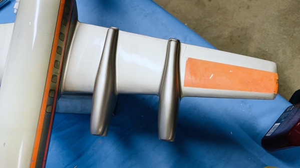
Potpourri day. Working on the billboard, and the turbo-prop propeller for the L-188 restoration project.
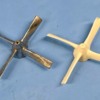
Building a silicone mold without applying mold release before pouring the top half is a terrible boo-boo. While I was literally able to rip the mold apart, it destroyed the clean parting line making a mold that works marginally at best.
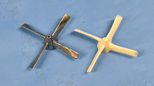
But persistent me tried another pour after opening up the vent hole where the previous air pocket was. It did make a propeller. It needed some added work with Bondic to make it whole, but as a test article it was a good proof of concept. It's not perfect and a bit warped, but it is a propeller and closing matches the master.
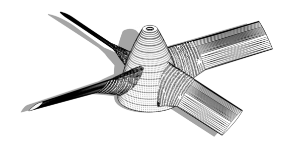
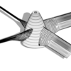
But, I'm also working on plan B. I decided to try and 3D print one. That required drawing this propeller in scale on SketchUp. It was one of most difficult things I ever drew. The blade changes sizes in three directions: twists, gets thicker and tapers wider near the root. SU is not happy with shaped surfaces, but it technically can do it.
Here's the finished drawing showing all the edges and polygons on its surface.
The drawing is made up of a series of formers or ribs, just like an flying RC model. And like a model airplane build, the ribs have to smoothly flow from one to the next so the skin on the surface is also smooth. The tool to do this is the SANDBOX. There are a couple of options and the one I use is "From Contours" Theoretically, the skin should form cleanly going from rib to rib. But that's not exactly the way it came out. Instead, the skin formed in a series of layers going at right angles into the shape rather than across it. I had to go back and remove any errant layer and then hand build the skin drawing a series of triangles from the nodes on each curve of each rib. It took hours. Twisting the parallel portion wasn't hard. You extrude the length from root area to tip, pick just the tip and rotate it. With the root end fixed, the entire blade twists perfectly. The root area was an entirely different animal. Here I had to start with the largest shape at the root, copy it and move the copy forward along a pre-drawn guidelines that had both the twist and bottom taper, and then scale each rib smaller than the last as I moved towards the parallel section. Then I had to clean up the mess from all that errant skinning. I worked a couple of hours yesterday and three more today, but…. SUCCESS. I looked at some videos to see some of the techniques, but in the end I had use pure muscle to clean up the mess.
The end result measures within a couple of thousandths of the overall diameter of the original. I used my digital caliper to measure all the key metrics to build it. It's now on the printer and will be done in an hour or so. I noticed one corner of a blade has a missing chunk, but that's all correctable with Bondic.
If the printed versions work, I may stay with that. If not, I will re-mold the prop and cast more using the low-melting point alloy so it will be real metal. I know what I have to do with the mold to make a better part. It's hard to get some of this stuff right the first time around. I'll post an image later when it comes off the printer. And I will remember to use mold release!
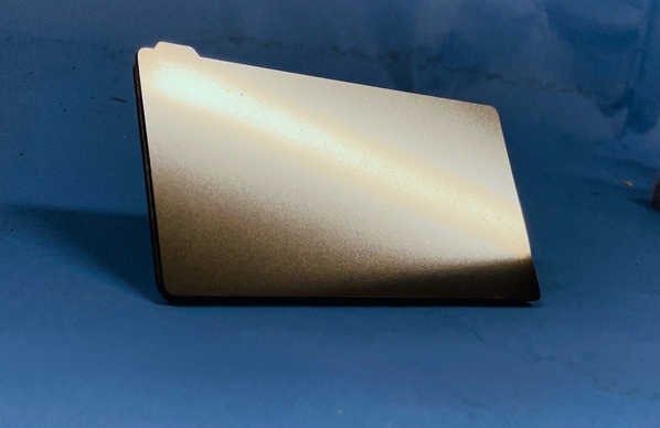
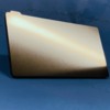
I've purchased and am in the process of installing a removable, flexible, magnetic build plate. It's magnetic stainless steel that is quite thin. When you take the plate off the machine, you remove the thin plate off its magnetic back plate and flex it to pop all the parts off WITHOUT scraping with a razor blade. It saves time, saves parts and saves fingers. The magnetic portion is held to the existing build plate with a very strong 33M pressure-sensitive adhesive. I had a new build plate that wasn't using so I was able to install this new upgrade while still printing. You have to let it set over 24 hours before exposing it to raw resin. I'm interested in seeing how this baby works. This image doesn't tell you much. It's just a nice shiny plate sitting on my photo table. Without scraping, the binding surface will remain in much better shape.
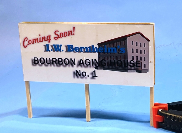
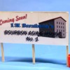
While all this was going on, I finished up the second billboard frame, added the graphics and glued on the posts. Next session, I'll put some cross-bracing on the leg bottoms and it will ready to install on the rick house site. The graphics are very glossy and wouldn't be in real life so I'm going to use some matte coating to kill the shine.
Tomorrow a.m. I'm probably going back to the sheet metal shop to get the L-188 stand welded. When I get home, if there's time, I can finish the billboard and start working on site rocks and ground cover.
Later this week we're heading back east for a wedding celebration, and will be there for next week until the following Saturday. And I still don't have my self-driving Tesla… drat!
On another front, I am not happy to wax political, but this needs to be said. I got a text from my hairdresser last night cancelling my appointment tomorrow due to the fact that she's tested positive for COVID-19. What makes this so noteworthy is that she, and her partner husband, and he son (who all work in the salon) refused to get vaccinated, wore masks only when they were forced to, and generally came up with more bullpoop reasons for this behavior. What makes matters worse, she's 60, immuno-compromised, has RA, takes Humira, and generally has trouble with colds and flu. Her husband is a smoker.
My daughter, wife and I have used this salon for over 12 years, and the person considers me an intelligent person, but I couldn't get through to her that she was simply playing Russian Roulette. She has a 2 year-old granddaughter who she watches a couple days a week and her youngest son is expecting his first child imminently. All of this in now in jeopardy. With her pre-existing conditions, she is a person who could have a terrible if not fatal case. She's had other vaccines in her life, so all the rationalizations were just that… nonsense. She was also putting all of her clients at risk, including a spry women who just turned 101.
To vaccinate or not vaccinate is not a right of choice! Your decision does not only affect you. It affects everyone you come in contact with, love, take care of or are friends or co-workers with. If you choose to smoke knowing full-well the consequences, and you die from all the crap smoking can do, you don't kill other people in the process. If you want to ride a Harley without a helmet, you won't survive a spill, but your head isn't going to kill anyone else. Spreading a highly infectious, killer disease is a different ball game. It's like thinking you have the "Right" to drive down the wrong entry ramp on the Interstate and drive into on-coming traffic. In that case you will kill others besides yourself. Time to get back to real life. If you are not vaccinated, DELTA will get you. It's just a matter of time.
Attachments
Myles,
Wouldn't the full-size rack house be less than four times bigger in each dimension as we are talking volume?
Jan
My rick house is 16" deep X 15" wide. That's 64 X 60 scale feet wide. The 24,000 barrel house is 160' L X 86" W. Or 3,849 sq. ft. versus 12,800 sq. ft. In model terms, the real one would be 40" X 21.5".
Then you have 70 feet tall versus about 18' tall for the model. So to take the math further, you have 896,000 cu. ft. for the real one and 69,282. So the real one would be 13 X more volume than the model's prototype. It's a whole lot bigger than the model that I would want to build.
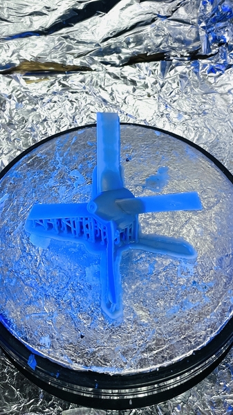
I did get the print done. There's one area that was pulling off a bit and I can fix that by adjusting the supports. Here it is in the UV post-cure chamber. The blue color is due to being bathed in 405nm UV light.
Attachments
The Mitutoyo seemed like a good one, but I'm not familiar. Thank you for the word on it.
The sign looks great!
Mark
Thanks.
Got a terrific stand finished today for the Elektra. I cut and bent most of the pieces and Jim, the welder, at Gettler Sheet Metal, did a masterful job closing all my ridiculously bad joints. Bending 18 gauge stainless isn't my forté and I didn't have bend allowances built into the plan. Bend allowance added dimension needed as the metal stretches to accommodate a bend. The sharper the bend and/or the heavier the gauge, the more stretch. It's not much, but it can add up. To make matters worse, while my design was cool, it was also difficult since there wasn't a right angle in the entire design. Regardless… we did it.
Before closing up the base we welded about 5 pounds of steel plate inside to counterweight the whole deal. By boxing in the upright, all the movement in the yaw direction was eliminated. It is very stable. We cleaned up most of the welds at Gettler's and I have a few more to do in my shop.
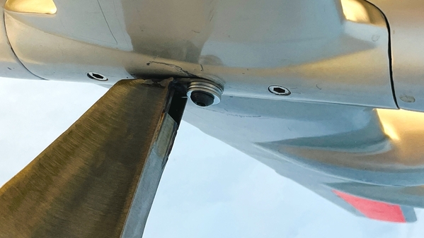
A 1/4-20 cap screw holds the plane solidly to the base.
Additionally, there's a 5/16" stainless rod welded to the stand that slides into the other hole on the plane's belly. it's not going anywhere.
I added four silicone feet to the bottom to make a nice, scratch-free structure.
And a perfect prop just came off the printer. I started using the Fulament flexible, magnetic build plate and it works pretty well. The part didn't pop off as shown in the video, but it did pop all the edges free so my plastic scraper slid right under to remove the part. I like it.
Attachments
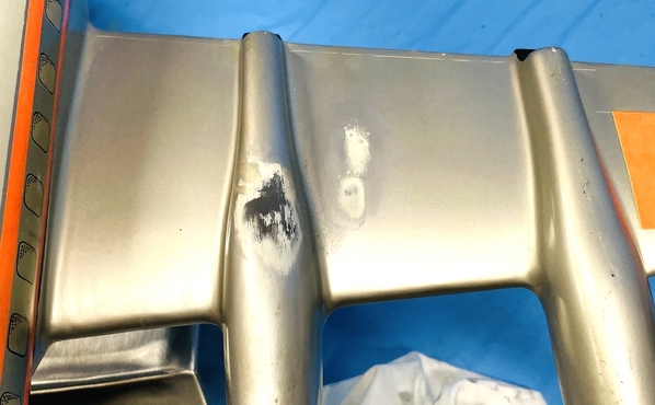
Thought I'd post some more non-railroad status pics. The L-188 restoration is done and I'm delivering it on Wednesday. I ended up 3D printing the missing propeller and finding a way to really replicate metal. I first sprayed Tamiya rattle-can Silver, then rubbed on a coating of A-K interactive "real metal" wax-based metallic silver (like Rub-n-Buff), but it wasn't reflective enough. At my LHS they suggested buying one of the broader tip Molotow Chrome Pens and decanting its contents to air brush it. That worked perfectly. What happened next was almost a catastrophe. There was some cream-colored blemishes on the left wing mid-section and inner nacelle. I attempted to polish it off, but it didn't budge. I then tried IPA, no response. Then I used the nuclear option… I wiped it with MEK. I then found out the truth. The blemish was on not ON TOP of the paint. IT WAS PRIMER SHOWING THROUGH. The blemish now became bigger… much bigger. I needed to refinish at least that part of the wing.
The plane's metallic paint had a definite yellow cast. Don't know if it's the actual paint color or the yellowing of the top clear coat. I used a mix of Alclad gloss aluminum and Alclad light burnt iron. I could have even made it more yellow. Looking straight at the paint its color is very close, but when viewed obliquely, the paint I used looks darker. Again, it's a huge improvement over the mess that I made. I used Alclad aqua-based clear gloss, and then after letting it cure for 24 hours, rubbed it out with my abrasive polishing set (from 3200 grit to 12,000 wet-sanding pads) and then with polishing compound. The gloss is the same. From this angle the color is really close.
If you can't tell, the 3D prop is on the far right. The chrome props have a different cast (more blue) than the made prop, but it's close enough and the client is pleased. From this angle, my wing panel is a bit darker. You can see how reflective the panel is.
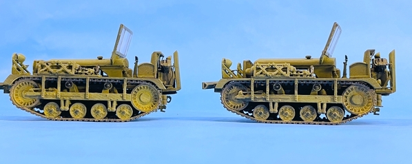
Now onto the M2 Service Tractor. I'm almost done this major project. I've got two more parts to print. I've reprinted several items to get better results. For example: I found that making the frame 3 pieces (frame, winch and bumper) created a warped and weak structure. I was able to successfully print it in one piece.
I also implemented a new process. I ordered and installed the Fulament flexible build plate on the my Elegoo Mars. This was a FaceBook ad, believe it or not. It's a two-part affair with a 3M adhesive magnetic layer that adhered to your existing build plate and a thin, stainless steel build surface that made of spring steel. The build surface is held magnetically to the 3M magnet sheet. If you've had a successful print, you no longer need to unclamp the entire build plate to remove the printed parts. You simply remove the magnetic surface.
The surface is spring steel so you can massively bend it to break the part's bond on the surface. Big parts just pop off…. no more scraping. But in my case, since I'm printing so many small parts, bending the build surface doesn't pop them off. If I work it a bit the edges my release making it much easier to scrape the parts off. Either way, not having to remove the entire build plate assembly says a lot of time and clear up. And best of all. The plate has great part adhesion and my failure rate has dropped to almost zero.
Something else has improved production rate. I now put on supports in the following steps.
1. Use auto-supports set to "Heavy" and do "Platform" only. This applies supports all over the part as long as they can be reached directly from the base.
2. Remove all heavy supports above those that are holding just the bottom edges of the main part.
3. I redesigned my "Medium" supports to give them fat base posts (almost the same as heavy), but with much thinner attachment points. I found with the medium and light support original settings, the supports themselves were failing causing the upper parts of the job to fail.
4. Use the upside down view in the ChiTuBox slicer and apply by hand, medium and light supports to areas that are showing red and bright red color indicating unstable areas or areas that will create islands. ChiTuBox is very good at showing where island-prone areas are.
Between the new build plate and the changes I've made in support stratagem, my failures are almost gone. There's still the occasional failure due to a lousy design, for which I take full responsibility.
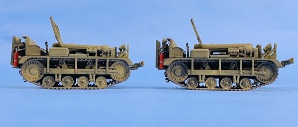
I'm only building the 1:48 version. The fellow who wanted the 1:72 bowed out when I raised the price due to even more drawing time would be consumed to modify the 1:48 detail level to work at 1:72. For example: that air handling modules would not print that way in 1:72. I'm going to paint the models before delivering them as a result of the engine being in a place that would defy painting after assembly. The tractor is not glued in this image. Just posing.
I made a lot of those lights to get ones that I didn't break.
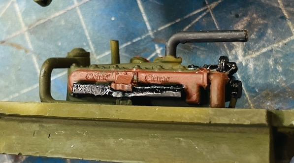
I was even able to print the "Cletrac" logo on the exhaust manifold a la prototype. You won't see much of the engine since it's quite buried in the cowling.
Model should be done sometime next week. Meanwhile, I'll get back to finishing the rick house.
Attachments
Been a while.
First of all, Mark Boyce is now the proud owner of the Idaho Hotel. We met at a Sheetz station on route 22 in Monroeville, PA and made the transfer. We were on our way back to L'ville from State College, PA.
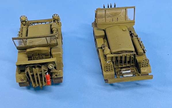
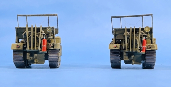
Second, the M2 Cletrac project ended with delivery to the owner of Scale Reproductions, Inc., and he's going to put it on display to see if additional sales are in the offing.
Lastly, I've started working on the SB-60B Seahawk Helicopter and will finish up the Rick house site in the coming weeks. I now have a 16 X 8.5" bare spot in town that's wont for a new structure. I haven't yet decided what that's going to be. I will take suggestions from my readers.
The M2 project was very gratifying since the entire thing was created just from photos resulting from a Google search and one crude line drawing that gave the overall size of the unit.
The windshield on the right side unit is NOT cockeyed. That was an optical result of the angle to the camera.
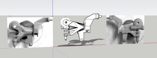
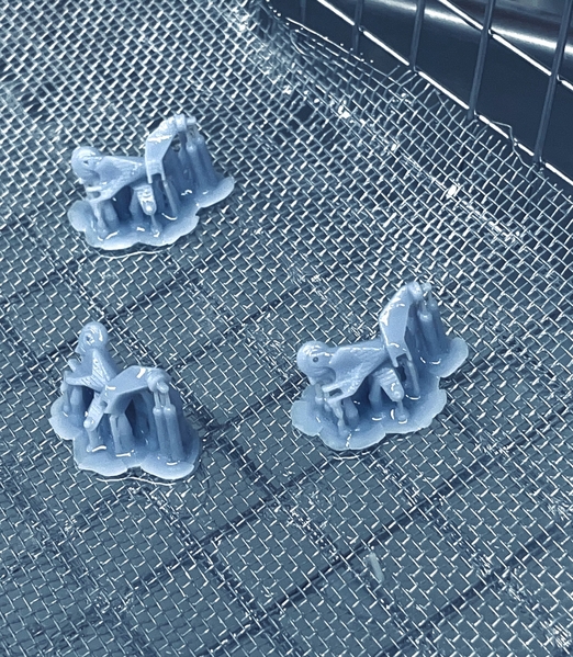
The helicopter has a critical rotor part that was molded backwards! The part and its pair should have both been the same hand. Instead they produced a right and left hand version. The left hand is wrong. I found instructions on the web to cobble together a correctly-facing version cutting and gluing. Instead I redrew the part and 3D printing it. I only need one, but I'm printing a bunch to make them available to others building this kit. My first run only had 30% successful parts. The rest stuck to the teflon. Don't know why that happened. The printer's been pretty good lately.
The part has a pretty thin part and I'm redoing it to fatten it up a bit. I measured the part to the nearest thousandths, and then drew it 100 times larger in SketchUp. SketchUp likes to work in larger dimensions. I then reduced it by .01 to make it back the tiny model size.
Attachments
Myles, The M2 certainly is a strange beast, but your models look great!
For everyone else reading, it was great meeting Myles and his wife Michelle to pickup the Idaho Hotel. We talked for about 20 minutes and then headed on our ways. Myles and Michelle are both very friendly and easy to talk with. I am glad to have met them in person.
I haven't decided where to put the Idaho Hotel on my layout, but this space was open. Myles commented that he thought it was great that I can get a full view of the most interesting side, the front. It is just the ticket for a West Virginia mountain inn on my layout.
Attachments
![]()
Myles,
You never cease to amaze me. Great work.
The feeling is mutual!
Now for something completely diffierent...
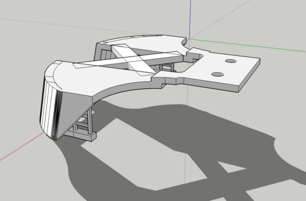
I had a couple more commission projects involving the 3D printer. One is recreating the pilots on a K-Line NH "Jet" electric loco. The Zamac cast pilots had gone to the dark side and were completely crystalized and were crumbling. I attempted to drill and wire the front cross-member so I could repair them, but as the drill entered the metal it just crumbled more. It had to be a complete remake starting with drawing the pilot. It was hard to determine the sizes since I was looking at pieces. I snug them together as best as I could to get some overall measurements and took pictures. I scaled it all in SketchUp and then enlarged the drawing 100x so SU was happier. SketchUp is funny when you're working at small sizes.
You can see the fracture lines permeating this entire part. Our models will not last for ever even if don't ever play with them.
There's actually a critical part missing. There is a flat plate that was attached to the tangs on the right side that had the two countersunk screw holes which holds this thing to the trucks.
Here was the drawing. I radiused some of the corners to prevent fractures there. The holes need countersinking as a post-process.
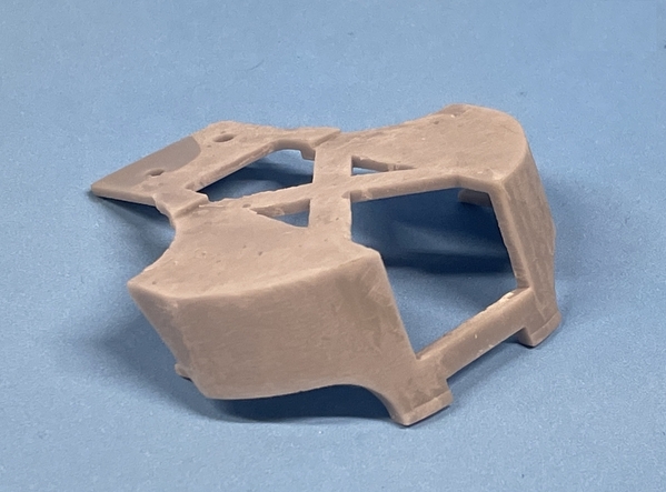
I drew it with the integral ladders. On the original the ladders are added plastic pieces (as are the air lines). Here was the test print. The "X" brace is there to stabilize the part and keep it from warping. It does get in the way of the remote coupler leads, but that's not a show-stopper. Wire I could have printed this with the air hoses attached, they would be fragile and probably break off prematurely.
Yesterday I took it to the hobby shop and we tried it on. It fit perfectly! I'm now going to print one for the other end. One of the ladders broke away and I changed the design to add an upper brace. The broken ladder was fixed with CA at the hobby shop.
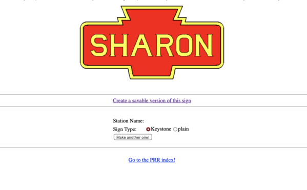
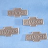
Another quickie project for another fellow who works at the hobby shop. There's a website as part of the PRR Historical Society where you can design your own PRR station signs. He requested one for the "Sharon" station. I drew the size in the app, then imported the drawing into SU. I re-drew the sign with 3D raised Copperplate text.
http://prr.railfan.net/cgi/mak...=SHARON&type=key
Here's the sign as it appeared on the website.
And here's the SU drawing.
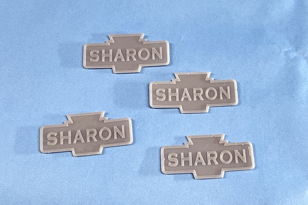
And the finished print. Thin objects like this only take a few (15) minutes to print. The do warp a bit so it needs to be glue to a rigid substrate. Took about 8 cents worth of resin to do this.
The First Build manufactory at University of Louisville is now open again to the public so I'm starting to noodle the next projects that will need laser cutting. They have a couple of 48" monsters there that do just about anything.
Attachments
I'm glad to know the First Build manufactory is open again for your use!!
Is that sign for the station in Sharon, Pa?
Now I have to decide what I want to make there. I need to fill up that space that you caused on my layout.
I'm glad I was able to give you a challenge! ![]()
I think I have the next project.
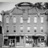
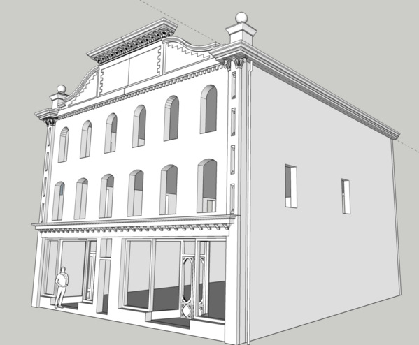
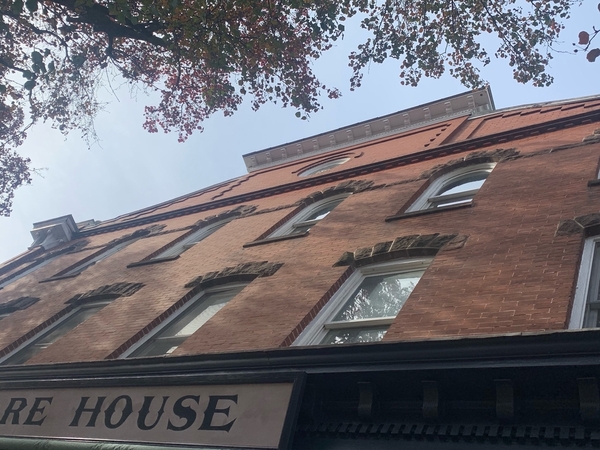
In my previous Bucks County, PA town, Newtown, there is a landmark hardware store. Newtown Hardware and it's building has been a working hardware store since its construction in 1869. The building burned in 1899 and was rebuilt to its original design. The only change I can see is the pediment at the front roof peak. It's got some really nice decorative brickwork and cornices on the front that will make some interesting laser cutting like the distillery, and there's sufficient details for some 3D printing as well. I was able to get some good images from Google Earth and the building was given a 3D skin. On Newtown Hardware's website there's some history and where I got this great straight-on frontal shot with the original roof details. Combining the two, I am able to create a reasonable replica in SketchUp. Being a traditional store front, I can use Tichy store front plastic if I don't want to fuss with that.
Originally the building was two stores: the hardware on the left and a dry goods store on the right. The hardware owners bought the other store and opened the wall. That double store exists to this day. They still have the wooden drawers with the screws and nails. The floors squeak when you walk and it has a neat old hardware store smell. It is a treasure.
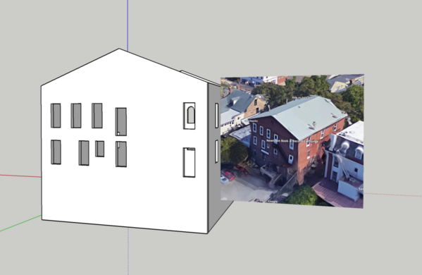
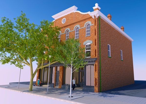
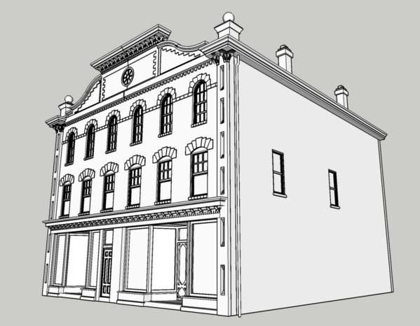
According to Google earth, the building looks like it's 45 feet wide and about 54 feet deep. I may have to selectively compress the depth, but I have the width where Idaho was. Here's some screen shots as I draw it on SketchUp.
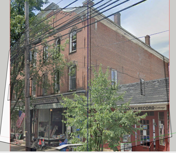
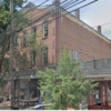
This is a street view shot from Google in SU's Match Photo where I'm drawing the 3D version directly over this image. There is some differences in building shape due to distortion from the Google mobile camera.
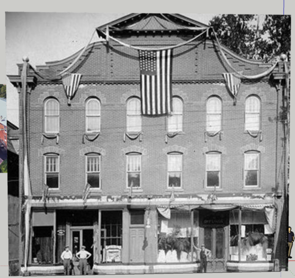
Here's the frontal shot superimposed over the drawing. Comparing this to the above you can see the pediment change at the roof peak. This image also gives good detail of the fancy brickwork. After the distillery, I know that I can create that. The center door leads to upstairs apartments. I don't know what holiday was being celebrated… probably July 4th. There's bunting blocking the view of the below-window area.
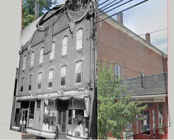
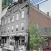
And here's the above superimposed over the match photo contemporary image.
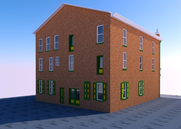
And because Google Earth lets you see the backs of existing building especially when they've been 3D skinned, Here's the back with the image next to it to show the window placement. There're more windows to go into the back. The actual lot actually drops off front to back due to the downhill slope to Newtown Creek that runs behind the building's parking lot. Therefore; there's a basement access in the back at the lowest level. My lot is level so I'm going to have a metal door lift up basement entrance in the back. There's a back door to the store up to that pressure-treated lumber deck you see in the rear image. I will make that door ground level. Being a hardware store gives a lot of opportunity for stuff in the back lot to add interest.
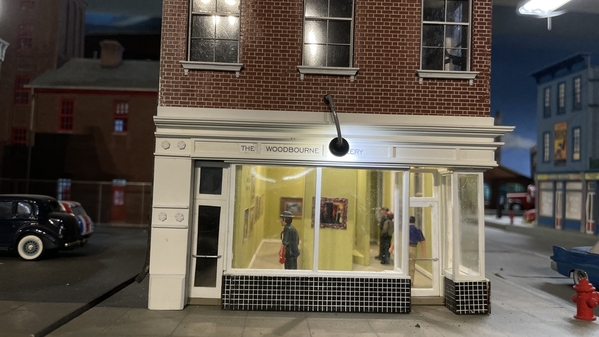
The building is three stories plus. It will work since the Woodbourne Gallery is already that big. Only drawback is the front will be facing away from the viewer from the front aisle. That's why I have to make the back as interesting as possible. As Rachel Maddow says, "Watch this space."
Attachments
Myles, that is an excellent choice! The photographs and interior description reminds me so much of Pfeifer's Hardware (originally Zeigler's Hardware and 5 and 10 in Mars, Pa three miles from where I grew up.
Myles,
Where did you obtain the copperplate font?
It comes standard with SketchUp Make 2017 in the 3D Lettering function.
Thought you'd all like a progress report on the Newtown Hardware House project. I contacted the manager of the store and he took some more detailed pictures of the building. He was very interested in it. Our Philly friends also know the owner of the store and she wants to share the project with her. They may want a model of their own. The brickwork on the facade and particularly the pediment is pretty complex, but after my distillery project experience, I know exactly how I'm going to lay it out for laser cutting. I will 3D print all the cornice details including 3 different corbel styles. The sides and rear aren't very remarkable, but the first floor windows have shutters. I can buy the self-stick laser board from Stephen Miley at Rail Scale models. The walls will be 1/4" MDF. I think the stone lintels over the windows will be laser board and I may try and engrave some texture in them. I could also 3D print them with the texture. We'll see… Each project that preceded this one gave me the experience needed to master all this nuance.
This is a view of the real pediment. Notice the different levels of relief on the various brick details. I still have to put in that round window. Don't know what the mullions on that one are since a tree blocks a direct shot from across the street. We're going to be back the area over the New Years holiday and the tree will be free of leaves so I'll be able to get a better shot of it. You can also get a good view of the lintels in this image. There's three kinds of dentil molding in that front as well. Like I said, it was more complex than you originally think.
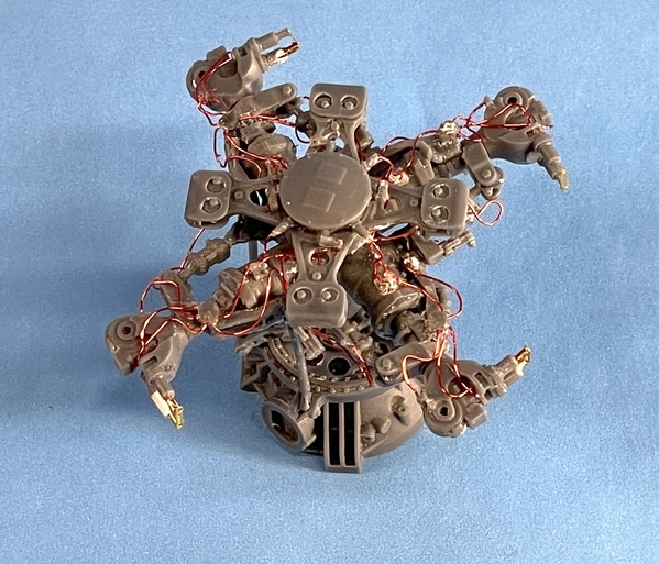
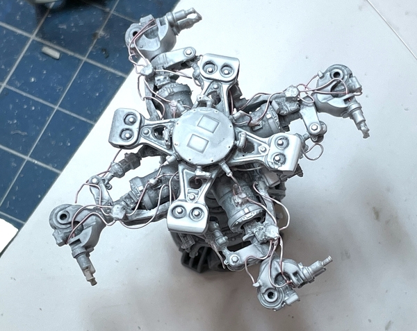
The Seahawk project is coming along. I've purchased aftermarket resin kits for the right T700 engine, main rotor, tail rotor and the hinge assembly for the folding tail boom.
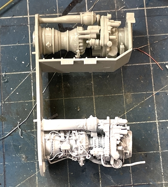
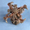
The engine took a week to build with all the added piping. It was worth it. The top one is the kit engine that will not be exposed. The bottom is a ResKit model of the GE T700 turboshaft engine. Painting this will be fun.
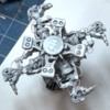
I'm also building the main rotor kit and it's just as complex and challenging as the engine. It too will add a tremendous amount of interest in the build. What you see hear is already 16 pieces all glued together with Gel CA. There's a large amount of hydraulic lines that get added to this. The naval version is more complicated than the Black Hawk version due to the requirement to fold the blade while onboard ship. Those twin pins you see are hydraulically actuated to insert steel pins into fingers on the blades to lock them in the operating position. When the blades are locked, the pins are in and can be detected easily by those brass straps being in the "in" position.
Attachments
The hardware building does have some neat intricate brickwork! Those old buildings are really cool
I'm almost finished the Hardware House drawings. All that's left is changing the trim under the front store windows. It was a bear to draw, but it's pretty close to the real thing. I'm also making progress on the SH-60B Seahawk. Piping the main rotor was also a bear and tested my mettle to the max. Still have two tiny pipes to add that I missed. No one would know.
Three different corbel and dentil molding designs in one building front….
For reference, here's the back. I'm not sure how to handle that scary fire escape. Notice the 6 X 6s holding the whole deal up. Tichy makes a fire escape set in styrene which I think I already bought. It could be printed, but it wouldn't be easy. Might be easier to solder it together out of brass.
The real site sloped back exposing more of the basement in the back. Mine is flat so I'll be using a different basement entrance.
Here's the rotor head. All the wires are magnet wire (less than .3mm) and are in 0.012" holes.
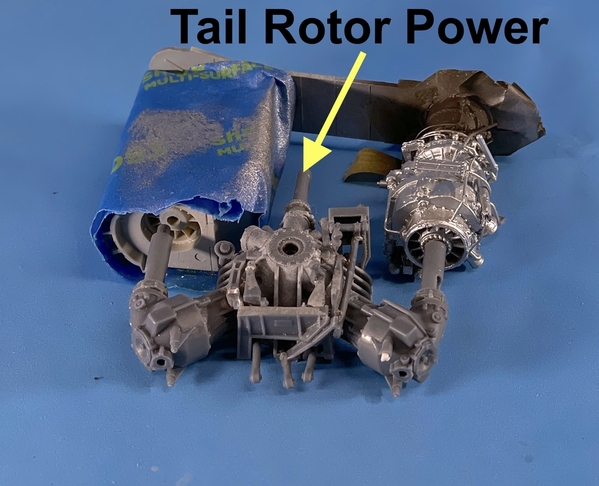
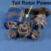
The transmission is just as complex without all the hydraulics.
The real one… All the complexity under the mech's feet in the hydraulics bay IS NOT reproduced in the model nor will I attempt to do it. Those floppy weights on the ends of the four arms in the picture and my model is the Biflar vibration damping system. Those weights are tungsten and they move freely about an axis acting as a pendulum that cancels at the source rotor induced vibration. It reduces in-cabin vibration by 55%. The fact that this is a Navy bird drastically increases the complexity of the rotor head to enable the rotor blades to be folded (as they are in the image). Both the swinging of the rotor to the stowage position AND the locking of the blades in the fly position are hydraulic and remote controlled. One more pipe to add when the blades are installed is the nitrogen crack sensing system connection. Blades are hollow and nitrogen filled. It there is a crack, nitrogen leaks out and is sensed. It sends and alarm to the cockpit to immediately get the blade changed.
Attachments
That is a scary fire escape. It may be better to jump! 😉 The drawings look great!
Those rotor assemblies are quite remarkable! What a lot of tedious modeling. What scale is it in?
Thanks Mark and others…
The store would like a model if I wanted to build them one. What I don't know is are they willing to pay something for it. I suggested that I'd eat the labor if they would pay for the materials. That's the deal I gave the Heaven Hill Bourbon Experience Center which has a distillery model.
Now I have to import all the flat parts into CorelDraw and scale so I can produce the laser cutting drawings. I can buy the Self-Adhesive RC Board from Stephen Miley at Rail Scale Models which I'll use for the fine detail flat parts, i.e., windows, doors and some trim. All the rest of the flat parts will be cut at U of L's Maker's Lab out of stock they have on hand. All the 3D parts are already designed since I had to draw them all in the master drawing. That said, the long cornices have to be broken apart into smaller chunks to fit on my modest little printer. And I'll have to draw all those bricks! I am better at that than I used to be.
We are looking forward to seeing this project come together!!
All of the drawing and design tasks are done including all the 3D printing development. I'm waiting on some specific answers from the First Build people on the actual, exact thicknesses of their available stock and the detailed program specs on their laser cutter software. My previous suppliers used line thickness in the Coreldraw drawings to determine if it was cut or engraved. The First Build machine uses that plus line color. I need to know what these specifics are before I can bring my drawings downtown and produce parts.
The stock thickness is necessary for the fit of the floors, roof, trusses, etc. It's nominally 1/4", but it's more like .218" or .228".
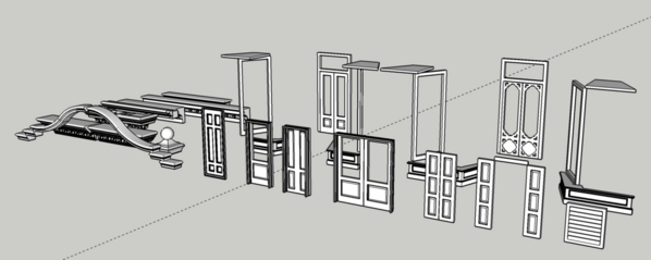
Here's the drawing showing all the pieces that are going to be 3D printed in my shop. The store show windows, while shown here, I'll probably scratch-build them out of styrene stock.
The cut drawings consist of four sets based on the material thickness:
- thick stock for walls and floors (nominal 1/4")
- 1/8" for roof panels
- 1/16" ply for brick overlays (pilasters, upper pediment work)
- RC Board (a laser cut product) that self-adhesive for all windows and stone lintel and details.
Here's the thick stuff not including the floors which are boring. I need to stop, but I edit it later. Hi… I'm back… if you don't post it times out and you have to start over. It's easier to just post it and go back and edit.
Here's the thick stuff:
Placing the bricks is simply complex (or complex, but simple). I start with a couple of rows of bricks consisting of a few long mortar lines and short brick lines. I then copy and paste this once, then select both and copy and paste again. Then I select all of this and do it again. Then I select and paste downwards. So in a matter of a few minutes I go from twenty or thirty lines to 35,000 lines. In this project the real brickwork had a bonding layer every 10 courses. I used my Bronx Victorian brick work as a starting point so even that didn't need to be reinvented.
That's the simple part! The complex part is when I "Power Clip Inside" the building outline all the bricks. This is down with a copy and then a click inside the object and POOF! the bricks are nicely inside the image. If I was just doing a drawing for drawing's sake, I would be done. But I'm not! The laser cutter cuts on .3 pt lines and engraves on .7 Pt. lines. So any place that a brick line interferes with a cut line, the cutting would cease and it would be engraved instead. So I have to go through the entire drawing and find any of these overlaps and edit the bricks to clear the cut line from any interference. This is done with the "EDIT POWER CLIP CONTENTS" choice. It's not difficult, but it is painstaking and time consuming.
There are two more pages, but they're just inside floors and are boring.
Here's the ply parts. These represent all the interesting brick overlays. The pilasters are four layers to set up that brick stair-step pattern from bottom to top of the openings. I have a set of doors and shutters for cutting as a back up. I'm also 3D printing all of them to make the relief panels in 3D. They're my provisional parts. I'm also printing doubles of the long brick dentil molding and pediment overlays just in case. I'm not paying by the cut. At First Build, it's a flat fee for the machine and you pay for materials. More parts in this case does NOT equate to more material, just more cutting time.
The next batch are the RC Board self-adhesive parts. I always cut extras of these since they can break during fret removal and assembly. I use clear styrene for glazing.
The little gaps you see are put in after the parts are drawn. They are tabs that hold the cut parts in place during cutting and handling. I've learned to put the notches in very quickly since I've now draw SOOOOO many windows.
Once I find out those specs, I'll put the final touches on parts affected by the thickness and start producing parts. Meanwhile, work continues apace on the helicopter.
Stay tuned...
Attachments
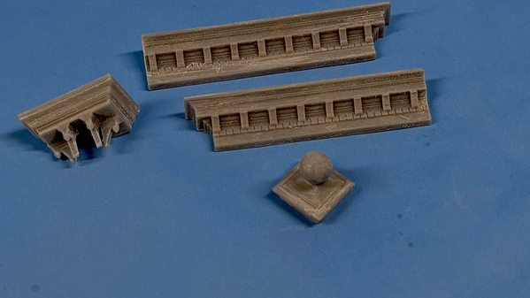
Two things happened today! First I got the first successful prints off the machine. The lower cornice that goes over the store fronts is three-parts due to the small capacity of my Elegoo Mars printer. I printed the two ends and they came out great. The other print was 50/50. One corner cornice with corbels came out perfectly. It's mate failed to actualize. The other was one of the caps of the corner towers. It too was perfect and its mate failed mid-print. I've surmised that either the surface grip on the left side of the Fulament build plate was less than the right and/or the bed may not have been level. I leveled it and gave the build surface a light sanding to break any glaze that formed.
The coolest thing was I drew the cornice's corbels to be open on their inside and the printer reproduced that exactly.
The second good thing that happened was getting the data I needed on the laser cutting. I took my grandson to the airport (he's going skiing with his other grandfather in California) and then stopped 1st Build to see if they were open, and, if so, that I could get some stock measurements and the laser cutting parameters. They were open. Not only did I get the data I wanted there, but I was able to go on the Web and find the operator's manual for their laser. I'm going to learn it before I go and cut anything.
It's really reasonable. The ply I'm going to use is $1.30/Ft sq. My material costs will be well under $100. And it costs $2.00 per job which equates to about two bucks for each sheet I cut. I have 10 sheets total so my cutting costs will be $20. Any way you cut it, it's a good deal. I'll probably have to make a couple of trips since their only open to the public for a couple of hours per day.
This is the laser. They have two and their big.
This is the cutting sample you can use to determine the speed and power. I think 100% power and between 50% and 70% speed.
For cutting the 1/8" (.200") ply 100% power and 2.% speed and 300 PPI (pulses per inch).
Stay tuned. Things are going to get good.
Attachments
I'm glad to see this project moving forward! I do see the openings in the cornice's corbels. They look great!
Thanks Mark! But wait… there's more!
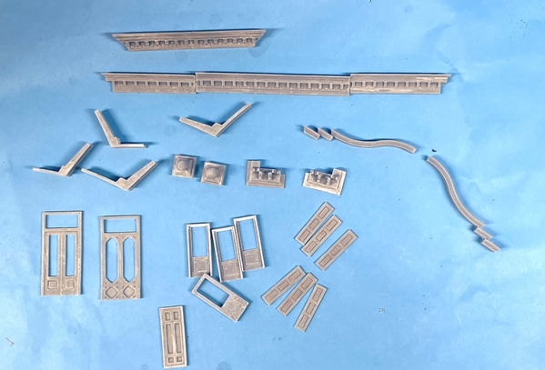
More 3D printing success. I was having failures only on the left side of the build plate. That could be a leveling problem, so I re-leveled the build plate and re-sanded its surface to give it more tooth. This did the trick. All the prints since then have been perfect with no separation from the plate. I printed the long center section of the store front cornice, the serpentine molding that tops the pediment brick work, and the complex 2-part top cornice that sits on the pediment. The last thing that came off the machine is the left storefront door, the mid-door and one of the four pieces of the store window bases. I didn't take a pic of that last one… it's still hanging on the machine.
This one printed beautifully right on the plate with no supports. It had a solid back and no overhangs that needed any supports. These are attached to the Fulament removable, flexible build plate. It sticks to the machine with a broad 3M adhesive magnet sheet that firmly attached to the existing aluminum plate on the machine. You just pop it off, bend it, and the parts detach. Small parts don't break loose so I use a razor scraper to remove them.
This part gets joined in the middle to make one large part. Can you imagine making this part "old school"? I wouldn't no where to start. By being able to draw it in SketchUp, the curves are all true ogee, the corbels actually have roundels on the flanks that reproduced correctly. With this complexity, I probably wouldn't even consider building it at all.
The architectural parts printing is going faster than I expected. I'm doing two to three loads a day with the printer running all night. Unlike a string printer, when this little guy is lined out, you can leave it alone and it just does its thing. It's always exciting coming down in the morning and seeing some nice new parts hanging there waiting for you.
I will probably do the laser cutting early next year after the holidays. I woke up thinking about the changes I need to make on the laser drawings now that I know the true thicknesses. I might go the same way I did with the Woodbourne Gallery; beveling the corners so the brick lines would line up correctly in the corners. This makes building harder, but it looks pretty good. I kept the 45° sanding fixture so there's that. I'm wondering if I can use it in conjunction with my 4" belt sander. I could rough the bevel on the belt sander and do the finish work with the bevel fixture and a piece of sand paper attached to my granite surface plate as I did the last time.
Attachments
And we're off...
Can't wait to see more progress Myles!
Dave
I agree, I can't imagine making the curved parts using conventional modeling methods. All the parts are looking great!
Thanks guys! I just noticed… this thread has reached the 100 page milestone.
The printer is running full out and producing parts without defect. The fixes I did (leveling and sanding the build plate) solved the adhesion issue. It printed all last night, then another load this morning and lastly one finished this evening. At this rate, all the parts prints will be done next week. That said, if I do any interior stuff and don't just use photos, then printing will continue. I'm designing the build so the interior will be reachable even when finished.
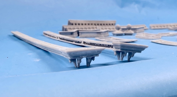
Here's more parts. They're sanded and post-cured. After the pic added some filler to the top cornice joint. It will be almost invisible. The single upper-story back doors are hanging on the machine now and are perfect. I still have the long eaves cornice (6 parts) and reprinting the corner cornice and ball tower that failed earlier, and the lower back doors and the shutters. Lastly I have the right main door and three more store front bases.
I bought a piece of 1/16 ply at the hobby shop for those laser print parts.
I decided to use the mitered corner method and changed the CorelDraw laser drawings to reflect this and I also adjust any lengths affected by the thinner wall thickness. I'm not changing the floor sizes since I want some play in them. I'm going to make it so the floors load from the bottom. I drew some roof trusses that will also be cut out of the thick stock. I had room on the sheet so it won't add any cost, just a little more cutting time.\
For any of you who have access to SketchUp, I've just uploaded this model into their 3D Warehouse. It's the complete file and is in full-scale size. All my SU drawings are done in 1:1 scale and then scaled when I either load parts into CorelDraw or shrunk to make 3D parts STL files. Most of my other notable projects are on the warehouse also.
Attachments
More printing and a few more problems. Sometimes things fail with no apparent reason. I'm almost done the printing part of the job (exterior only). I was going to take more pictures of the interior when me made our New Years trip back East, but we cancelled due to the increased COVID risk. It wasn't just the risk. It was the insecurity of the trip itself. What would be open? Hotels, etc. I may ask the proprietor to take the pictures for me.
I have 10 shutters printed and need 10. There's one window that has the shutters closed making 12, but the closed back is just flat so I can use styrene for that one. So that's done. All that's left is the long cornice running front to back on both sides. I'm printing that in 6 pieces. I changed the FEP recently, but it's been sticky in some places. Here's an example.
This was yesterday's second shutter run. I re-designed the support scheme since the supports failed on two on the previous run. In this case here's what happened. This is the job hanging upside down right on the machine. It's on my removable, flexible build plate. Four printed perfectly. One has only a base without supports, and the other has nothing… nada… bupkis! What's missing is a blob stuck to the teflon at the bottom of the vat. It means removing the vat, emptying the content through a fine-filter funnel into a bottle, cleaning the resin and somehow removing the remnants without destroying the FEP in the process and putting it all back together. All in all it kills 15 minutes. And I don't like doing it.
So here's current production without the four shutters not yet off the machine and the long cornice parts.
Attachments
Attachments
That works, but the beveled panels make for some difficulty with the horizontal edge forming unsupported on its extremities. I try and do vertical whenever possible. I pay a lot of attention to the bright red areas on the slicer.
To remove the failed print from the FEP add a little resin to the vat. Then place a piece of support structures in the vat. Expose the the resin. The holding the supports, remove the hardened resin. I saw this tip in an "Uncle Jessy" video on youtube.
https://www.youtube.com/c/UncleJessy/videos
Jan
That could work! Apparently, there is a "Clean Vat" selection on the Elegoo Mars. I will try it the next time it happens. This time, I popped off the pieces using a very carefully applied razor scraper. But the FEP was already damaged so I replaced it. I also did some more research on adhesion issues and, based on what I found, reduced the number of layers on the raft level while increasing the exposure time of same. I also changed the geometry settings for the raft. The changes worked perfectly and I printed 6 pieces of long wall cornice in two 3-piece batches.
I cleaned these parts along with the remaining shutters. I then glued all the long cornice pieces together so they're done except for a final wash and painting. To that end, all the 3D printed exterior details are completed. I'm holding off going down to U of L to do the laser cutting until this Omicron spike burns itself out. It was a good decision staying put during the holidays. It was low-stress for us and we're still well as of this moment.
Here's the long wall cornices all glued up. They're bit warped, but my resin mix has some give in it and I will make sure it's straight when glued on the wall.
I also glued the over-the-store cornice together so all of them are in their final form. Here's all the parts waiting for further processing. The way these parts are sitting there kind of shows the over foot print of the future building with the over-the-store cornice being almost the full width and the long cornice giving the depth.
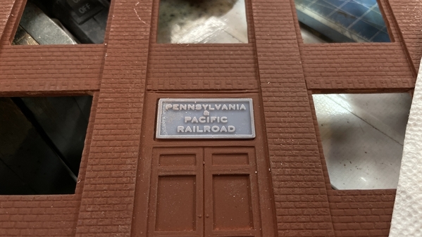
I will do a final clean and spray the parts with primer. I can also paint the colored parts at this time. Meanwhile, work continues on the Seahawk and I have another building to construct, the Korber Power and Light Office building that I got in trade for some 3D printing I did. It's a 6-story office building that I'm going to build for the open space between the tracks in back. I'll rename it "Pennsylvania & Pacific RR" headquarters building.
Attachments
Been a while since I posted due to:
A) working feverishly to complete the Kitty Hawk 1:35 Seahawk SH-60B model. I posted this blow-by-blow on four plastic model forums and was able to detail it beyond my imagination because one of the readers is a Seahawk Naval pilot.
B) U of L's Makery was closed to the public due to COVID. It finally opened again this week and I am ready to laser cut all the parts for the Hardware store project. And when I do, all y'all will be privy to the agony and ecstasy of the build.
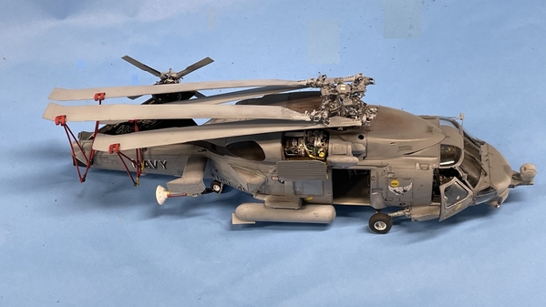
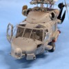
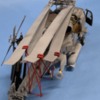
Here's the Seahawk: This, believe it or not, was the most challenging model aircraft I've ever tackled. This was based on several factors. The Kitty Hawk instructions were ambiguous sometimes and missing things other times. The styrene was somewhat brittle and broke at the worst possible times requiring drilling tiny holes and pinning things with Phosphor-bronze wires. The ResKit add-ons (Main Rotor, Tail Rotor, starboard side GE T700 turbo-shaft engine and the detailed swinging tail boom hinge area) added immense complexity both in building them outright and integrating them with the existing plastic parts. Lastly, making it in the stored position was a huge change. Interestingly, folding the rotors and tail boom in real life are also a big pain in the butt requiring lots of steps, even though the blades are folded by remote control. What struck me throughout was just how much more complex the naval version of the machine versus the Army Blackhawk on which its based. The "B" model is obsolete. The newer versions do not use the sonobuoys that are ejected from the dispensers you see in the first image below. They now use towed dipping sonar for this purpose. The model has a complete interior including the sonarman's console and the ejector rack.
The braces that hold the folded blades broke at least three times.
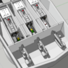
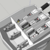
Another project is consuming me is building the Missouri turret offered by Takom with a full interior extending down into the barbette. The model is just an empty box. I'm drawing all of the machinery inside and it's the most challenging SketchUp project I've ever attempted on many levels. Just finding out how big things are and how they relate to each other is a big jigsaw puzzle. Here's what I've done so far. Remember: the externals will be in the kit, everything else will be 3D printed or scratch-built in some combination.
I have a puzzle to solve. Perhaps one of you guys has the answer. There are 8 compartments in the turret forward part: 1 on each side housing the manual aiming stations, 3 gun rooms and 3 compartments that lie between the guns where the powder hoist operator sits. But… there are only 6 doors/hatches in the rear bulkhead wall. So… how do the guys get into two of the gun rooms?
The two smaller doors left of center and the to right of center are the entrances to the powder hoist control area. The two doors at the extremes go to the manual aiming stations. The center larger door goes to the center gun room. So… how do you enter the left and right ones? I'm working with the curator of the USS New Jersey battleship museum and am going to ask him. He's committed to having the model displayed there when it's done.
Till next time.
Attachments
Myles, I knew you were still with us since I saw a few posts of the Seahawk build over the last while on Facebook. It does look extremely complex and delicate as you told us. Superb looking.
I'm glad the Covid restriction has been lifted so you can get in and get the parts for the hardware house cut soon. We are here when you get started. Welcome back!
Glad to please Mark!
I got the answer to my question from Ryan the curator of the USS NJ museum. The two side gun rooms are open on their outer flank. The doors at the end of the bulkhead lead to them AND to another compartment more forward which houses the manual aiming stations. It was hard to see this on the floor plan drawing I have. I think I'm going to do the landscaping on the Rick house site today…. finally! I've had the tracks near it covered in masking tape for months and want to run some trains.
Actually worked on train stuff today. Several things. First I repaired the nickel silver trim on the front of my 3rd Rail Pennsy S-1. This appliqué had broken loose before and I tried fixing it through non-solder means. It didn't hold. I ground away the surface to get new brass, clamped the very-springy piece back into position and soldered it with the RSU. I then found a brand-new bottle of acrylic Pennsy Brunswick green, masked the trim and air brushed to finish it.
I then backfilled the foundation area on the rick house in preparation for ground cover. I again use Sculptamold mixed with some W-S earth tint. I dampened the dry STM so the new wouldn't have all it's moisture sucked out before it set. I had previously wrapped the entire building base with Press n'Seal to I wouldn't get wrecked during the landscaping activity.
Lastly, I was given a Korber kit in payment for some of the 3D printing I did for a friend at the hobby shop. It's their General Power and Light office building.
I'm going to make it the Pennsylvania and Pacific Railroad's main office with appropriate signage on the roof. It's not a particularly sophisticated kit, and I'm using it as a time-filler until I get all the stuff done for the hardware store. I needed to pick a spot for it. There are three possibles.
The walls are a tad warped and I'm reinforcing them with some serious Plastruct "steel".
Till next time.
Attachments
The S-1 looks good! I like either of the first two locations for the P&PRR office. I wouldn't put it in town, thinking you would want to reserve that space for a nicer scratch built building. You were looking for ideas for structures to occupy some of the space between tracks anyway.
You are absolutely right. My first bought was to put in the space between the tracks in the back. that's where it will go. It will need an access road, and instead of running the road across a series of switches all set at an oblique angle to the proposed road, I think I'll just cut a highway tunnel under the high line and make a short road with a nice 90 degree RR crossing over a single track. having the RR's main office between the rails makes sense in a "model railroading" sort of way.
I like the idea of the highway tunnel so vehicles wouldn’t have to cross the tracks.
On second look, I may not have to do the tunnel. It's only one oblique track that needs a grade crossing. I can bend the road so it comes in at a more 90 degree angle (like prototype RRs do) so the crossing will look more natural.
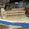
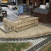
I got the ground cover on the Rick House site yesterday. I used some beigey paint that I had mixed for a wall repair. It was a light earth color. I then sprinkled a mix of W-S brown fine ballast and light turf, giving a less brown raw dirt look.
After pulling all the tape this is what it looked like. Not too bad. Some STM needed trimming where is bled under the building when being applied.
It needs some TLC on the slopes near the tracks such as some weeds and long grass. I can add most of this from the aisle edge of the layout. The area near the street can only be reached by scooting under the layout and coming up in the open space between the bridges.
An aside: My physical in November had my weight up to 184, my blood sugar at 104 for the first time in my life, so my internist suggested that I lose some weight. He said, maybe 175 was a good weight for me. I didn't like my weight! Clothes weren't fitting anymore and it was just unhealthy. I went on my kind of diet. I analyzed what I was doing differently that added the weight. When we moved to Louisville in 2009 I was at 193. I was FAT! It was years of business travel and lunches in the corporate cafeteria, plus, plus… I went on a diet and went down to 175. It held for a while, but over the last four years, it was just creeping up. Every trip back East added 3-4 pounds, and I'd lose two, and there as a new set point. It was caused by these factors: portion size, seconds, too many little deserts, more wine, and more lunch than I needed.
So without changing WHAT I ate, I adjusted how much I ate. I reduced my portion size about 30%, cut out seconds, stopped eating carbs at lunch, limited my wine to one modest glass, and have much, much less desert. I'm now at 174 and I want to go further. I'm technically overweight by the BMI until 169. I haven't weighed 169 since the early 80s. I'd be happy at the low 170s.
So why am I wasting your time with this drivel? Here's why! I was dreading going under and on top of the layout because it was getting harder to do. I thought it was my AGE. It wasn't! It was that extra 10 pounds around my waste. Yesterday, getting under by sitting on my scooter and climbing up to layout height was easy. It felt really good! Another benefit. I just put my belt on the fourth hole holding up my jeans. I've never had that belt on that hole since I bought it years ago. It had gone from the 3rd hole to the 2nd which was the wrong direction. It's now going in the right direction. I still exercise regularly on the recumbent bike and elliptical. So eat less move more! A diet plan in one sentence. I have not changed what I eat. I was already eating pretty healthy, but I reduced how much of it goes in. It's chemistry.
Now, back to the Rick house.
I put the building back in its slot. Needed some adjustment, but not bad from the viewer's side of the layout.
It needed some added STM around the loading dock and the rear facing the fire house.
There is a problem! When I checked out the street side, the building is not sitting down to ground level and I'm not sure why.
You can see it looking up the street from the layout's front, but not easily. Not sure what to do about this. I'm going to wait until the newly applied STM is cured, pull the building and see if I can find what's lift it. Stay tuned.
I'm debating building a chain link fence to surround the construction site. Not sure if it will add or detract from the scene. I have a the big billboard to install and will put a light on it. I also need to add some wood piles, and make a batch to hang from the crane's hook. I have to add some construction workers around the site to liven it up. End is in sight.
The
Attachments
Myles, the 90 degree turn in the road sounds good. You are right, it is quite common near railroads. I occasionally drive through an area that has two 90 degree turns, between two railroads with a grade crossing over one and a one lane underpass onset the other. There is a bridge over the creek that flows between the two tracks that the road parallels for 100 feet. It would be a neat scene to model.
Congratulations on the weight loss. My story is similar, and I am 10 to 15 pounds over where I was 10 years ago when I lost 35 pounds. I have been working on more exercise and less food.
Mark, we all know that losing isn't really the battle. It's keeping it off. The percentage of people who maintain their weight is quite small. The problem with reducing intake is you're no longer as satisfied (full) as you used to be so you add a little here and there and Poof! you up 10 pounds. We have a dear friend who is very, very overweight. It's affecting her health with orthopedic breakdown. She needs to lose 100 pounds. It seems so daunting, but I would be if she reduced her intake by 20% a day, she'd slowly start to lose. It would take a couple of years. Her weight prevents her from exercising which creates a vicious circle. Move more eat less. If you can't move more then you even have to less than less.
I got rick house to settle down more so the gaps on the street side are now decent. I touched up some of the areas missing ground cover, planted the sign and brought in the rental crane. Those deals are expensive so you have to keep them working. Still have more details to add which I will be doing from time to time. Forgive the soft focus...
I did more work on the P&PRR office building. You have to file off all the flash on the resin casting. I also had to re-scribe the end bricks on the big walls since these are on the outside of the corner joint and show up. I'm going to 3D print a sign to go over the front door. I took it outside and repainted the walls since the cleanup exposed a lot of bare resin on the various edges. I use my go-to Rust Oleum Red Oxide Primer. I still have to grout all the brick lines. The weather was great today for an outside spray activity with a light breeze and 66 degree temp.
The brick lines on the end were very shallow to start with so I used a triangular diamond-coated needle file to rebuild them.
Attachments
The Rick house looks great on that site! The crane really makes the scene. Are you going to put stacks of lumber around it too?
@Former Member Just found this post. Work looks good. I have the Korber building and have thought about putting it together. For sure on my next layout, but mine has a lot of warp to the walls. Did you heat it up to flatten out or just use backers to straighten the walls. I also have the lack of brick lines in places and will probably have to file the ends out like you are doing.
Oops - just saw the I-beams you are using to flatten the walls.
Yes! I’m going to put lumber stacks and make a sling of some and hang it in the hook. Got some construction guys to decorate the place. Still on the fence ( no pun intended) about making chain link for the site. The figures were intended for the machine shop and would have needed repainting. Since they’re actually supposed to be construction workers I can use as is.
and yes! As you saw, using stiffeners to straighten walls. Adding a bases plate between the walls and a Masonite (instead of cardboard) roof will help also. Maybe a floor or two as well.
Yesterday's work...
prepped the walls by scribing where the joints would fall and where all the reinforcing 1/4" wood would go, and scraped off the paint so the CA would be sticking to resin and not paint which isn't so hot. I glued the roof ledges on, more stiffeners to take out the remaining warpage, and started gluing the sides together.
I marked a place for a first floor plate too. This was to take out the warp and provide a light block so I can illuminate the lobby floor independently from the rest of the building. I'm going to selectively block out various windows so it's not just a four-story building with all the lights on. I'm going to use some strip LEDS that I bought last year for this job.
I have an ancient Dunlap picture framing clamps that was my dad's that held the bottom corner square and a corner clamp that held the top, and then used various quickie clamps to squeeze the remaining joint into contact. I pushed and pulled the mating edges so they were in perfect alignment before applying any thin CA. I pretreated the area with CA Accelerator so it would cure quickly.
I glued the opposing corners together. Next session I will glue the adjacent sides together forming the full building.
Joint areas prepped for gluing;
Adding the 1st floor ledge again using some serious Plastruct H-beam that will serve double-duty: straightening a warp and providing a place for the floor plate to sit. I glued the roof ledges in before joining the walls, but held off adding the corner reinforcement until after they were joined. I couldn't be certain of how the corner joint was going to fall if I glued the blocking in early. After gluing the corners I added the blocking with more CA.
The two wall sets are ready for glue up on Monday. Adding floors also helps remove any additional warpage.
I 3D printed a raised-letter plaque for over the front doors. It fits into the recess that already molded in. Being so thin it only took 17 minutes to print. If I upgrade my Elegoo Mars original to the new Mars 3, I could print in 4 minutes.
First coat was some Pennsy Tuscan red. I will go over all the raised areas with gold. I have a gold Sharpie marker that should pick out the raised areas pretty well. I may have to pre-coat with clear lacquer so the alcohol-based marker won't dissolve the acrylic base paint. Took 10 minutes to draw this on SketchUp.
Attachments
The plaque for over the front doors came out great!
Work continues on the P&PRR HQ building. Got the rest of the floor ledges installed, cut the various plates for the floors, etc., and put the lighting together. As complex as my other projects have been, this one is pretty simple with very few embellishments. I may spend some time on the roof and some big signage, but that's all post-building.
The kit's roof plate is a piece of cardboard. I don't like that. I'm making it out of Masonite along with the base plate and the 2nd floor. This is the bottom. I have trouble cutting nice square pieces of sheet stock because I don't have a table saw and am too lazy to set up fences and use my circular saw. I laid out the lines and cut it with the saber saw. Unfortunately, the edge that I was measuring from (which I assumed was square) was not square so I have to so some creative sanding on the belt sander to make it reasonable. The bottom plate came out really well.
The building was not yet glued together in the above.
For Lighting, again, I'm going easy. I have these sheets of 12VDC LED lights that I get from Amazon that are used to light outdoor signage. They're in series and need no current adjustment. Just pump 12VDC into them. They're very cheap. The already have double-sides foam tape on their backs so mounting is a snap.
These put out a very yellow light. I bought them as "Warm White", but they look really warm to me. I don't care. It will resemble lighting in an old incandescent office building like back in the day. The yellow lead is +.
After soldering I use some shrink tubing to protect the connections. I'm using some old light-gauge zip-cord that's really old. The copper is degraded and took a longer time than normal to tin. Most folks don't know this, but copper conductors can oxidize even inside the insulation jacket. The jackets are gas permeable over time. Silicon insulation is better, but vinyl/rubber doesn't hold up forever.
Here's what the light looks like on the first floor test.
And here's the lights looking directly at them.
At the end of the session I got the building glued together. I also painted the text on the raised letting signage for the front door. Next up is building all those window sets.
Attachments
I agree with you, they really do look like warm light. I think they look good as incandescent light.
In a shortened session, I did get started on building up all the windows. They are installed as assembled pairs.
Here's what it looked like at the start.
There was a little flash on the upper edge on about 50% of the plastic (Grandt Line?) parts.
To build the double window, first I had to remove the little bit of window sill on the mating surfaces. I cut them off with the #11 blade and then sanded them square on the precision Sander. I chose to do this one assembly at a time to avoid more boredom. It's an assembly line kind of job and not very creative.
Progress at the end of the session. I will probably finish this today. I use the steel weights to hold the assembled frames flat while they cure. All of these will be painted and glazed BEFORE installing in the building. When the frames are done and while the paint is drying I'll be applying the grouting to the brick work. Some of the windows will be randomly blacked-out so it looks like some are at work and some are not. (maybe working virtually due to COVID ![]() ). I'm assembling the frames on the bare Corian which is dead flat and unaffected by the solvent cement. My cutting pad's getting a bit worn and has all kind of lumps stuck to it making it no longer flat.
). I'm assembling the frames on the bare Corian which is dead flat and unaffected by the solvent cement. My cutting pad's getting a bit worn and has all kind of lumps stuck to it making it no longer flat.
Attachments
That is a lot of windows, now that I see they are installed in pairs. I know what you mean about cutting pads. After a while they are no longer flat.
There are 54 of them to be exact at 110 singles. There are exactly the right amount which is troubling because one of them was molded funny and I would have tossed it, but I need it. Any funky windows (for whatever reason) will be on the back wall facing nobody. I made a big dent today, again having a late start because of running errands and quitting early since it was "Cocktails Friday". My wife and I established this tradition during COVID lockdown when I learned to make a mean Vodka Gimlet, Lemon drop martini and a great Old Fashioned. Couldn't go the bar so I brought the bar home.
During today's work I had to do a repair to my True Sander. Fighting the thumb screws were pulling the permanently mounted fence upward. This created a gap under which the movable fence was moving putting it out of square. I couldn't tighten the screws any more and tightening them was the cause of the problem in the first place. I drilled and put in three metric machine screws, nuts and washers pulling the bar down tight and in the right place. I had to counter-bore the back since a) my screws weren't very long and b) they needed to be recessed anyway.
This finally fixed an annoying defect in this product. This is my 2nd True Sander, but the first one didn't have this problem.
Everyone have a nice weekend. The temp in Louisville is going to go to almost 80. We'll pay for that. I can imagine some significant weather as a result.
Attachments
All the windows are assembled and painted. I used Badger Model Tech paint UP Armor Yellow in keeping with the overall theme of the RR. I stuck them all to some corrugated and used the airbrush. Took two coats. We're going on a two-day trip to Champagne IL to visit #1 grandson at U of IL and will be back in the shop on Thursday.
I took a beauty shot of some equipment in preparation to make the billboard.
I removed the Background to enable me to substitute something.
Attachments
That's a handsome lineup suitable for framing!
Have some Champaign while you are in Illinois.
It took over an hour to pose them. Some of them haven't been run in over a year. I had to replace three traction tires, use contact cleaner on the rollers and clean some track. Then I had to jostle them around to free up track. I only had to carry two of them. O'gauge trains are more forgiving regarding dirty track than our DC operating brethren, but there is a limit.
Back from visiting U of IL's campus and grandson. It's a vast place like Michigan State's is. All these land grant colleges tend to have enormous campuses. The engineering campus alone was bigger than most smaller colleges. He's doing quite well and has a nice apartment just off campus sharing with four roommates. It's in a high rise, is a two-story affair with two bedrooms downstairs and two up. Each has their own bathroom. Not like it was in the old days. Nothing on a college campuses today was like it was in the old days. They're pampered! His building has a gym, pool tables, movie theater and a BOWLING ALLEY (two lanes to be exact). Yeah! That's just like it was when I went to MSU… not!
Myles,
I'm late with this but can you provide a link to or show a more focused photo for the LEDS you purchased from Amazon?
Thanks,
Dave
Wow! Your grandson’s college is certainly not like what Slippery Rock was like 50 years ago!
Sure is! Here's the link to the LEDs
Back to work. I got to exercising a bit earlier today which gave me a full work session too. Got the windows glazed. The kit came with 6 sheets of acetate that needed slicing and dicing. I measured the assembled frame and used the digital caliper as a marking gauge. I cut the long strips with a #11 and long steel rule.
The glazing pieces were square so I set up the Chopper 2 for the short side cuts. I wanted to gang cut them five at a time, but the Masonite Chopper base is bowed downward, so the middle strips were moving all over the place. I added a piece of illustration board to the fence's underside thinking it would fill the gap better, but it didn't work well. I ended up cutting two at time holding the strips on each end. I also found that the left side barrier is no longer square to the cutting clamp while the is okay. I'm making sure to put the sliding fence at that edge.
I cut a lot of these suckers.
I used MicroMark Pressure Sensitive Adhesive (PSA) to secure the glazing to the frames. I talked about this stuff before, but it's so useful in these applications that it's worth repeating it. It's water-soluble when liquid, but when cured really only comes off with Goo Gone. It dries clear, tends to stay where you put it, and lets you glue glazing in with very little fuss. It does not cloud or attach styrene or acetate. It works best when the liquid dries and loses any white color. Once it's clear you're ready to go.
I put a thin film on the glazing surfaces on the frames doing them five at a time. By the time I coated the last piece, the first was ready for the acetate. In this example you can still see some white liquid indicating it's not quite ready for the glazing. I you glaze too soon, you run the risk of the adhesive to ooze out onto the viewing surface and it's not as strong.
Here are all the windows with glazing. A ton of windows. I'm glad the building wasn't any deeper or taller. It gets boring...
I'm going to airbrush the inside of the glazing with some flat clear so they're opaque. I'm not planning on doing any interior details since it's 12 feet from the viewer, so frosted windows are called for. I'll do that tomorrow. I used the same taped boards to re-attach the windows for the flat coat. The white styrene strips in some of the frames serve to reinforce questionable joints and help to flatten some that had too much bend when they cured.
I didn't need all the glazing that I cut. Here's what was left over (enough for another building it looks like).
I didn't toss these. Acetate is hard to come by and you can always find a use for more window glazing.
Till next time.


