Have faith. I'm learning this stuff as I go. I've built models for 60 years, but I've never built a railroad with scenery before. That's what the Internet is for.
Rather than starting to plaster cloth the ravines, I decided to work the entire topographic treatment around that entire end of the layout. I made this choice based on difficulty in imagining how to transition the scenicked area to the untreated area. By establishing the terrain for the whole area made it easier to visualize the total look.
I then realized that fascia boards needed to be fitted to provide an anchorage for the scenery that extends over the edge of the layout. So I bought a 25' roll of aluminum screening from Lowes. Also from Lowes I bought two 4 X 8 sheets of green extruded polystyrene, one 1/2" and the other 3/4". This will be enough to get started on the basis for the city.
The hardest part of this whole job is getting into the between-the-ravines space. I have to use my scooter to propel myself under the layout into this space. I'm leaving this space open so all areas of the layout are reachable except for the center of where the city's going to go. I still have to figure how I'm going to handle that.
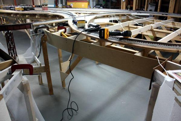
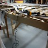
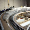
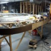
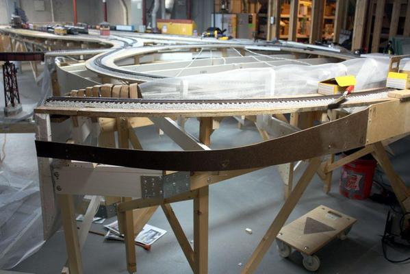
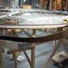
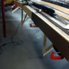
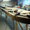
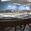
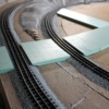
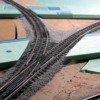
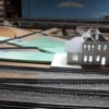
Here're some shots of this area with their fascia boards in place. I'm thinking I'm going to make the terrain height the same as the joists which would add more interest coming off of the track level. It's one of the advantages of building with L-girder and using shaped sub-roadbed pieces—being able to build below-track-height areas as easy as building elevations above.
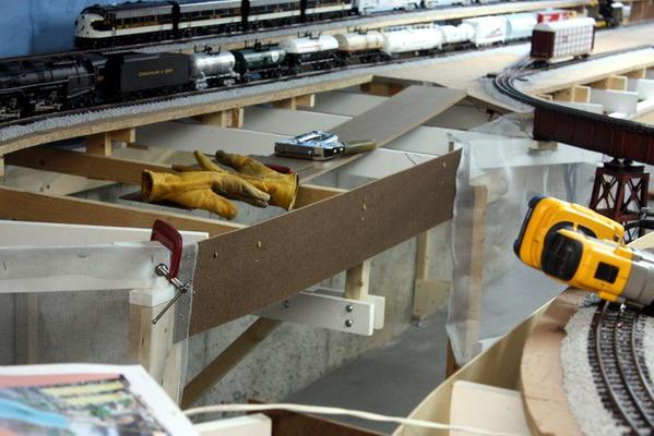
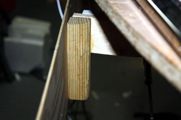
In this case, the screws holding the fascia are put into the joists end-grain. I'm not particularly happy about this, but these boards won't be bumped or touched very often. On the outside of the layout, I'm adding blocks to the joists or joist extensions for the screws are holding in cross-grain. The above picture also shows the depressed area next to the track that will be landscaped at that level.
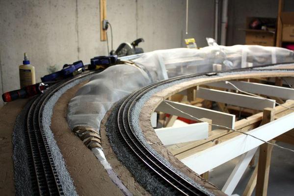
After putting in these boards, I went back outside and built the screen framework for the terrain that lies between the left-end tracks. I'm going to sculpt this area so the outside will be a cut, with bare Kentucky limestone strata, and the inner-face with a more gradual, nature land-form. To push the screen up more on the outside I quickly cobbled together some cut Styrofoam "beams" hot-glued to the layout framing. Again, you have to use Low-temp hot glue for bead board. Normal hot glue is too hot and melts holes into the foam. This is from experience.
Once the plaster cloth is added, the lumps will be worked out. This screen is not for strength which comes when layers of plaster impregnated cloth or paper towels hardens. Scultamold will then be applied for texturing the rock face. I've got good pictures of the rock formations that I'm modeling and probably won't need too many rock molds. Kentucky rocks don't look like that.
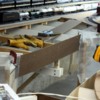
While the screen was being applied, I was letting joist extension and mounting blocks the chance to dry. In most cases I'm gluing the extension, not screwing them since they don't handle much load and Titebond joints are stronger than the wood when properly clamped during drying.
I have many feet of fascia board that's already prepared with junction plates that were used on the last iteration of the layout. In fact, I had just installed all the fascia boards when I was laid off, decided to move and had to disassemble the whole thing. There are extra screw holes since these pieces are no longer in the same place. I'll fill those holes before painting the boards.
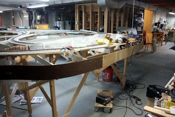
As the fascia bends towards the foreground is another area where the landscape will gradually taper down from the edge. Further around the curve the edge will drop straight down. While I'm not happy with that, It gets into an area where aisle width get narrow and I can't afford to make the layout any wider.
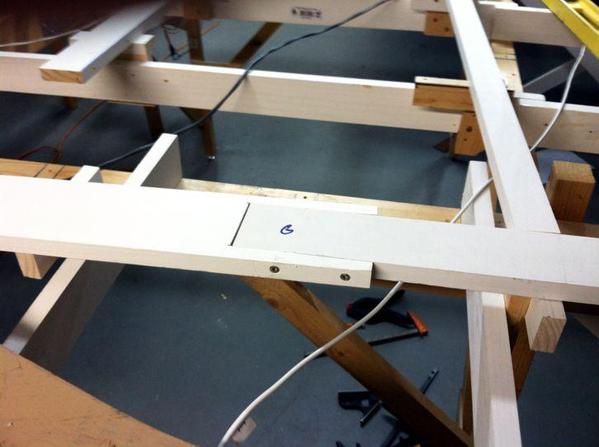
Here's one more shot showing how the fascia boards are fastened to the layout
All these little extensions and mounts help use up a lot of odds and ends in the wood scrap box.
Attachments
As I was lying in bed last night and thinking about what's coming up next with the layout—being retired and in reasonably good health, thinking about the layout project is what occupies my mind—I realized that I put the fascia boards on wrong. I was mounting them at the level of the lowered landscape area near the ravine, rather than level with the platform. This left a 2 inch gap between the top of the fascia and the layout top which would have been ridiculous to fill.
So the first thing I did today was to rip it all out and remount it at table level and then using the saber saw, cut out the area that would be landscaped lower.
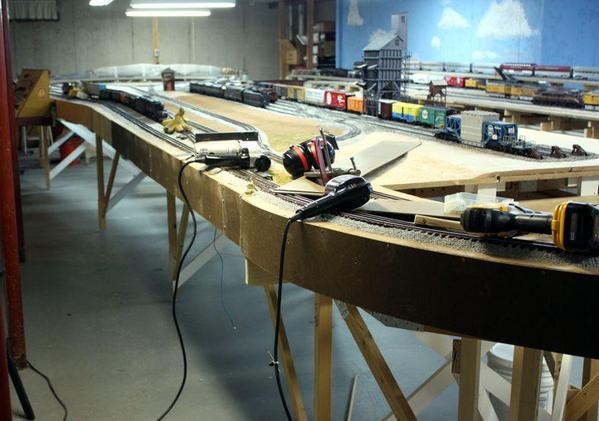
This change also made it much easier to attach the boards since they screw directly into the panels edge. This was going so well, I decided to do the fascias all the way around. Again, I have lots of boards from the last layout, and even though this layout is 11 feet longer, since I have 39 feet of it against a wall, I have enough to almost complete all exposed edges on this layout.
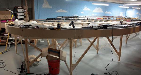
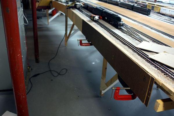
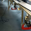
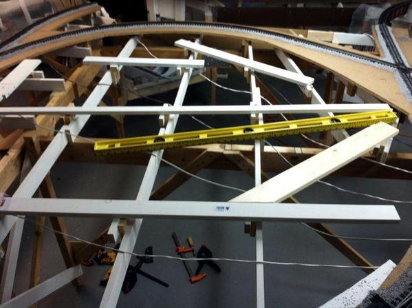
Since I'm doing this build mostly alone, he's how I hold the boards in place so I don't need three hands (or more) to align the pieces for drilling and screwing.
A large C-clamp fastened to a joist and then a smaller one set to support the boards at the correct height. It works nicely and makes the job go quickly. Individual boards are joined to each other using a backing plate glued to one side and 3mm screws, nuts and washers holding the mating piece. Metric sizes are because these screws were purchased when building layout #1 in Germany.
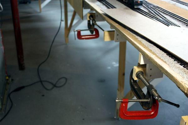
Here's the right end. I had to trim the piece slightly at the swing-gate to make sure it closed completely.
After all the boards are in place I'm going to mask the layout and track and spray with a nice deep green. I have some paint I used before, but I might by new low-odor paint so it won't smell up the rest of the house. The forced-air heating system is just leaky enough on the intake side to suck up any hobby smells from the basement and send it all over the place.
Resetting the fascia height meant that some of the supports that I glued on yesterday were now hanging below the boards. The saber saw made fast work of them.
The layout immediately looks more finished without those joist ends stick out all over the place. There's plenty of holes in the boards from when used in previous installations. I'll fill them before painting. The fascia board also adds a convenient place to add any local controls for more switches, and/or any operating accessories.
Attachments
What a spectacular layout and read! It took me well over an hour to read this thread from start to finish but well worth the time.
I congratulate you on your attention to detail. I will be following this thread to see how it all turns out.
Thanks! It's fun to write about it also. I found out about doing detailed build threads on a Scale RC aircraft website where some of the finest modelers in the world detail their construction projects. As much fun as it is seeing the finished results of peoples' handiwork, there's much more learning to be had by seeing how they did it. The swing gate idea was the direct result of input from Clem on this thread. There's many more...
Did you go back and read the platform construction thread in the Layout Design forum? If not, it gives the same level of detail on all the steps to build a large L-girder framework.
For those of you who would like to start at the beginning I am posting the link to the platform construction here!
Trust me the platform building and this thread are great reads and very informative
https://ogrforum.ogaugerr.com/t...-build-thread?page=1
What I really want to know, and keep asking myself is, "Where was this creativity and attention to detail when I was a freshman at Michigan State in 1963?" Somehow between then and becoming a senior citizen it came about. There's still hope for all of us.
Not only that, but throughout my education I hated to write. Had a terminal case of "white paper syndrome" and froze when looking at a blank page. I previously (on another forum site) did a 13 month thread on a model battleship build. Someone suggested extracting it and creating an eBook. So I copied the thread into MS Word, removed all the back and forth commentary and just had the pictures and text of what I was doing. It came to over 300 pages! If anyone would have suggested when I was 18 that I would be writing 300 pages of detailed descriptive text on a model project, I would have thought them to be nuts. If I only knew. Youth is definitely wasted on the young.
I haven't published the eBook yet because I have a railroad to build.
Finished putting the framework in that will support the city and then marked and cut the thin Masonite. This material is quite old since I believe I purchased it to build the n-gauge layout with my son before he went to college (it never got past the L-girders) and he's now heading for 39. It's amazing that almost every scrap of wood that I dragged from our old house is slowly being incorporated into this new RR.
There's 3/4" dimensional lumber running across the cleats. I also added more cleats to span areas that I thought would be too broad for stability. I still have to add some brackets around the perimeter to support the thin material and foam around the edges. For some reason, the cleats kept coming out at different heights. I was taking all level measurements from the first cleat I installed, but there must have been stacking errors creeping in since some cleats were more that 1/8" higher than they should be. I was up and down on the scooter more times than I'd like to count.
I was using every scrap of lumber I had and didn't want to got to THD to buy more. So I had to extend on board to span the gap I wanted.
I flopped the pieces of Masonite onto the framework and aligned one edge to keep the amount of cutting to a minimum. From underneath I marked the circular shape of the opening using a Sharpie. The saber saw with a fine-toothed blade made quick work of the cuts. I had to go back and re-cut some of the curves due to the parallax induced by the gap between the curve and Masonite.
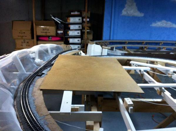
Here're the pieces in place... not fastened.
All the pieces are cut and reasonably fit. Now I have to figure out the best way to fasten the Masonite to the support network. I want this 'sub-floor' to be fastened tightly, but the foam on top will be removable so I have build scenes off the layout and bring them to it when done. It's over 7 feet across and much too far to reach, and is not as strong as the layout and wouldn't support someone walking on it. Too much concentrated load would punch a hole right through this stuff.
Tomorrow I will finish up fitting these pieces and then get them into permanent position. As I'm writing this, I'm thinking that I'll mark the position of the support structure on each panel piece from under. Take the pieces off the table and drill holes for some small wood screws in the center of the framework marks and then return them to the frame and screw it down. Since these screws will be hidden, it would make taking the layout apart some day more difficult, but if the foam is detachable, they won't be so hidden after all. I also need to join the panel pieces together. Here again I'll use screw plates underneath made out of some thicker stock and put the screws in from above.
Once again, taking time to write this build thread helps me think through challenges.
Attachments
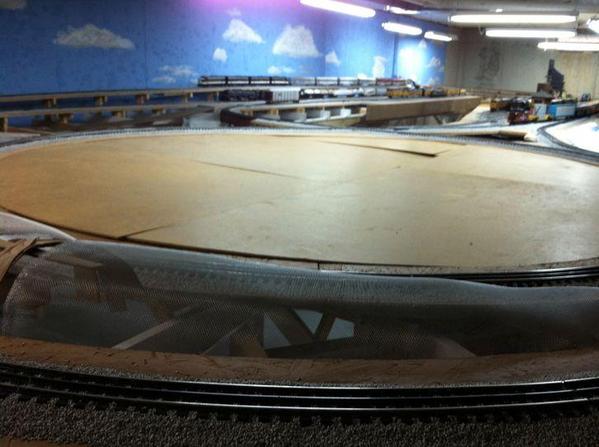
I completed final fitting and screwing down the Masonite city foundation. It was the hardest thing I've had to do on this layout in a long time. It involved scooting below and climbing above multiple times. While the Masonite's not strong enough to walk on, I was able to lean on it when I was directly over the underlying framework. I did find some particularly spongy areas that I will go back and reinforce.
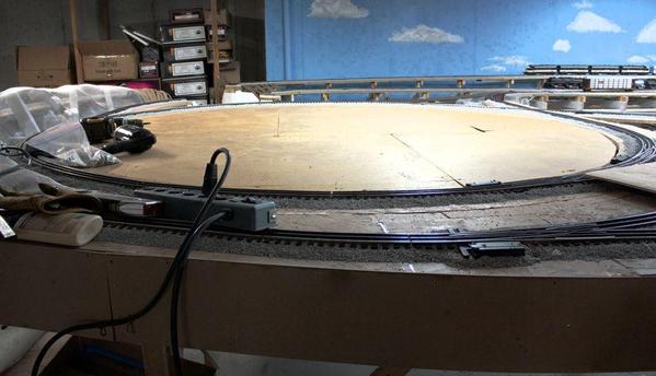
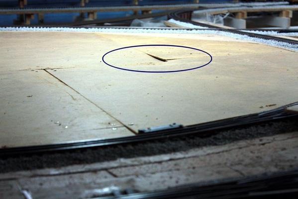
There's a couple of areas needing some more attention, one which is circled in this next shot. There seems to be a depression in that area that I'm going to see if I can level it. I'm also going to firm up the spongy areas so if you do need to lean on it, it won't break through.
I shot these pictures with the Canon Rebel. The last few days I was using the iPhone 4. I'm getting a 5s on Monday which has a superior camera. I may be able to get away using the phone for all these shots. The above picture also used the photo stitch software to make a deep depth of field. My problem with the iPhone is holding it steady. My hands aren't too steady and after handling the DeWalt XRP, they're even shakier. The Canon has image stabilization and for the depth of field shots, I use a tripod with a 2 second time delay so no shake.
I also need to fasten a splice plate beneath this are since I spliced next to it, but missed all the corners.
Next session I'll start cutting and fitting the foam. I'm thinking about creating a fixed perimeter of foam around the curves, with the inner pieces removable. This is necessary since the perimeter's going to need not only fixed, but landscaped pretty significantly. The weekend's here and my deal with my major supporter is "no trains on the weekend".
Attachments
trainman...I am surprised you didn't make a lift out in the middle for your grandson or you to gain easy access to your town area.
your making steady progress any hopes on seeing a video of trains actually running?
$oo
You're the reason why I spend all the time writing about this... giving me inspiration and thoughts that I haven't had. A lift out... Hmmmmm. It's not too late for that. L-girder is flexible enough to make modifications at this time. I'll look at the structure and see what I can come up with. I have to separate some of joists a bit so it's easier to get up through them. As it was I was able to stand between them if I did so carefully.
Trains have been running but are stymied now by the bridges being out. I was going to plaster the ravines so the bridges could be installed right away and get the trains running, but now I'm glad I've chosen to flesh out the city area since I would have been banging into that plaster all the time. I've bumped the screen wire between the tracks more times than I'd like to admit, but without scenery it doesn't matter.
so now that your percolating on a lift out how about using a separate piece of 2" pink foam board for the hatch cover then you only have the weight of the building or? to lift out of your way.
I myself have a 12' area for a town and intend to use the same foam for it as well.
am I mistaken that you can bypass bridge area seems like there was a wye or a line heading for the yard area or am I mixed up.
apparently your agreement with better half didn't include the ogr forum! can you hear my laughter. haven't heard you mention grandsons for awhile are they still helping you with the layout?
$oo
I like the idea about the 2" foam, or I could laminate a piece of Masonite with the 3/4" stuff I have and not have to buy any more foam.
The Forum doesn't count since "I'm not in the basement".
Grandsons are swamped with school activities, including after-school sports for both. We're watching them both nights next weekend so maybe I can get some more work out of them. There's lots of ground cover to be put down on the finished areas of the layout.
If anyone watches "Parenthood", there's a sub-story running right now that really strikes a nerve. One of the couples has an adopted adolescent boy who's having trouble reading. The school wanted to let him back for 4th grade, but the father is upset about that. The grandfather, meanwhile, (Craig T. Nelson) has purchased a 1966 Pontiac GTO fixer-upper. He cons the youngster into helping him out, but he has to read the repair manual in order to do it right and the kid's learning how to read. When I was teaching power technology in inner-city Philly in the late 60s, I kept a supply of Hot Rod magazines in the room. I didn't care what they read as long as they did it. I often said as an industrial arts teacher, that with some kinds of kids, if I had them all day, I'd teach them all their basic skills in the context of working with their hands and making things. I stand by that thought today. This is the way the guild system worked in the old days. You worked with the master and he not only taught you the craft, but he taught how to manage the business. Maybe we should have some of that again.
Really little. It started before they were two when I used to run Train Simulator on my laptop. Alex used to love to blow the whistle. When the 2nd came along (2.5 years later) he too liked the Train Simulator. When the trains were finally built in Pennsy, I immediately let them couple and uncouple cars, follow the trains around, and touch anything as long as "Grandpop" was there to guide them. By the time they were five, they could run the controls. I had some loose trucks which they liked to shoot back and forth between them. We also did that with some sturdy cars. It was easy to do then since the layout had no scenery to get in the way.
We would also build lots of other stuff together including Legos and K'Nex. I also play video games with them and show interest in what they're interested in.
This is the same way I worked with my son and daughter when they were that age. I was building Pocher 1/8th scale model cars on commission. I was building three-at-a-time on the dining room table so there were cars and thousands of parts just sitting there. So whenever I was building, I would sit my son down next to me—he was just over two at the time—and give him some pieces to fit together.
I also had a part that both kids did. The vinyl tires were very thick and stiff and if you tried to put them on the wire wheel rims cold, the rim would disintegrate. So we had to heat them up in hot water. So one kid would put them in the water and one would take them out and then I'd build the wheels. Whenever I started a new batch they'd be asking if it was time to make the wheels yet.
In other words, and I apologize for this very long answer to a very short question, I've always believed that kids can touch things with supervision.
Now the kids major work is to put down ground cover and plastering.
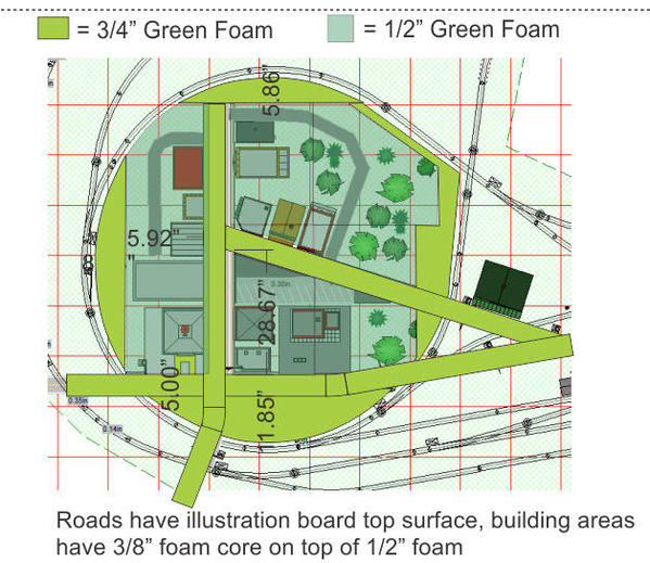
It's time to really understand how the city's going together. I have 2, 4X8 sheets of green foam, one 1/2" and the other 3/4". One sheet isn't enough to pave the entire city area that's now covered with Masonite. Rather than buy another—I may still have to to do mountain construction—I've concocted a scheme to use both thicknesses to some advantage.
My buildings are all mounted on 3/8" foam core. If I use the 3/4" for the streets, and the 1/2" as a foundation under the buildings, what results is a very nice curb between the street and sidewalk. I plan on surfacing the streets with illustration or Bristol board, so the actual height difference is about 8 scale inches which is very nice. In this way, I'm maximizing the use of both kinds of foam I have and solves the problem of having the streets at a slightly lower level than the surrounding construction.
I'm using 5" width for the streets. That's 20 scale feet which is a pretty narrow street. I could make them wider. Does anyone have suggestions about city street width?
In looking at some other folks pics I realized that my original design wasn't making the best use of the space since I have the main street receding into the distance perpendicular to the front of the RR. I re-positioned things so there's a main street running across the face. The gas station is on a base that is exactly what mine is, but the rest of the buildings are right out of RRTrack and are representations of what I have. I had to position the streets so they crossed tracks away from switches. I will also have to make a "rock cut" on the left side where there's now a hill between the tracks. Notice that all the grade crossings are on curves which makes their construction much more complex.
This is another example of bringing in a screen print from RRTrack and using CorelDraw to design a scaled working drawing.
Attachments
Wonderful job. I enjoy following your progress.
Peter
just a thought have you considered raising the town area and spanning tracks with bridges?
as to street width it depends as to how much area you have. so do you want space to allow for parked cars at curb as well as a driving lane?
if not you can get cars approximately 1 1/2-1 3/4" wide so use that as a guide.
might be only me but I would think the roadway at lower part of drawing could be omitted only my opinion its your layout to do what pleases you true.
$oo
The original design had the city elevated withy trackage below, but both grandsons nixed it due to their height deficiencies. I tried to convince them that their height was just a temporary condition that would be resolved in a few years. They didn't buy it and insisted that I build the city at track level. This simplified a lot of things for me especially creating the retaining wall that would surround the entire city area. It would also eliminated some tricky hidden switching operations.
Without the street across the front... what would the foreground buildings front against? I'll take suggestions and/or diagrams. I haven't cut any foam yet—will do that tomorrow—so I can change darn near anything as long as it fits in that 7 foot circle.
There's a lot of surface area in that space (39 ft. sq.) so it might allow for some nice sized city streets. It also would use up more of the 3/4" foam and make my 1/2" go farther.
Today I reinforced the soft areas under the Masonite and the entire area is now ready for more stuff to go on top.
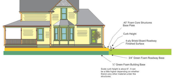
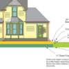
Started cutting lots of green extruded foam making the main streets that run through the town. I drew up a section view to show how the various thickness stack up to make the streets, curbs and a foundation for all the structures.
That house on the drawing is a 1:48 scale drawing that I made of an old Mainline Modeler HO project. It's a lovely little house that works perfectly for my railroad, and it's a scratch build project I'll get to someday.
The stack gives about a 6" curb height which I like since most model railroad curbs tend to be too high.
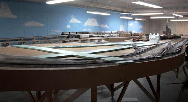
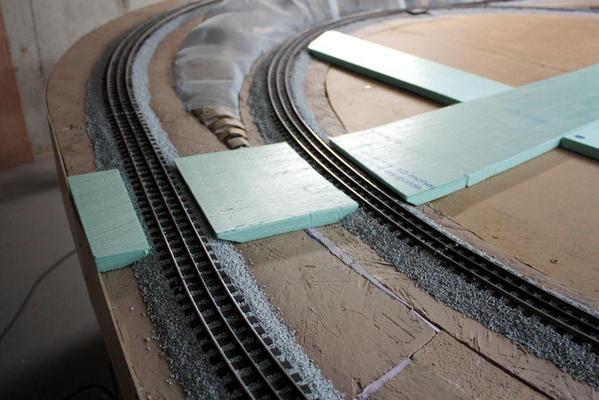
I cut all the streets and got them positioned. Here's what it looks like.
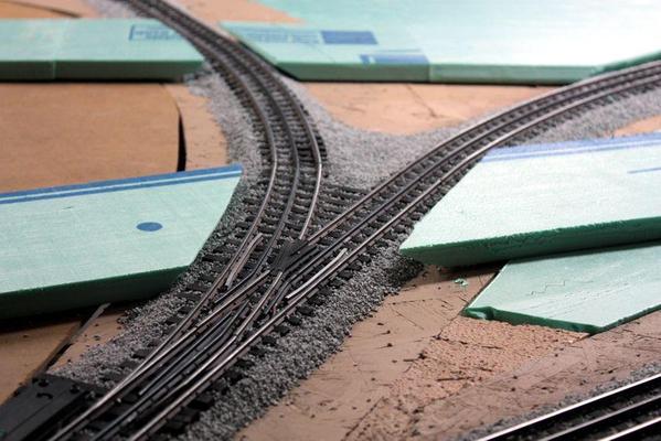
Everything's working out as planned, but there are a number of grade crossings at curves and even over switches that are going to be a bear to build. You just can't throw a couple of stripwood planks down and call it a crossing. I'm going to take to Steve at Ross Custom Switches to see if there's any way he can help out. I'm especially concerned about creating good flange ways. If I come up with a good way to make a barrier for the flange way, I could use plaster and mold the grade crossing. I could also cut them out from balsa. In fact, as I'm writing this, I think that might be the best way to attack this challenge.
I'm also looking at these pictures and realized I wasted a lot of time beveling the underneath of the road pieces to nest into the ballast. It would have been much easier to just remove the ballast and sub-roadbed where the road approaches are. In fact. I'm going to go back and do that, and then add some new piece of foam to get very close to the track.
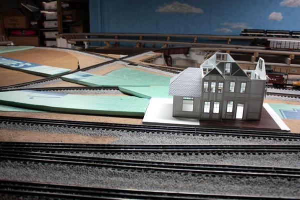
There are two streets converging on the train station. The station is raised on a piece of thin foam core, and some illustration board to bring it up the same height that the road. There will also be a parking lot next to the station.
The pieces of foam at glued together with the low-temp hot glue. On top of the foam go 4 ply Bristol Board that I just purchased at Michael's crafts. It was pricey. It cost as much as the foam. It will be adhered to the foam with 3M 77 spray adhesive. Then it will be painted and have line work painted on. I also want to install man hole covers, storm drains, potholes, and other street-like things.


