That is one project I dislike; glazing windows. When I modeled in N scale, I just didn't bother with glazing at all. With much younger eyes, I didn't miss it in N scale. I'll have to get some of the MicroMark Pressure Sensitive Adhesive (PSA). Thank you!
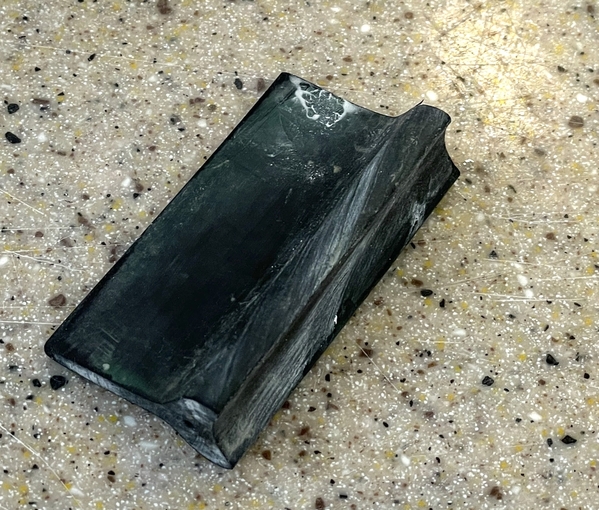
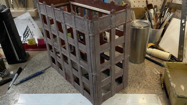
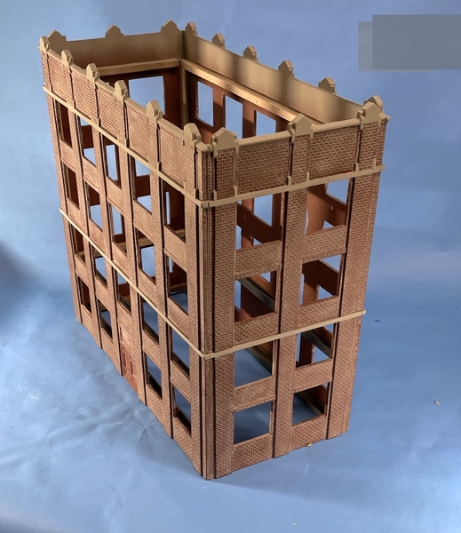
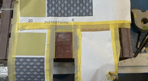
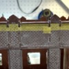
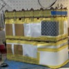
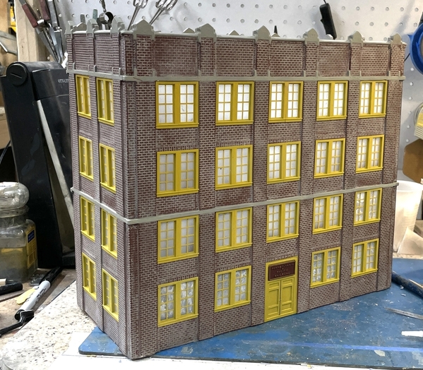
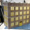
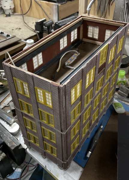
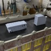
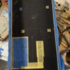
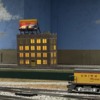
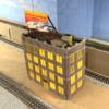
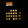
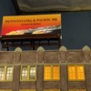
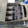
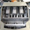
All I did yesterday was spray the flat on the inside of the windows. Most came out good, some not so good. If the coat was too thick it laid down some pretty opaque white patches. No problem. Any sub-par windows will be on the side facing the wall. I just have to keep that in mind as I move forward. When I took this image, the flat coat wasn't completely dry which accounts for the reflections you're seeing on the ones to the right. It was those wet spots that dried funky. The windows will be sufficiently frosty to diffuse the light and obscure the interior.
Attachments
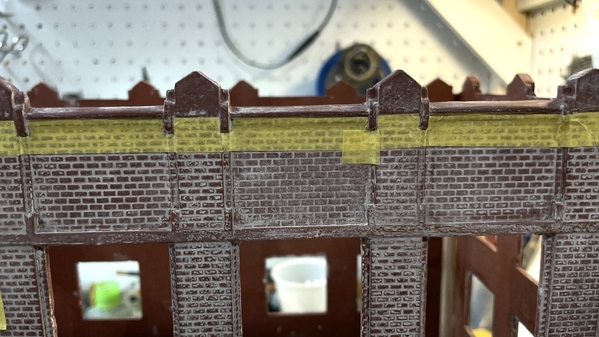
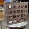
Started adding mortar to the bricks. The building has a many levels of brick work greatly complicating putting mortar lines in. I first tried some house hold latex wall paint, but the results were terrible. I went back to my Joint Compound method that I've used several times before. I added some Mars Black tube acrylic artist paint to make it more gray and overdid it, so I knocked it back with some white paint of the same type.
This little bit is all the compound I have left. I have to get more at the hardware store.
I was first slathering it on with a palette knife and then using a single-edged razor to scrape off the excess, but changed by putting a blob of the joint compound at the start of the area getting mortar and using the razor to squeegee the "mortar" down over the area which did the spreading and scraping in one operation. I then used a #11 blade ground to a broad/flat edge to remove excess in the corners of all the various height areas.
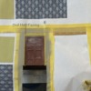
I finished one side in about 2.5 hours. It's a slow, annoying process, but it makes a huge difference in the ultimate appearance of the model. When I do the hardware store, I'm going to paint and mortar the layers before I glue them together making it go much faster. When this part is done, I'll use an alcohol wash to dull it down a lot. There are masonry and top details that will be concrete color. I will mask and paint them when all the mortar work is done. The molded-in door will be painted the UP Armor Yellow window color. If I was going to leave the windows clear I would have to put in floors and a core with elevators and stairwells. The building is so narrow that a core almost wouldn't actually fit.
Attachments
Very nice looking. Worth the effort!
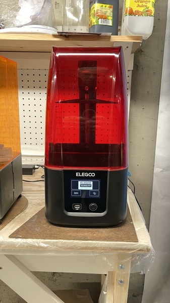
Haven't worked on the building due to getting more supplies, errands, picking up family at airport etc. Did get a new Elegoo Mars 3 printer. It's 4X faster, and about 30% greater volume. I'm going to run it along with my original, picking the more complex and larger jobs for the new machine. The new one has a 4K monochromatic LCD instead of the 2k colored screen in the original. This means much higher X-Y resolution, better pixel definition and greater fidelity. This is coupled with a significantly brighter UV LED Light system. Each layer will take between 1.5 and 3.0 seconds versus my old one at 10 seconds. I got it all set up and leveled today. I need to set up a separate profile for this machine, and keep them identified so I don't try and use the wrong one on the wrong machine. The price for this machine was the same as the Mars 1 in 2019.
The design is much more refined than my Mars 1. In three years the technology has really advanced. Everything about it is more elegant and more slickly designed.
This machine couldn't have come at a better time with the massive print job needed to produce the parts for the Missouri Turret. My hobby shop wants me to print more parts for the store.
Attachments
Finally got all the mortar in place. Developed another new approach on Friday that sped up the process a bit. I'm using the flexible rubber edge of a contour sanding tool. It's rubber and worked as a squeegee to spread the joint compound without damaging the paint below. The razor blade occasionally scraped to deep and removed some brick red paint.
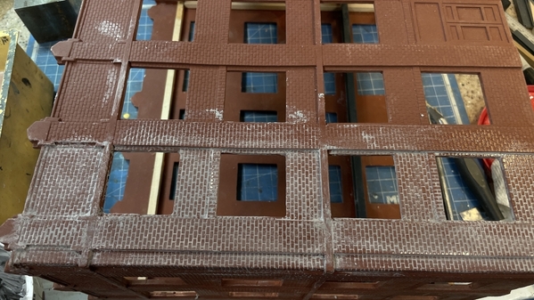
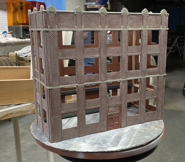
So here's the mortared building, although you can only see two sides. Take my word for it, the other two sides are done also. I will probably seal all this before applying the aging solution.
Lastly, I am now the owner of another 3D printer; an Elegoo Mars 3. It's got 30% more build volume, 4X faster exposure, and a 4K monochrome LCD with 8 times the X-Y resolution, than my "old" Elegoo Mars 1 (Classic). It's already going to produce great parts for the turret project. For example: I can print the entire officer's compartment floor with the rammer machines attached in one piece. My old machine wouldn't fit it. And it will print this in five hours instead of twenty. I'm keeping the old for non-critical jobs or thin ones that will print quickly.
The new machine is much more refined than the first generation. Elegoo has come a long way in less than 3 years. They've sold a lot of printers and got a lot of feedback which they incorporated.
Attachments
The mortar work looks great!
Miles, after doing a bunch of brick buildings with the lightweight spackling mix, I finally had great success cutting up old credit cards and used them both to apply and remove the excess mortar. They have about the perfect flexibility, they don't cut and scrape the brick facing, like metal blades and I made up several widths depending on the brick pattern and layout. I did the Korber Pickle factory as a long flat and with custom cut putty tools I was able to get in to the recess brick areas and use the plastic cards to both apply the mortar and very effectively clean out all the inside corners really well.
Old credit cards is a terrific idea. I'll try that on the Hardware Store when I start doing it. I have to make the reservation at the U of L's Bakery to use their laser cutter.
I spent three days masking the concrete trim work (sandstone?) on the P&PRR HQ. It was finicky working around the various indentations and details. The lower band was simple being straight across, but the upper band was a completely different story.
While it took days to mask, it only took about 10 minutes to airbrush my concrete mix (Tamiya Deck Tan plus a little black).
I sprayed the insides of the parapet with the same color. I will then mask it part way up and spray with Tamiya Rubber Black to simulate the tar weather-proofing that will protect the area. The roof itself with be tar and gravel.
With the trim done, it was time to mask and paint the front door (on both sides). I got one masked before the workday ended. I will paint this the same Armor Yellow that I used for the windows. And then I'll then mount the signs over the doors.
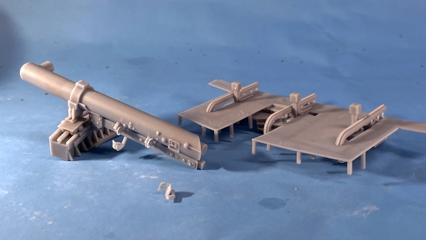
While this is going on I was working on the Missouri Turret Project (multi-tasking) with the new printer. The printer is terrific and I lover the 4X speed. The larger capacity is letting me print large pieces in one part including apparatus already attached. This is going to save a lot of fussing during assembly. Here are some examples:
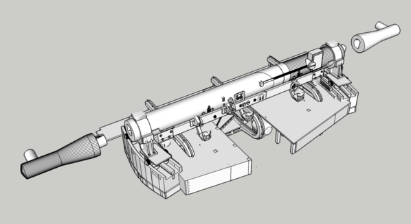
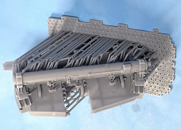
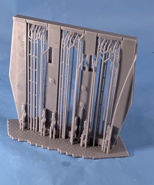
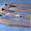
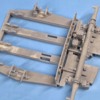
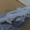
This shows the entire officer's compartment floor with the steps, legs and all three rammers installed. The other object is one half of the complex long-base rangefinder that runs across the entire turret out out the ears protruding from the sides. Note the little seat that broke off when I was removing the supports. This new found ability will mean that I may be able to print the entire electric deck with the myriad of machines on it as a single part. You can't see it in this image, but there's a perfectly formed gear rack inside that curved surface.
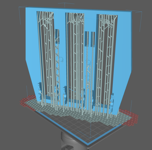
Here's how I'm going to print the massive gun-girder assembly. At first I was going to print it with the manual sighting station equipment attached, but changed the scheme based on some good input. I'm now printing it with the bottom half of the guns lugs in place. I will be able to drop the guns into the lugs and attach the top caps. This part was too tall and wide to print on my Mars Classic. The part of the base extending out of range probably won't matter. If it doesn't print well, I'll split the part into two halves and do it again.
Like my first printer arriving just in time to make a huge difference in the Engine House project, this one too arrived at the perfect time to make this new and complex project possible.
Attachments
The masking and spraying certainly was with the effort for crisp definition between the sandstone and bricks!
Working both the turret project and the P&PRR HQ simultaneously. Got good progress on both.
Installed the fancy signs over the doors and made a dent installing ALL those windows. In some cases I had to file the window openings to remove any errant joint compound so they fit without stress. I'm using Gel CA to hold them in. I pre-shoot the opening with accelerator so the gel cures quickly. I hold the windows down to insure they're nice and flat while the CA cures. I still have to create the graphic for the top billboard and design some roof details which I will 3D print. This is the backside of the building and has the windows, that didn't frost so well.
I ran into a turret problem. The long-base rangefinder wouldn't go into the plastic gun house part without cutting the walls below the kit's openings.
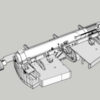
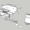
I was having trouble with the officer's compartment floor print anyway, so I chose to re-design the whole deal into a since printed part. I fixed all the floor problems at the same and create a perfectly aligned construction. I put the two halves of the tube back together and split the tube outside of the support structure. I make the tips with keyed attachments so they would go into properly.
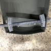
And here's the result. The hand wheels formed perfectly. I just have to careful removing the few supports around them. I use heavy supports for the whole model and then go back and substitute light supports on any part where removing the heavy support would destroy the detail. If you look closely at the RF base structure you'll see perfectly formed gear teeth in the traversing rack. "If I can think it, I can probably draw it. If I can draw it, I can print it. If I can print it, I can make it." Support removable is the hardest part of the whole operation.
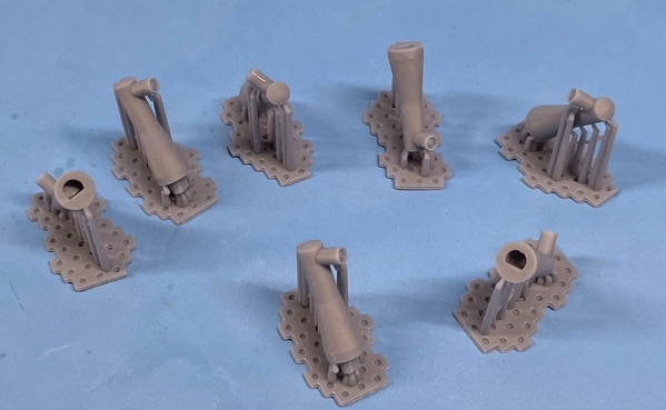
And the tips.
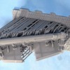
I also solved another problem by printing the entire gun girder assembly with integral gun grunion lugs. I was originally going to fabricate this assembly out of sheet styrene. This was so much more substantial and ELEGANT. This is just about the largest part I can print in my new machine AND it already exceeds the size capacity of my cleaning system. By printing perfectly vertical, I only needed supports in the horizontal print areas.
The trunion bores are perfectly in line. I was originally going to make the guns movable, but realized today that this would only work for the one gun in the firing position. The other two will have the loading cradle/spanning tray protruding into their breaches. If you attempted to elevate the gun, you'd break the cradle assembly (and that would be bad!).
I've said this before, but it bears repeating. The arrival of my Mars Classic coincided with the creation of the engine house, and the arrival of the Mar 3 makes the turret project possible. Creating the myriad of tiny highly detailed and technically complex parts without 3D printing technology would be beyond my skill set and I wouldn't even consider it.
Attachments
Both projects are looking great!
Myles,
I love the window color on the building. It looks great.
when I see the things you do with the 3d printer, I feel like John Henry building the railroad by hand against a machine. It’s funny how things stick in your brain from childhood.
Great work Myles
Thanks guys. Al, I may be asking you for help and/or advice in the battleship turret project. I need to make six cylindrical (or slightly tapered) drums representing the outer walls of the interior levels and the exterior armored barbette of the turret stack. In SketchUp I'm able to take a shape and unwrap it and flatten it. If makes figuring out what the actual shape of the conical cylinder is without the drudgery of doing an old sheet metal layout project (which I used to know how to do and have long forgotten).
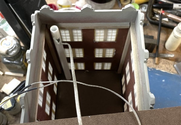
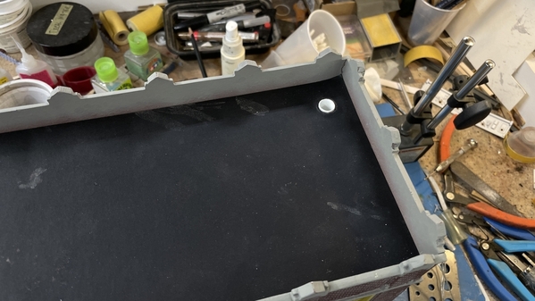
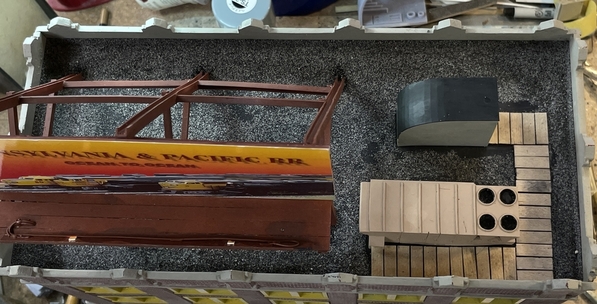
I got all the windows into the P&PRR HQ building, got the ceiling of the first floor installed with its lighting and am about to put in the base plate and roof plate. I've drilled all three pieces of Masonite with a 1/2" drill to accept a piece of ABS tubing of that size to act as a wire chase to bring all the lighting to the "basement". I'm also going to build the bill board and light it.
Here's the upside down view of the building with that ceiling in place.
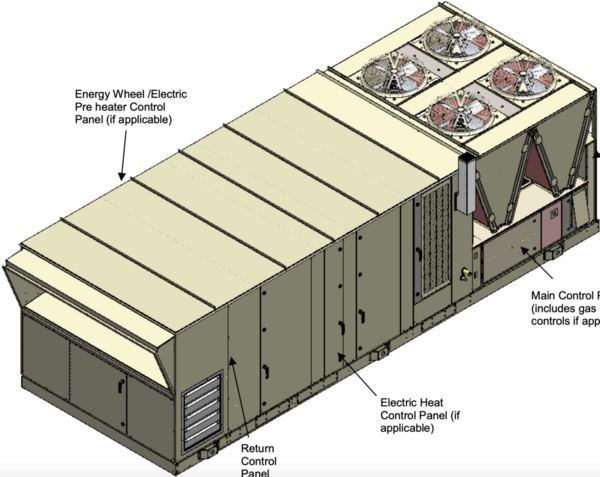
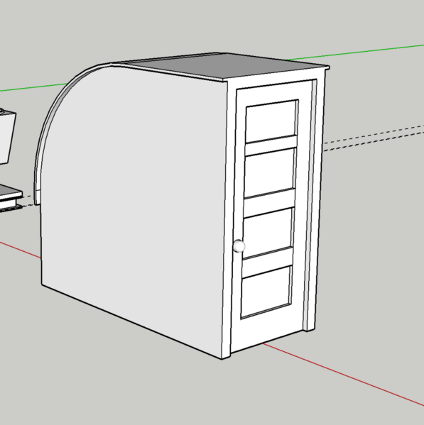
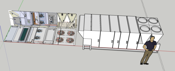
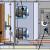
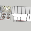
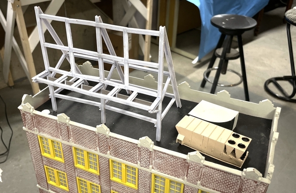
I took a few minutes and drew a commercial HVAC unit and a roof stair exit to add some interest to the roof. With the drawing experience I'm getting with the turret project, this one literally took just a few minutes. I was able to download an installation document for a Daikin unit and use the drawings and dimensions within to draw the HVAC.
Since this building is far in the background, (10 feet away) I didn't go crazy in detailing the AC unit. For example: I didn't attempt to detail the fans.
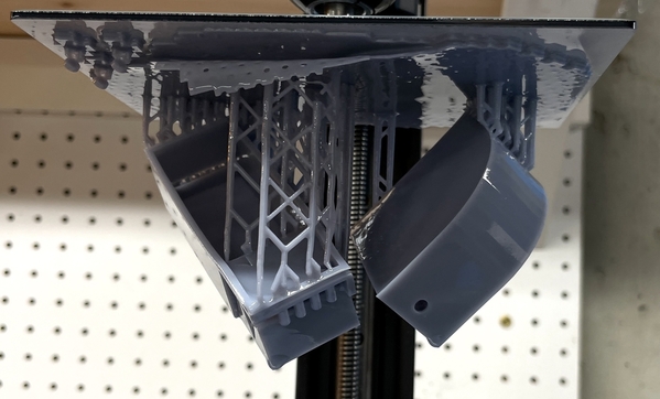
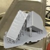
I printed them yesterday, but didn't get them off the machine yet. The hole in the stair enclosure is a drain hole. I used the "Hollow" feature along with "Drill Holes". On a massive print like this one, you can either open up the bottom and hollow it out that way, or you can have the slicer program actually form a hollow inside. You need to have a way to let out the liquid resin that was not hardened in the print process, thus you need a drain hole at the part's lowest point and an air inlet hole at the upper part. What you see is the drain hole. I don't use this feature very often, but for both of these I used the programmatic method to do it.
I forgot to add some structural parts under the condensers on this side of the part. I will add them old-school with some styrene angle.
I'm also going to try and print the entire bill board frame as a single part with the new printer's enlarged capacity. So far… the new machine has been flawless.
Turret update:
My gun spacing is wrong! A fellow forum follower sent me some actual measurements. The real gun center-to-center spacing is 10'-2", mine came out as 9'-5". This error was causing me problems in getting the doors on the back bulkhead to line up properly, and, more importantly, my guns weren't lining up precisely with the kit's plastic gun house part. It took four hours to make the drawing changes, and get them ready for re-print. I wastes some resin, but at least I have the capability to make the fixes myself.
It's a shame because the rangefinder/floor print really came out pretty good. The optical tips on the rangefinder are just placed there. They won't be permanently attached until the gun house is built. The 6.88" (1:1 scale) change affected the main gun girder foundation, the back bulkhead door spacing and the spacing of the rammers on the officer's compartment floor. That meant redesigning the floor itself and fixing some more troubles it had, and I don't think the floor is right yet. There's another access aisle on the right side that I don't know where it goes.
And here's how much debris is created when to extricate the big rangefinder print from the forest of supports. It took almost an hour to cut it away and clean up the print. Even though the machine puts all the details in, you still have to trim it all up without wrecking anything.
Lastly, the metal gun barrels arrived yesterday which was a surprise. I thought it was going to take much longer. I was then able to accurately measure the diameter of the joint end of the barrel and modify the big gun slide assembly to perfectly match it.
It's going to be sweet when those guns are built even if I don't have the rest complete yet. I don't know of anyone whose created and accurate 1:72 scale 16" gun in its entirety. Lots of army field pieces, but not of a big naval gun like this.
Myles, none of the photographs are showing up for me.
I was interrupted and the post timed out. Here's all of yesterday's pics, plus some from today.
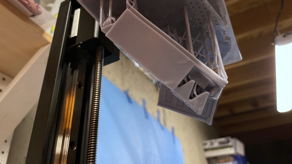
Today I pulled the roof prints, clipped off all the supports and it's now in the Post-cure chamber. Using the Hollowing feature worked well and reduced some of the resin needed to build a high volume part.
I also got the conduit tube finished and have it installed in the building.
I'm reprinting all of the turret parts that I corrected and some that haven't been printed yet.
Attachments
Now a roof HVAC unit is something I never thought of putting on a building. Of course, all of my builds are intended to represent 1955 or earlier, so Iwhy would I have thought of it? Nice work!
It is my role in life to provide inspiration to others...
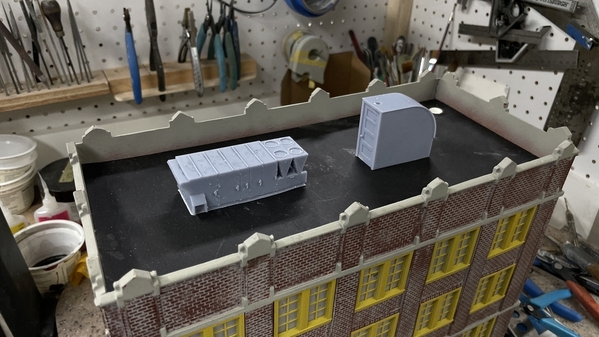
There was some warpage in the AC unit, which if I were to make more of them, would fix with more wall thickness (I took a lot of material out of th bottom to save resin) and some inner bracing, but I'm not making more of them. It will work fine viewed from the great distance. Here's the two add-ons being checked for fit on the roof. The roof door looks a little oversized, but not really. I scales to 7 feet tall.
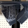
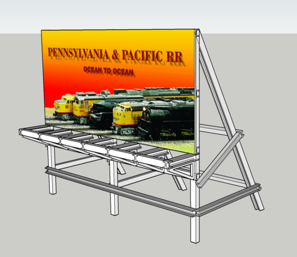
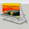
I designed the billboard and set it up for 3D printing. My original design of 7" wide was too big for my even-larger printer. I reduced it to 90% and it just fits. I was going to try and print it in one piece, but that didn't fit so I broke it up into subassemblies and will print it next week. I think it's overbuilt, but it's designed to handle Kentucky tornadoes.
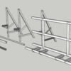
Here's the breakdown for printing. The three angle braces are one print, and the rest is another.
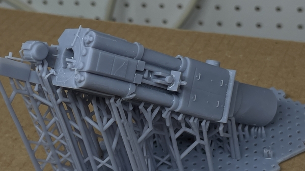
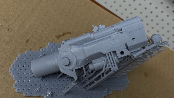
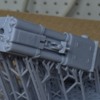
On the turret front, I successfully (sort-of) printed the entire gun slide assembly. It was successful because the details were superb. Not-so-successful because it warped and the gun, while fitting perfectly, points askew. Even the lifting handles resolved on the counter-recoil cover.
I tried using the "hollow out" feature on the slicer which opens up spaces inside objects to reduce resin use. You must provide opening so any uncured resin can escape. I did all this, but was unhappy with the results and it may have contributed to the warpage. All the stuff around the breach resolved nicely including the coil springs on the breach counterbalance. The breach weighs over 800 pounds and is opened with the help of some air cylinders and springs.
From the side, the gun looks great.
From the top, not so hot.
After hours of redesign, I decided to split the slide portion, make the breach yoke a separate part, and provide a means to screw the halves together giving a bit more control than gluing them.
I'm using some massive (in this scale) screws and nuts to assemble it. it's what I had in the shot. So I drew some plugs that will fill the holes after it's assembled. Due to the nature of the turret, you may only see the flanks of the one of the guns on the end depending on where I put the transparent parts. It will take five print runs to make parts for three guns. The first slide set is printing now and will be done at 7:00pm. Another change I made is to re-size the trunion pin so I can use a piece of 1/4 aluminum rod as the pin. Again, the re-draw showed some errors in my original that I'm glad I fixed before going ahead.
I also got a beautiful print of the massive ring gear that is an integral part of the turret. The top surface is the lower race for the roller bearing that support this 2,500 ton beast. The turret weighs as much as a destroyer. The four segments key together since I couldn't get a full ring on the printer. Prototypical I might add since the rear one was built up of segment too. So far the new printer has been flawless. The changes Elegoo has made on the finish on the build plate has produced no separations during printing. And the higher resolution and print speeds are all pluses. So of the details I'm getting on this project wouldn't have been possible on my Elegoo Mars Classic.
Attachments
@Trainman2001 posted:It is my role in life to provide inspiration to others...
Yes, I would say that is a true statement!
I think the HVAC unit and roof door look great! They will be an enhancement to the building. I think the 'overbuild' on the roof sign is warranted. I've seen what tornados can do right here in Butler County.
Those turret ring gear part do look fantastic!
We're almost getting done here...
I got the lighting and window blocking done. I also printed and built the billboard frame. Regarding 3D printing the billboard frame, it worked… but...
The but is warpage and flexibility. While it's going to work fine, upon close examination it a little rough. These pieces were the largest my new printer is capable of. The pieces were so high that when complete the lower end was still sitting in the resin vat. It's also bigger than my cleaning vats.
The new printer has been flawless. As usual, any mistakes are traced back to my drawings. I've pretty much figured out how to apply the supports so they don't fail. Any parts of the job that have significant mass I use exclusively heavy supports. On small details or areas that are claearly small I use light supports. I rarely use medium.
Here's a front and back view of the structure. Since I took the pictures, I planked the catwalk. It's a little bigger than I originally imagined, but it will be so far away that the size is an advantage. There's not much room left for the stairs and AC. BTW: I painted those yesterday. I made a mistake in NOT bringing the SketchUp drawing down to the shop with me. As a result, I ended up gluing it together improperly. The lower member on the front under the catwalk really belonged upwards to support the back of the angle brackets. I ended up added some stripwood to replace these members.
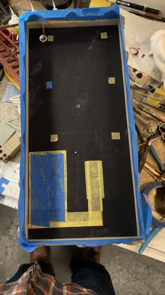
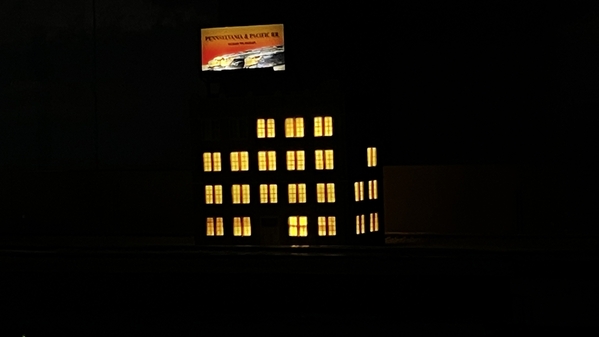
Here was the building with the lights on and the windows blocked. There was some leakage and when I opened up the roof, one of the panel's sticky stuff had let go and I fixed it with some electrical tape. I like to have some offices dark just to break the monotony.
I printed out the signage today and cut a piece of 040 styrene. After painting the entire frame with the sign backing, I will attached the size with some adhesive transfer tape or the Pressure Sensitive Adhesive. This building will be finished next week. I'll have to do some road and parking lot work on the layout to support it. Plus crawl around underneath to tie the new building into the layout's utility grid.
Everyone have a nice Passover Seder, Happy Easter or Joyous Ramadan whichever is appropriate.
Attachments
Very nice update Myles! The billboard frame turned out nice.
Dave
@Trainman2001 posted:I like to have some offices dark just to break the monotony.
Yes! Thank you. IMO, nothing ruins a large building model more than having ALL the windows uniformly illuminated.
I totally agree that buildings need to have 'some rooms with the lights off' to look realistic! The billboard frame looks great.
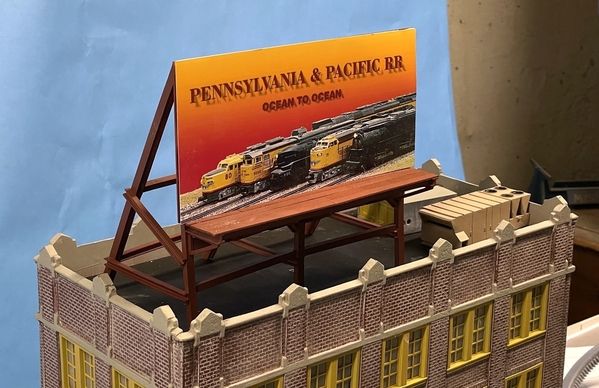
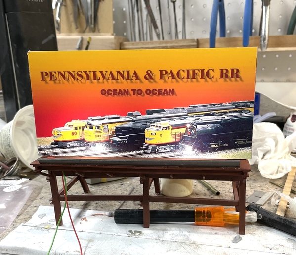
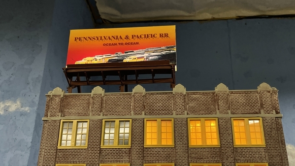
Glad you all agree. I got the billboard painted. The sign's not adhered yet in the pic. Just there for show. I'm going to have to fab some spot lights for it, because my idea of using the strip lights below the parapet would cast a big shadow upwards due to the catwalk. The width of this building, while very convenient for fitting tight spaces, is ridiculous. The stairwell/elevator shaft would take up most of the width with very little space on each side for aisles and offices.
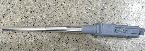
On the turret front: after four iterations of trying to 3D print the gun body that was a) not warped or b) not perforated in some way, I printed a perfect one today and followed it up with two more. One gun set is left-loaded and the other two are right-loaded based on which side the powder hoist opening is. To adapt the metal guns to the resin slide assembly I turned down the tail to 7/16" so I could had the slide end narrow enough to fit through the turret openings while still having enough meat to support the guns. The only details I lost were the teeny tiny hand grabs on the counter-recoil covers. I will replace them with fine wire. The "bad" on the gun girder print is because there's some new information that required a re-design. I'm printing another in the next couple of days.
I had some trouble with the drawings of the open breach version of the Yoke (the heavy back part that houses the breach. I was also able to successfully use the "hollow' feature of my slicer to open up the interior to reduce resin quantity and help with the warpage. Notice too I am using a 1/4" trunnion shaft instead of printing the trunnion integral with the rest of the model. The length of the nose extension will be adjusted once I have the new gun girder part in hand and have the kit parts to fit it to.
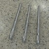
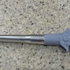
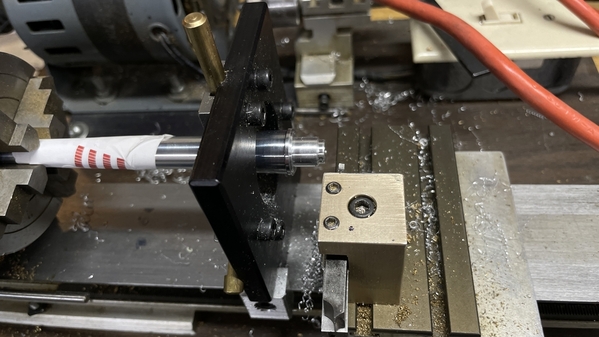
Chucking the tapered barrel into my little lathe required some careful handling. I wrapped the part of the barrel that would be grabbed by the four jaw independent chuck, and then used a steady rest to support the huge overhang. The overhang was the result of having a lathe with a very small through-hole in the spindle. It took 10 minutes to true the one I was doing today, but I got it within a couple of thousandths and was able to accurately turn the new diameter.
Attachments
@Trainman2001 Beautiful work - I have that building for a place on my next layout. Seems to me many O town/city buildings don't have good proportions relative to the prototype. That one looks pretty narrow front to back. But if it had more depth where would it fit on a normal layout?
Are you making battleship guns? I missed your earlier post so I know the answer, but did you remove some of you images or are the powers concerned someone will print your turret for nefarious purposes.
One of these days I have to learn 3D printing. Started to learn autocad, but never had a consistent use for it so I kept forgetting commands.
The billboard is looking very nice! Yes the building is narrow front to back, but since you said it is at a distance from the viewer, it will look great!
I had written a great answer to Scouting Dad's question, and just lost it all because I didn't post it last night. First of all, the Valejo paint required two full days to fully cure. I had mixed it with Model Master Universal Acrylic Thinner and some Liquitex Acrylic Extender. Yesterday after 24 hours it was basically still wet… like get paint on your fingers wet. I got the sign attached to the backing yesterday using the 3M Adhesive Transfer Tape. Today I built a light bar to illuminate it. At first I tried to solder the tiny surface mount LEDs with the magnet wire to build some light fixtures supported by a 1/16" aluminum tube, but couldn't solder the LEDs without overheating and killing them. I did that to three of them. I then went back to my more consistent method which is soldering them to adhesive copper tape like I do for my building interiors. This is a much more predictable method since I don't actually put the soldering iron onto the LED. I hold it next to it and let the molten solder creep up to the LED.
I CA'd the bar to the front edge of the catwalk and put some power on it to see if it worked. It does. I will install a CL2N3 driver chip on the + end and will let it drop down the conduit tube so it will be out of sight. The gloss finish shows a hot spot from the lights, but I can't get around that. The bar will be painted with the same red oxide as the rest of the project. I'll be mounting the sign and finishing the roof tomorrow.
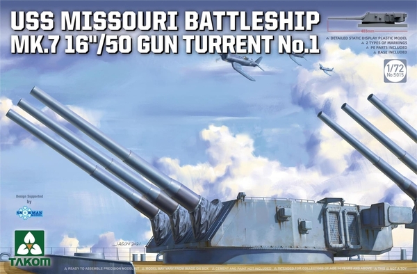
Now to Scouting Dad's question. Yes! I'm building a fully detailed USS Iowa Class turret #1 in WW2 configuration with the entire interior down five decks to the magazine level. The bare kit is the Takom Missouri Turret in 1/72 scale, but is just an empty shell of the gun house with plastic guns. The aluminum guns are a Chinese aftermarket product made for the kit, but I had to turn down the back end to better work with the 3D printed gun slide and yoke assembly that I designed and printed. About 70% of the interior will be 3D printing and I'm already into several months of drawing (and re-drawing) components. I've been getting help (as usual) from folks who read my ubiquitous build threads that accompany all my projects on various forums depending on the nature of the project. The kit looks like this.
The reason it's in WW2 configuration is the presence of the long-base rangefinder ears sticking out of the sides. That was removed from the #1 turrets on all the Iowa class ships during the 1980s refit. That rangefinder had a habit of ingesting sea water in heavy seas so it was a problem.
Instead of me going any further with this and hijacking my own thread, perhaps you can follow along in a detailed accounting on another forum found here:
https://forums.kitmaker.net/t/...t-to-finish/16832/44
I've been wanting to do this project for years, but the technology wasn't available nor was the kit that provided the starting point.
Re: 3D Printing: Resin 3D printing is demanding and difficult to just dabble in. If you're just going to print figurines or trinkets, you can get by by downloading existing STL files on the Internet and make stuff. If you, like me, want to create unique parts for models that are not on the market, you must not only master the printer, but you need to master 3D drawing programs as well. I've been a SketchUp user since ver. 1.0 and am very proficient, but there are others. I find that 80% of my printing failures are due to errors in my drawings, not the printer. That said, I remain available for anyone out there who wants to join the lunacy.
Attachments
Mighty MO Myles????? I think it was Christmas when I was 16 that I got the large U.S.S Missouri model as one of my Christmas presents. I spent the next couple of days painting and gluing that big monster together. I think it is almost 3 feet long, and dwarfs all the other battleships I had built up to then. Guns look nice, that's for sure.
My very first model on my birthday in 1954 was the Revell Missouri. It is purported to be the first model Revell made with their own dies. I started building it on the living room floor with Testor's Liquid Cement. It was in a very easily spoilable oval-bottomed bottle that tipped easily. I had the glue sitting in the box top. It spilled, I panicked and moved it to a nice piece of furniture sitting on a lump of Kleenex. It spilled again, this time taking some of the table's finish with it. I ran upstairs and hid, but my dad found me an it wasn't a pleasant experience. You'd think after such trauma, I wouldn't build another kit. Not so. I was hooked and built many, many kits as a kid. I had a brief hiatus after getting my driver's license, guitar and girls in that order, but actually started again in college realizing how much I missed it. My skills continued to evolve and now, heading into my late 70s, are still evolving as I take advantage of new technologies to apply to the craft.
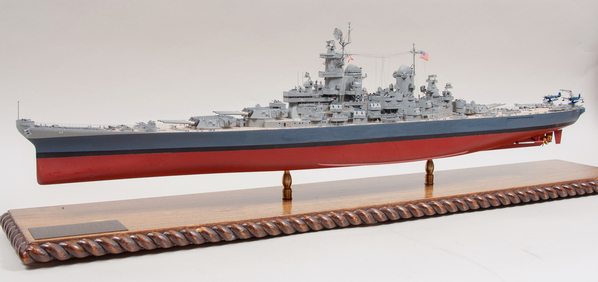
I built the Tamiya Missouri (probably the one you built) in the mid-80s just before all the after-market etched brass was available. Then I built it again in 2011 when my oldest grandson was in Middle School and into model building. This time I pulled out all the stops and added another 1,000 parts to the kit. I was rewarded with an offer to display it in the real Missouri's Captain's Cabin if I could get it safely to Pearl Harbor on my nickel. Three years ago, the ship won Best Ship at our local judged show.
This turret project will be pinnacle of all my ship modeling. I'm having to re-draw and reprint a lot of parts as I learn more about what I'm doing.
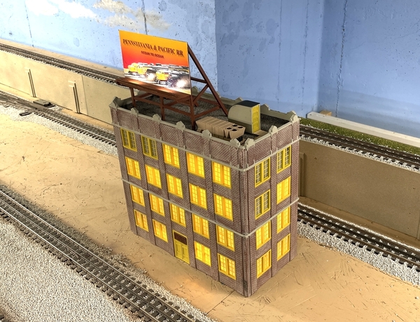
Onto the P&PRR HQ: It's finished and lit and on the layout! Yesterday I got the roof gravel on over a wet coat of artist's acrylic dark, dark gray. I masked the areas that were going to hold the stairs, HVAC, Billboard and plank walkway.
And here it is finished. I didn't put in vent stacks or other details since the roof is not visible from anywhere in the room unless you're 6'-6" or taller. The planks are Northeastern bass wood 2 X 12s tinted with an alcohol wash. I first was gluing the planks with Aleen's, then switched to Pressure Sensitive Adhesive.
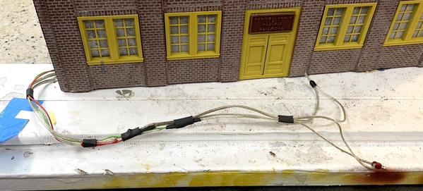
I cabled the three LED systems into a single connection. They are in parallel with the LEDs in each system in series. They're connecting to a 12VDC power source. After making the solder joints and shrink tubing them, I added shrink tube loops to tie them all together.
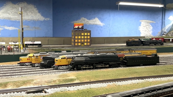
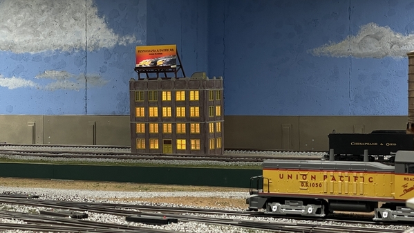
Here's the finished product on the layout.
The site is bare… very bare and needs some stuff.
The sign lighting works!
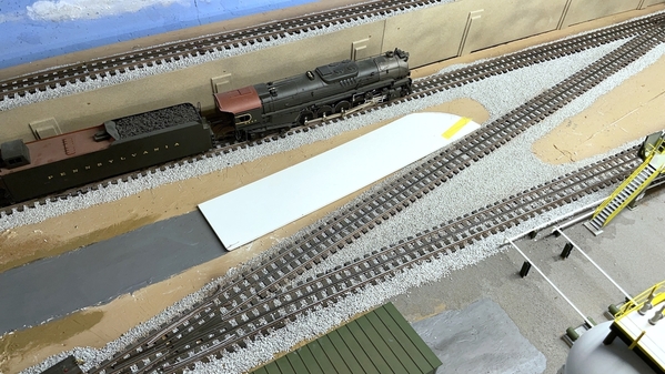
Now it needs the access road. There's a hitch here. A bunch of the work is going to take place behind the petro-chemical plant. It's very, very hard for me to get back there to do any kind of site work. I started out by building up the roadway so it matched the rail head height using many scraps of foam core. In fact, I've used just about all of the foam core and will have to get some more.
The first piece developed the right angle turn to align it with the slanted railroad. That's one of my favorite locos sitting there: a 3rd Rail Pensy J1-a. It was the second engine I purchased in 1996 when I got back into model trains.
I layered some card stock to further raise the roadway to get the rail head height. This will be slathered in some form of material or another. I've been using pre-mixed tile grout for roads with decent results.
I cut and fit the other side of the cross-over. It's a ridiculous turn, but were in magic O'gauge land so it's alright.
I tapered the other end to transition back to the original roadway. I wish I had the foresight to have built the entire road BEFORE putting in the refinery. 20/20 hindsight!!
And added an extension to the other end. This may work out if I can do all the road finishing off the layout and do a "turn-key" installation. But that may be wishful thinking. Nice view of that cooling tower...
Y'all are up to date.
Attachments
Myles, the lighting for the rooftop sign looks great! The sign is illumined more evenly than I thought it would with the two LEDs. As far as the road goes, there is always going to be hindsight. If you planned every single detail out ahead of time, you would never get to building the layout perhaps. Besides, there is always going to be reason to change plans as you go.
Of course you're correct Mark! What i need is one of those Topside Creepers, but should have bought it years ago when I could have gotten more use out of it. What I am going to do is fabricate a custom arm rest that will snuggle into the open spaces in the refinery enabling me to put my weight on the area without damaging anything. That could work and solve the temporary problem. I'll keep you informed.
As always Miles, your modeling skills are amazing. Everything looks fantastic!
John
Nice job on the building, Myles. I too like the lighting on the billboard.
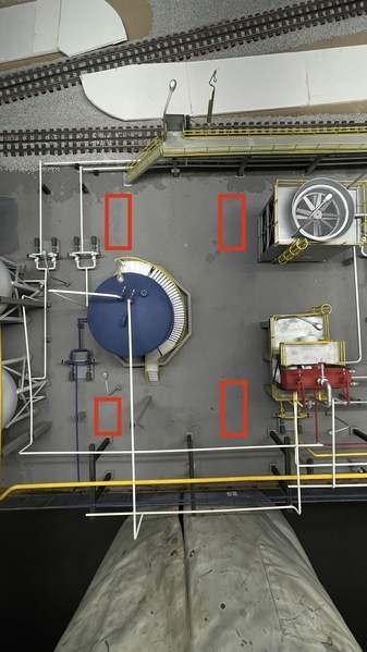
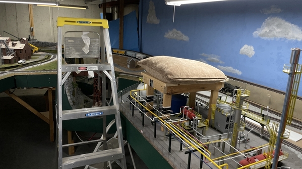
I measured the refinery and found spots that I could put a support platform without hitting anything. It will look like this. I can make it out of wood I have laying around. I'll put something soft on top to protect my delicate old arms.
Here's the space. The legs can't be all the same size! I just realized that when I added the little rectangles over this image. So I went back and changed them. The above is the corrected version. I'll make the final spacing decisions in the field.
Here's the overhead view of the spacing. Please forgive the very soiled lab coat. This support should let me lean way over the layout to do the ground cover work without wrecking the refinery in the process. At least that's the plan. It's a "poor man's Topside Creeper".
Attachments
Looks like a good plan
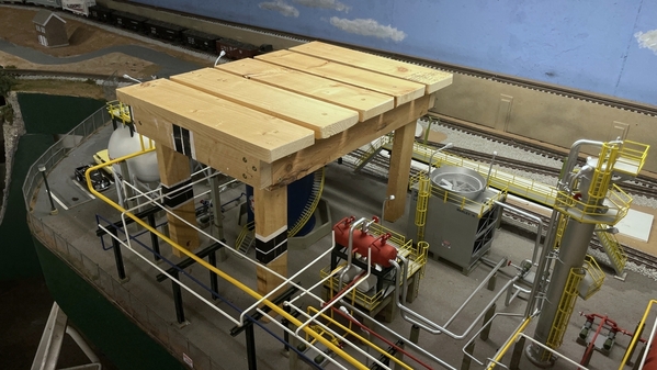
Took about an hour to cobble together the arm rest using scrap lumber I've had hanging around. In fact, when we had the new Andersen Windows installed I had to remove valences that the previous owner had installed. It took a while to remove hundreds of staples and padding, but I got a good amount of useful 1X4s.
I held each part on the refinery as I went along to ensure that it would fit without impinging on anything. I use SPAX screws exclusively when building wood stuff for the trains. They are far and away the most sophisticated design that works perfectly. They TORX drive so they don't cam out. They have a fluting on the threads that helps cut the threads into the wood. They had a thinned neck above the threaded section that the lets the upper part of the screw to pull the two pieces together. Not all Home Depots have them. I started using them more than 20 years ago in Germany when I built the first version of the RR. Since then I've found them in the USA and they're now being manufactured here as well.
I tested it with the pillow. I can get way over the refinery and will be able to work that difficult space without any interference. I can probably use in other areas as well in the back and over the town. I can disassemble it and change it's shape and size to accommodate other areas of the layout.
Attachments
I like it, Myles. It could even serve as a seat.
Just checking in. Haven't done the road work around the refinery yet (basically I'm procrastinating), but have been doing a lot on the turret project. Started to print stuff below the gun house level. The gun house is going to be screwed onto the base instead of gluing so it's removable in case something is amiss. I'm able to print many of the lower level decks and partitions and this will save asembly time, but increase painting challenges.
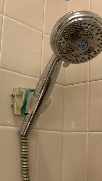
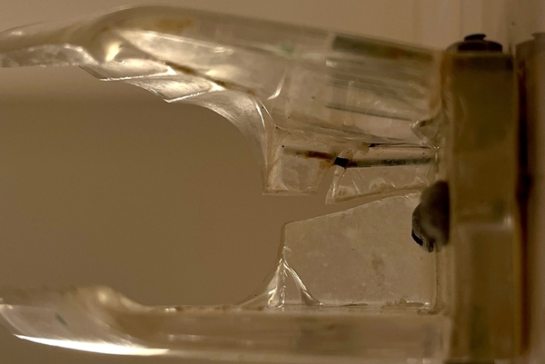
Meanwhile, on a completely different track (pun intended), I actually used my 3D printing skills to make a home repair. We have Waterpik Hand Shower that clips into a plastic bracket that's screwed through the wall tile. This was installed by the previous owner at least 13 years ago, but probably much longer than that. It fractured across the back shortly after we moved here and I repaired it with a couple of stainless steel threaded rods and nuts to pull the back together and provide integrity. Then one of the wings started fracturing and it wouldn't grip the shower head. I fixed this by drilled vertically through the back into the wings and used steel brads to reinforce it. I did that twice. Finally, as it continued to disintegrate, I resorted to large rubber bands to keep tension on the shower head.
This shows the extent of the damage.
I took pictures of it from various views and drew it on SketchUp. There were lots of compound curves so it took two tries to get it right.
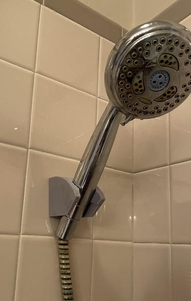
Here's the new one doing its job. It could still be better, but I have to buy a new hand piece and I highly doubt that it will have the same handle dimensions as this 15+ year-old one, so I may have to re-draw another for the new one. These kinds of brackets are no longer used with hand showers. What I see now are those that slide up and down a metal pole for various heights. Those poles would require drilling in the tile and would mean we'd have two holes with screw anchors from the original.
The resin one I believe is stronger than the original. I'm using a 85/15% mix of Elegoo ABS-Like resin and Siraya Tenacious. Tenacious is a completely flexible resin and adding to the fairly brittle Elegoo produces a much more impact resistant product. I can drop most prints on the floor and not have them shatter as they did before I found this mix.
I apologize for getting off the train topic, but I've become a 3D printing prophet and like to spread the word of just how amazingly useful this invention can be.
This past Wednesday was the day I was supposed to be visiting the USS New Jersey for my private research tour. That didn't happen. in fact, the entire East Coast trip didn't happen. My daughter and son in law came down with COVID-19 and we had been directly in their company Tuesday weekk ago. They had cold symptoms and thought that's all it was, and my daughter kept testing negative. We all wore masks and my wife and I are double-boosted. The day before we were to leave, our daugther tested positive. Meanwhile our son in law had flown to California to visit his sister. He was with them for about an hour when his brother in law suggested he test, and he was positive too! 48 hours later, his sister and her husband were positive with symptoms. That bug is contagious!!
Meanwhile, my wife and I tested negative, no symptoms and are in good health. If we were going to get it, this would have been the time.
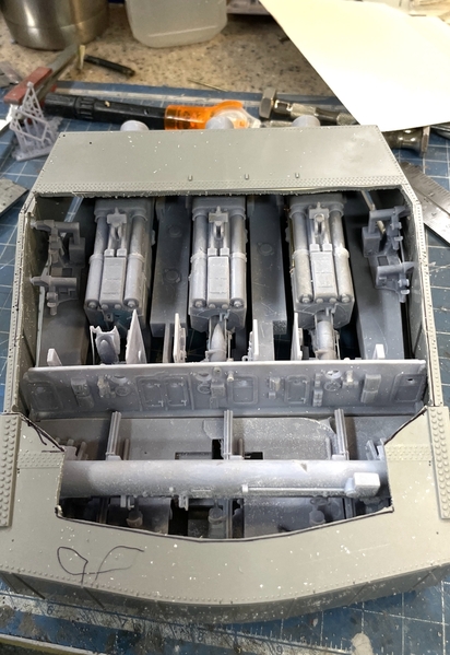
Here's a progress shot of the turret. The top's open now and I did a trial fit of some gun house stuff to see how it work. I've epoxied fitted blocks into the corners to provide some mass to accept small screws. I'm having to decide whether or not to enclose this opening with clear acrylic. Some of my blog fans say leave it open, others say close it. I've asked the curator to tell me how it's going to be displayed on board ship and how much dust protection it will get. I am going to make the partitions in the foreground out of clear acrylic so the side-gun details can be seen.
Have a nice Sunday!
Attachments
I will be interested to see how durable that bracket turns out to be in practice. I have been working on a project to reproduce Lionel Super-O track ties, and my biggest problem is finding a resin recipe that is adequately flexible and strong. Everything I try (including Tenacious) seems great until suddenly it fractures unexpectedly. It seems to get more brittle over time. Maybe I am getting the exposure wrong. Could you share the settings you are using with that particular mixture on your newer printer?
Of course, your piece is probably much more massive and solid than is possible with the track.
The bracket is very strong, but no longer needed. We bought a new hand shower that's magnetic and my wife can reach it.
I am still here and still doing things. I just finished a trip back to Philly and toured the museum Battleship New Jersey with a special private tour that answered all my questions. I won't bore you with the details, but the visit was spectacular.
And I also visited the Newtwon Hardware House and took lots of pictures of the interior including some using my new found 3D LIDAR scanner on my iPhone 12 Pro. I captured the entire counter that dates back to 1899. You can also measure directly on the scan with the phone and I now know all the critical dimensions to reproduce this piece. I scanned the long wall shelves and a neat lazy susan cabinet that, which is a reproduction of those that were in the original store. You'll notice that largish safe on the back wall. The legend goes that in 1899 burglars tried to blow that safe with dynamite and instead blew up the entire building, leaving the safe unscathed. That's why the place burned down… or so they say.
As a complete aside, my contractor brother in law told a story about a Trenton mobster who decided to commit suicide by turning on the gas in his apartment and blowing up the building with him in it. He went into the stairwell, lit a cigar and expected to be extinguished. Instead, the upper floor of the building blew up and out, injuring, but not killing him. My brother in law was contracted to remake the building one story shorter. I guess that's the definition of a loser.
In addition to making the scan, you can also export a movie of it. Here's the movies of the counter and the display cabinet. I've already drawn the display cabinet. It's all in one quick movie clip. Ignore all the background noise. I was focusing on the counter and the camera picks up background information too.
You can also export the scan via other 3D formats. I tried first to export as an STL directly into SketchUp.
And this is what you get. It's barely intelligible. This is actually the graphic structure of an STL. It's a forest of triangles. It can't print because the object is entirely open… everywhere, and is clearly not a solid.

I then imported it into Blender using a different format, and got something that looked like an object. I used the .FBX format and got this.

This at least looks like the counter. I then exported this as a STL file to SketchUp and got this. Whie it's still a mass of indistinguishable triangles, you can make out the counter and that's all I want. I know the exact measurements of the triangle since I can measure them on the 3D scan in my phone, so I can draw the correct shapes using all this mess just to establish the correct geometry and proportions.
 '
'
The long leg is 8'8" long and it's 3'3" high. With that I can do the rest. First I will erase all the background and foreground clutter to just expose the counter.

I then had to scale the entire drawing to full 1:1. As it imported, the whole thing is just a 1/16" tall. I don't know why. I opened the group and drew a line parallel to one of the edges. I measured this line with the measurement tool, clicked the mouse and then wrote in the actual height of 3' 3". It asks if you want to scale the whole group and you answer YES. Now the STL is the same size as the final parts. I then drew a rectangle on the horizontal plane that was the correct lenght of 8'8" and a width of this part of 26". I made the drawing a separate group so it could be manipulated and extracted without all the noise. I extruded the rectangle upwards to the 3' 3" height.
On the Scaniverse image I also measured the left hand leg, it's depth (different than the right leg) and pulled this rectangle out to the correct length of around 6'

When I separated the two drawings I got this.

I then started laying in all the drawers, again based on measurements from the 3D scan. That's as far as I've gotten.

So, while you can't have the luxury of simply scanning an object and having it as a printable solid in one easy step, you can work with the scanned image to get a good representation that has the correct proportions. It's no more difficult than using match Photo, but that's limited by having images with good straight lines running to two vanishing points. I believe with the $800 scanners you can make printable scans, but not with the single LIDAR on the phone.
I did the same thing with the lazy susan and here's what that looks like now. Both scans are in the movie.

I found out how the stairwell and the rest of the store interact. I also found out that the openings between the two stores is about 14 feet wide, much wider than what I had drawn.
I took panoramic images of all the aisles, and shelving (which also dates to 1899), and then took exterior pictures of all four store windows. I will see if I can use them. I still have to decide whether or not I'm going to detail the interior with photo images or actual 3D printed parts. Maybe a hybrid...
The back wall: with the famous safe...

The side wall in the original left side hardware store showing that 1899 shelving.

And the large opening between the two stores.

An example of the pano shots: I took one of these standing over each of the total six aisles. Some kind of composite of these might also work.

Armed with all of this information, I should be able to make a reasonable interior. I still have to schedule my appointment at the First Build Makery to laser cut the walls for this interesting building. I already received and paid for all the laser cut windows and acetate from Rail Scale Models. Push comes to shove, I'll pay Stephen Miley to laser cut the walls too. My problem with using him for this project is his limit to 3/16" stock. I want to cut it out of 1/4".
Re: the turret project: I got into all the places I needed to develop a complete understanding to finish the job. I also found a whole lot of things that I did wrong due to lack of information. I have a lot of reprints to do, and some new ones with the last remaining pieces. I was able to meet the curator, Ryan Szimanski and we discussed where the model will be displayed. He wants it on the main deck where ALL visitors can see it, so those with disabilities can get an idea of the turret's complexity without actually going in. My visit was so unique that our tour guide was very happy since I was getting him into spaces where he was not allowed to go.


