
Control Panel


I've been playing around with the idea of putting together a control panel for our conventional layout.  The above design is roughly 14 inches tall by 24 inches wide.  I realize I have a bit of dead space where the American flag and Lionel logo are, but wanted to keep some space for expansion.  I envision this being one of those slightly slanted panels that is attached to the side of the table.  Most of the accessories will be activated via buttons on the front side of the table.

The top row of 022c controllers are for the upper level switches and the lower row of 022c controllers are for the lower level switches.  The yellow striping is the upper level track plan and blue is the lower level.  The gray circles in the track are on/off toggle switches  The two black 5132 switch controllers (w/o lights) will be used to control a lionel 497 coaling station.  The red button is for a whistle station.  The black circles below the voltmeters are in-line magnetic circuit breakers.

My questions:

1.  What are your thoughts on the overall layout of controls?  Is 14x24 too big/awkward to use? Should the voltmeters and ammeters be flipped?

2. How do people label the turnout locations so that you can easily tell which switch to throw?  Do you add little numbered flags near the actual switch? Add numbers to the track diagram?

3. In terms of wiring the circuit breaker, voltmeter, and ammeters, should the breakers be closest in series to the transformer or the track?

4.  The 12 switches with incandescent bulbs are starting to really eat up some wattage.  What is the best source for drop-in red and green led bulbs that have the same size bulb and coloring as the incandescents?

5. I was thinking about using 1x4" pine as the frame and 1/8 inch plywood for the surface.  Would this strong enough after I cut the holes in the surface for the meters?

6. Any tips on the material, construction, design, and/or process would be appreciated!


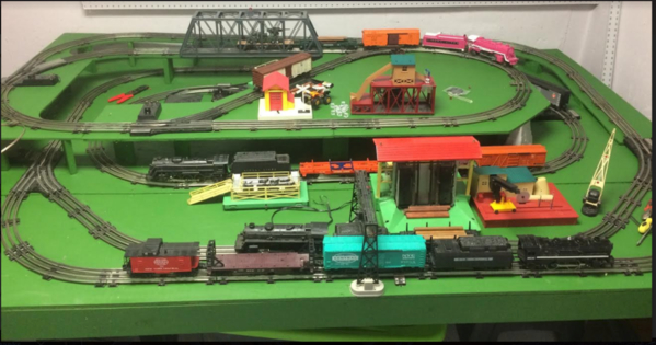
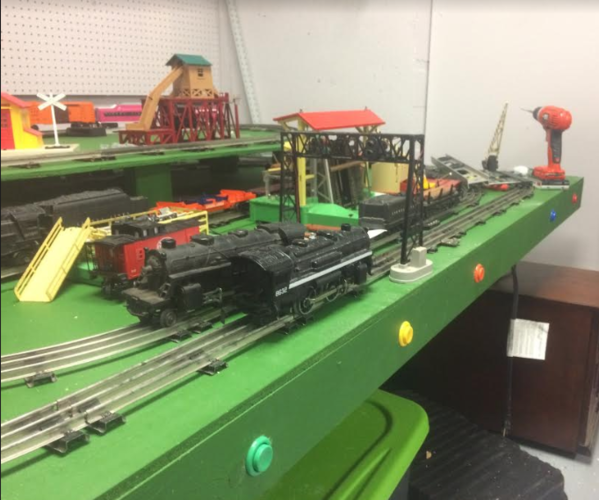
Thanks!  Here are a couple old pics of the layout before I added some sidings seen in the control panel track diagram.


Attachments

Images (2)
  • Control Panel
  • mceclip0
Last edited by JD2035RR
Original Post

Replies sorted oldest to newest

How close to actual scale is your cut and paste of the different pieces?

I note you don't show cables leaving the controllers at all.  The switch controllers, especially, being placed so close together and right up to the edge.

Are you intending to hinge this so you can access the underside for maintenance?

This may just be my personal preference, but I'd probably put the meters (and circuit breakers, I guess) above the transformer, not below it.  This could also help with wires being too close to the edges (meters are likely with terminals near the middle, the ZW obviously has it's outputs on the edge, which is right up against the upper edge of the panel in the above pic.  (inter-related with question on hinge desire).

-Dave

If this will be attached to the side of the layout, it will have to be very structurally robust to hold the ZW.  Often panels like this are located near or next to the ZW which is separately mounted.  Moving the ZW would allow for a larger layout drawing.  Any momentary contact push button switches will operate the switches.  You can get push buttons and then mount them on the layout drawing exactly on the switched track.  Could do lights too.  This eliminates the need to number or label the switches.  Often in a conventional layout there are several electrical blocks.  Toggle switches can be mounted right o the diagram for turning the blocks on and off.

Do a forum search.  Lots of threads about control panels, including one a couple of months ago.

JD,

I think we discussed this in another thread but check out thread linked below on Lionel Dealer Display Layouts. It's many pages but has some good pictures of layouts with PW-style control panels.

Granted most of them don't have the number of items you are planning on (although most have ZWs) but may give you some ideas, especially on attaching to the layout board. 

https://ogrforum.ogaugerr.com/...-and-postwar-layouts


Just to give you an idea my control panel is 15"X24". I don't have any switch controllers (I use Ross switches with ground throws) but have 3 UCS track controllers, several accessory controllers, block toggle controls, and a ZW and Type Z transformers in basically the same space you're looking at constructing. I did build a shelf below the control panel to hold a TIU and TMCC Command Base. 


20190226_201340

Attachments

Images (1)
  • 20190226_201340

It would appear that you have a Volt/Amp meter pair per ZW channel.  What does each channel control?  On your layout you show multiple engines on the track.  Do you use Blocking to control the engines individually?  Therefore not being sure of the afore mentioned questions, you may wish to add some spdt center off switches to control your blocks.  Just my 2 cents and it may be all it is worth.

Dave45681 posted:

How close to actual scale is your cut and paste of the different pieces?

I note you don't show cables leaving the controllers at all.  The switch controllers, especially, being placed so close together and right up to the edge.

Are you intending to hinge this so you can access the underside for maintenance?

This may just be my personal preference, but I'd probably put the meters (and circuit breakers, I guess) above the transformer, not below it.  This could also help with wires being too close to the edges (meters are likely with terminals near the middle, the ZW obviously has it's outputs on the edge, which is right up against the upper edge of the panel in the above pic.  (inter-related with question on hinge desire).

-Dave

Thanks Dave. Scale is pretty close. I used excel as a background grid as graph paper of sorts.  Good point on leaving extra room for the wiring to exit the controllers and bend down into holes. I definitely need more spacing between them. 

Hinging it is another good idea. I would surely need to have the ZW anchored separately from the panel. I’ll have to play around with that. 

ogaugenut posted:

If this will be attached to the side of the layout, it will have to be very structurally robust to hold the ZW.  Often panels like this are located near or next to the ZW which is separately mounted.  Moving the ZW would allow for a larger layout drawing.  Any momentary contact push button switches will operate the switches.  You can get push buttons and then mount them on the layout drawing exactly on the switched track.  Could do lights too.  This eliminates the need to number or label the switches.  Often in a conventional layout there are several electrical blocks.  Toggle switches can be mounted right o the diagram for turning the blocks on and off.

Do a forum search.  Lots of threads about control panels, including one a couple of months ago.

I think mounting the ZW separately to the side might be the way to go, for stability and possibly hinging the rest of the panel. The momentary switches in the diagram are probably the most logical way to go, but I like those darn 022c controllers too much. They’re too big, eat up too much wattage, are difficult to clearly assign to the turnouts, but I like them too much to get rid of them...maybe I could add the diagram switches and tie them into the 022 wiring. 

I have seen a lot of panels on the forum, they are really cool. Thanks for chiming in. 

johnstrains posted:

JD,

I think we discussed this in another thread but check out thread linked below on Lionel Dealer Display Layouts. It's many pages but has some good pictures of layouts with PW-style control panels.

Granted most of them don't have the number of items you are planning on (although most have ZWs) but may give you some ideas, especially on attaching to the layout board. 

https://ogrforum.ogaugerr.com/...-and-postwar-layouts


I really enjoy that thread. The dealer display slanted panel is what I’m going for, although most are quite short, less than 10 inches or so. Also, a lot of those dealer displays had the controls mounted right on the table top. 

AAB81A87-2EB8-4FDE-896C-1A802213EB86

Attachments

Images (1)
  • AAB81A87-2EB8-4FDE-896C-1A802213EB86
Lou1985 posted:

Just to give you an idea my control panel is 15"X24". I don't have any switch controllers (I use Ross switches with ground throws) but have 3 UCS track controllers, several accessory controllers, block toggle controls, and a ZW and Type Z transformers in basically the same space you're looking at constructing. I did build a shelf below the control panel to hold a TIU and TMCC Command Base. 


20190226_201340

Thanks Lou. Seeing the same space in reality helps bring it into perspective. I didn’t realize those Zs were so big! 

Loose-Caboose posted:

It would appear that you have a Volt/Amp meter pair per ZW channel.  What does each channel control?  On your layout you show multiple engines on the track.  Do you use Blocking to control the engines individually?  Therefore not being sure of the afore mentioned questions, you may wish to add some spdt center off switches to control your blocks.  Just my 2 cents and it may be all it is worth.

Thanks Jim. I do have a relatively simple blocking system set up. The upper level (yellow on the diagram) is controlled with the left handle. The lower level is controlled by the right handle (blue on the diagram). Between the upper and lower loops are passing sidings that are independently blocked (on/off) both of which are powered by the right handle. I plan to block the sidings on the upper level to park an engine or two. 

One inner dial is for switches and the other is for accessories. 

JD2035RR posted:
johnstrains posted:

JD,

I think we discussed this in another thread but check out thread linked below on Lionel Dealer Display Layouts. It's many pages but has some good pictures of layouts with PW-style control panels.

Granted most of them don't have the number of items you are planning on (although most have ZWs) but may give you some ideas, especially on attaching to the layout board. 

https://ogrforum.ogaugerr.com/...-and-postwar-layouts


I really enjoy that thread. The dealer display slanted panel is what I’m going for, although most are quite short, less than 10 inches or so. Also, a lot of those dealer displays had the controls mounted right on the table top. 

AAB81A87-2EB8-4FDE-896C-1A802213EB86

Agreed,  you would probably want something longer.

I think those Lionel panels were attached with a carriage bolt arrangement. I've seen a good how-to on these somewhere. Could have been here on the forum? Also, I think CTT Magazine did a series on building a PW display that used these attached panels.

Only thing I can add is that I use white pegboard for the base. It is not that pretty but the holes are there ready to use.

With respect to turnout identification I make small signs with numbers on them. The top printing designates siding, mainline, yard etc but the numbers are unique and not repeated.

Turnout ID 004

Dirty Dog Railway 0017

Attachments

Images (2)
  • Turnout ID 004
  • Dirty Dog Railway 0017
Joe Fauty posted:

Only thing I can add is that I use white pegboard for the base. It is not that pretty but the holes are there ready to use.

With respect to turnout identification I make small signs with numbers on them. The top printing designates siding, mainline, yard etc but the numbers are unique and not repeated.

Turnout ID 004

Dirty Dog Railway 0017

Nice signs - I like that they look part of the scene. I like the pegboard, but really like the drawer slides 👍

About a Control Panel ...
My L-shaped O-gauge layout is placed in an L-shaped room, which is an addition to the rear of the house. Aisle space around the perimeter is limited, so I didn't have room for a slant-mounted control panel which would consume most of the aisle space.  Instead, I installed two pull-out sliding shelves placed near the angle of the "L."  See attached pix.

One slide-out panel is for some control buttons and all the O22 switch controllers -- like you, I prefer the iconic look and feel of them. Each switch controller is numbered, and there are corresponding "ID flags" at each switch (some of which are semi-hidden from view from the control panel). With an apology to Old McDonald's Farm, I used yellow flex-plastic livestock ear tags as the "flags." They are big enough to be seen from nearly 20 feet away.

The other pull-out shelf holds Lionel and MTH "bricks" -- a PM-1 for track power and TMCC gear, and two MTH Z1000 "bricks" for accessories, building lighting, and switches. The 110v power to everything on the layout comes from three different wall outlets with power cords going to power strips mounted on the undersides of the five layout platforms. Each outlet has a remote control gizmo with a hand-held controller device - bought from a local "Big Box" store.  When I push its three buttons, the AC power to all three circuits is turned on/off. In effect, the gizmo is a Master Power Switch.

Like many  other hobbyists, I mounted the pushbutton controls for the operating accessories on the perimeter fascia board of the layout; each button is mounted near its accessory. I use Lionel #90 control buttons for that purpose if possible.

I used a different method for track power to the upper level; I installed a PC power supply (90 watts) for DC voltage as track power for three short trolley lines. That DC power is routed through three voltage controllers mounted in a small black box with a small knob for each; handy for individual speed control of each trolley. I installed four 110v power strips underneath the upper platform - which provides power plug-ins for 36 DEPT 56 porcelain lighted buildings from their NORTH POLE VILLAGE collection. I used the voltage reduction strips made by Dept 56 to provide 3v to the lamps in most buildings to avoid running 110v wires everywhere. So far, so good; no overload problems.

The advice offered by other OGR FORUM members makes practical sense. One final comment ... consistently apply a color code to all wiring, dress-up the wires neatly to avoid the look of "an explosion in a spaghetti factory, and (like meticulous computer or military electricians) attach wiring numbers to each wire for identification later.

Carry on ...

Mike Mottler     LCCA 12394
mottlerm@gmail.com


Attachments

Images (4)
  • Switch Controller Panel
  • Switch Tags
  • Switch Tags in Place
  • Mike Installing a Switch ID Tag

IMG_3790

Uncouple and UCS Tracks Upper Left.   My switch controllers are laid out in the order the switches are in my Layout.  The Atlas Twin is used to control exit signals from my yard lead.   The Connector with the yellow switches are on/off for track power at the end of my yard tracks.  The Atlas Connectors with the green switches are block control for both yard tracks and mainline tracks. 

Steve

Attachments

Images (1)
  • IMG_3790
Mike H Mottler posted:

About a Control Panel ...
My L-shaped O-gauge layout is placed in an L-shaped room, which is an addition to the rear of the house. Aisle space around the perimeter is limited, so I didn't have room for a slant-mounted control panel which would consume most of the aisle space.  Instead, I installed two pull-out sliding shelves placed near the angle of the "L."  See attached pix.

One slide-out panel is for some control buttons and all the O22 switch controllers -- like you, I prefer the iconic look and feel of them. Each switch controller is numbered, and there are corresponding "ID flags" at each switch (some of which are semi-hidden from view from the control panel). With an apology to Old McDonald's Farm, I used yellow flex-plastic livestock ear tags as the "flags." They are big enough to be seen from nearly 20 feet away.

The other pull-out shelf holds Lionel and MTH "bricks" -- a PM-1 for track power and TMCC gear, and two MTH Z1000 "bricks" for accessories, building lighting, and switches. The 110v power to everything on the layout comes from three different wall outlets with power cords going to power strips mounted on the undersides of the five layout platforms. Each outlet has a remote control gizmo with a hand-held controller device - bought from a local "Big Box" store.  When I push its three buttons, the AC power to all three circuits is turned on/off. In effect, the gizmo is a Master Power Switch.

Like many  other hobbyists, I mounted the pushbutton controls for the operating accessories on the perimeter fascia board of the layout; each button is mounted near its accessory. I use Lionel #90 control buttons for that purpose if possible.

I used a different method for track power to the upper level; I installed a PC power supply (90 watts) for DC voltage as track power for three short trolley lines. That DC power is routed through three voltage controllers mounted in a small black box with a small knob for each; handy for individual speed control of each trolley. I installed four 110v power strips underneath the upper platform - which provides power plug-ins for 36 DEPT 56 porcelain lighted buildings from their NORTH POLE VILLAGE collection. I used the voltage reduction strips made by Dept 56 to provide 3v to the lamps in most buildings to avoid running 110v wires everywhere. So far, so good; no overload problems.

The advice offered by other OGR FORUM members makes practical sense. One final comment ... consistently apply a color code to all wiring, dress-up the wires neatly to avoid the look of "an explosion in a spaghetti factory, and (like meticulous computer or military electricians) attach wiring numbers to each wire for identification later.

Carry on ...

Mike Mottler     LCCA 12394
mottlerm@gmail.com


Great insight, Mike! I like the livestock tags. Good advice on the wiring, it can easily slip into the ratnest category if you’re not diligent. 

Steve24944 posted:

IMG_3790

Uncouple and UCS Tracks Upper Left.   My switch controllers are laid out in the order the switches are in my Layout.  The Atlas Twin is used to control exit signals from my yard lead.   The Connector with the yellow switches are on/off for track power at the end of my yard tracks.  The Atlas Connectors with the green switches are block control for both yard tracks and mainline tracks. 

Steve

Nice work, Steve. Is your panel on a separate table/cart?

JD2035RR posted:
Steve24944 posted:

IMG_3790

Uncouple and UCS Tracks Upper Left.   My switch controllers are laid out in the order the switches are in my Layout.  The Atlas Twin is used to control exit signals from my yard lead.   The Connector with the yellow switches are on/off for track power at the end of my yard tracks.  The Atlas Connectors with the green switches are block control for both yard tracks and mainline tracks. 

Steve

Nice work, Steve. Is your panel on a separate table/cart?

Yes  Basically a plywood box on casters.   Here is the back.

IMG_3793

Steve

Attachments

Images (1)
  • IMG_3793

Add Reply

Post

OGR Publishing, Inc., 1310 Eastside Centre Ct, Suite 6, Mountain Home, AR 72653
800-980-OGRR (6477)
www.ogaugerr.com

×
×
×
×
Link copied to your clipboard.
×
×