
Good Afternoon,

     I purchase several of these impressively cheap Signal lights.  They do however like so many LED's use a 3-12v DC power supply which I already have running under the table.  My question is how to wire in some relays to activate these from segmented *isolated* track, I am looking for a rather cheap option as items such as ross DZ-1008A run about $18 each.  https://www.ebay.com/itm/1-lot...9:g:Y6EAAOSwRqldy8Sd.

I have a ZW-L power supply on Ross Track


Thanks,

Alex


Last edited by TACOROG
Original Post

Replies sorted oldest to newest

Alex: You are new to the forum and may not have seen the relay modules that are much less expensive. Since you're no stranger to eBay, try the following number in the search box:

183776948137

Make these your starting point. The relays are rated for 10 amps; perfect for running O-gauge model trains. They will certainly work to fuel your crossing signals.

They do take a bit longer to arrive since they come from overseas. But you can find US sellers on eBay as well with the price a little higher.

Attachments

Images (1)
  • mceclip0

Segmented?  As in isolated rail triggers?.A relay's coil and it's points seldom share terminals.  So you wire the points side like a switch (that has a motor 😜)

"how to" depends on some more variables and with the info listed, seems almost vague...like you already know how but want to doublecheck...but managed to leave something out...I just don't see where you.are.stumped.

Now the motor half is just two wires, one goes to the inside rail, the other goes to the isolated rail. Wheels then complete the circuit giving the isolated rail a connection to the outer rail via the wheels/axles

Relays have two value sets listed; You want a relay that uses low amps @ the track/constant voltage or varible( e.g. 0.25a @ 3v-12v means the relay triggers with as little as 3v thru 12v max(I'd look for one handling a 24vac max.

The point count, action type, and strength(amp/volt max) should handle the max load you use. They follow the labeling style of a a switch and may be momentary, latching, etc, or have multi poles or throws etc. (spst, spdt,etc)

If the 3-12V DC supply which you "already have running under the table" comes from a wall-wart, then you don't need a relay to use the insulated-rail method.

ogr crossing dc

That is, if the DC supply is indeed isolated (i.e., comes from a separate transformer as a wall-wart would) from your ZW AC track voltage, then you can tie the DC and AC grounds together.  Your crossing signal's DC+ would connect to the DC+ supply and the crossing signal's DC- would come from the insulated track section when occupied.

Attachments

Images (1)
  • ogr crossing dc
Last edited by stan2004

Stan: Something I've puzzled over is why a wall-wart is okay to use in this situation as opposed to other methods that convert AC to DC; like the bridge rectifier on the AC/DC buck converters. I understand that the bridge rectifier creates a separate ground that differs from the transformer ground.

But what does a wall-wart do to make their DC ground compatible? I'm guessing that they use a single diode to produce half wave DC as you have pointed out previously. Then they are simply passing the AC ground through which makes it common with the AC ground from the transformer.

And what about DC from an old computer power supply? Is that not compatible? And how is it that you know this stuff?

You may want to look into optocouplers/optoisolators. 

All you need is a bi-directional optocoupler. I used LTV-844 optocouplers which have 4 channels per chip. It is called an optocoupler because the two leads that connect to the sensing side (insulated rail setup) illuminate a small LED. The illumination of that LED then closes a separate circuit comprised of a photosensor. Below is the break out of the LTV-844:


Image result for LTV 844


Pin 1 would go to the insulated rail, pin 2 to a fixed AC voltage source (or center rail) through a current limiting resistor. When pins 1 and 2 make up a closed circuit via metal axles, the LED is illuminated (for the astute, you will see that this selected optocoupler has two leds in reverse polarity so that they will work off of the AC voltage of the track). The light from the LEDs active the photosensor between pins 16 and 15, closing a digital circuit that can be connected to the low voltage logic of Chinese relay boards. When the block is occupied, pin 15 will read a digital 1 at VCC, and when not occupied, a digital 0 (again, pull down resistor recommended).

This also enables complete isolation of the AC track and the DC accessories so there is no concerns if you derive your DC from an isolated or unisolated transformer/power source.

Last edited by bmoran4
Consolidated Leo posted:

Stan: Something I've puzzled over is why a wall-wart is okay to use in this situation as opposed to other methods that convert AC to DC; like the bridge rectifier on the AC/DC buck converters. I understand that the bridge rectifier creates a separate ground that differs from the transformer ground.

Exactly!  It's just that when using a bridge rectifier in the AC/DC buck converters the new/separate DC ground output was derived from the AC ground input and hence has a blood-line relationship.  You cannot then marry the two ground signals as that would be electrically incestuous.   Not trying to be clever with the geneaology metaphor; it's just that I've previously tried to explain the technically precise requirement of galvanic isolation but doesn't seem to get the point across.  

But what does a wall-wart do to make their DC ground compatible? I'm guessing that they use a single diode to produce half wave DC as you have pointed out previously. Then they are simply passing the AC ground through which makes it common with the AC ground from the transformer.

A wall-wart has an internal transformer which means its AC output has no blood-line relationship to the train transformer's AC output.  So now, even if the wall-wart internally spawns a DC ground using a bridge rectifier, the wall wart's DC ground output still has no blood-line relationship to the AC ground of the train transformer.  Hence the two signals can tie the knot and live happily thereafter.  Note that you cannot access the internal AC ground of a wall-wart.

And what about DC from an old computer power supply? Is that not compatible? And how is it that you know this stuff?

A computer power supply has an internal transformer so it is like a wall-wart.


bmoran4 posted:

You may want to look into optocouplers/optoisolators. 

...

Indeed.  It's just that every time I look on eBay I can only find pre-assembled modules for DC-to-DC applications (rather than AC to DC).  Maybe one of the guys messing around with DIY circuit board design could be coaxed into designing such a module.  I really like the no-soldering, screw-terminal convenience.  And the eBay/Asia price is less than you'd pay for shipping from DigiKey! 

4 channel dc optocoupler

Attachments

Images (1)
  • 4 channel dc optocoupler

Well, the module claims amps, but I find that around 300-350ma is about the limit, that's likely partially due to the size of my input filter caps.  I have actually laid out another board with 680uf of capacitance instead of 300uf to increase the potential current output, but I haven't actually needed the additional capability yet.

Truthfully, I make these as small as possible as I am usually trying to cram them into something with wheels.   For accessories, I'd buy one of the larger buck DC-DC modules and just tailor an add-on PCB with the AC/DC components.  For higher currents, you'll likely want even more bulk capacitance, so there's no reason to limit the size based on this particular design.

Attachments

Images (1)
  • mceclip0

Well of course! Galvanic Isolation! Why didn't I think of that? I must have used that term NEVER in my programming career!

Anyway, Stan, I think I understand the concept at a basic level. The AC from the internal transformers (through inductance) create an independent source that can be run through a bridge rectifier without causing any problems when mixing AC and DC through the same conductor. That's a good thing to know. Thanks!

stan2004 posted:

Indeed.  It's just that every time I look on eBay I can only find pre-assembled modules for DC-to-DC applications (rather than AC to DC).  Maybe one of the guys messing around with DIY circuit board design could be coaxed into designing such a module.  I really like the no-soldering, screw-terminal convenience.  And the eBay/Asia price is less than you'd pay for shipping from DigiKey! 

To preserve the forks in the family trees, I've saved a picture of the module. If I can figure out what all they have on their PCB, I'll try to duplicate it for another one that accepts AC or DC inputs. Beating their prices might be a bit difficult though!

Last edited by rtr12

Stan, thinking I would try to duplicate the board shown above... I'm stuck trying to trace out the wiring of the example board above. Found a better picture here. It has a magnified view for close ups and appears to be the same board.

The problem is in following the board's traces to the components? The pinouts of the LTV-8141 and PC817 appear to be the same from their data sheets. So here's what it looks like to me so far, but it also doesn't look to be correct either? I think the whole thing is in need of a few corrections. My PCB tracing is about on the same level as my circuit designs, both still needing a lot more work!

AC-DC 4 Opto-Iso PCB-1 SM


Attachments

Images (1)
  • AC-DC 4 Opto-Iso PCB-1 SM

Your schematic looks correct.  But if thinking of a new PCB, best to confirm there is any interest from anyone who might actually build it!  As I see it, the application is for those guys that want to use AC Accessory Voltage from an existing train transformer to fire relays triggered by insulated-rail sections.  In other words it would be inconvenient or impractical to add a wall-powered DC-output power supply.  I just don't know how many guys are in this situation.  That is, low-voltage DC power supplies for driving accessories can be had for pennies per Watt as documented in dozens of OGR threads.  OTOH low-voltage AC power for driving accessories runs about 50 cents to $1 per Watt...and for virtually all train transformers any Accessory AC power takes away available motive power to drive trains.

In any case, sticking with DC power derived from an existing Accessory AC, I'm imagining something like this:

insulated rail trigger with separate ac dc grounds

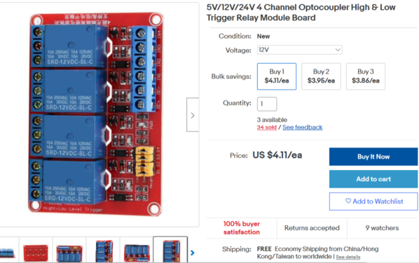
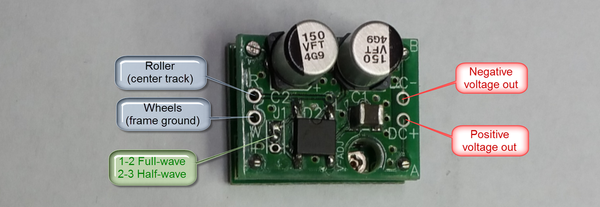
So in words, ACCessory voltage (e.g., 14-16V AC) would power an AC-to-DC power regulator module (~$3 on eBay, free shipping from Asia).  The regulator would be set to 12V DC output.  The 12V DC would power a multi-channel (1, 2, 4, 8, etc.) relay module (~$1/relay, free shipping from Asia).  The "mythical" optoisolator/optocoupler module would allow the AC insulated-rail sections (i.e., AC ground on the outer rail) to trigger the DC relays.

Let's just say this is the matter at hand.

I agree that a $2 all-in cost target is a pipe dream.  To that end, for the determined DIY'er perhaps the closest exit is to simply buy the $2 DC-to-DC optocoupler module on eBay and extract the DC-input PC817 optocouplers.  Then insert AC-input optocouplers as the pinout of the two types are the same.  The PS2505-1 is ~25 cents a piece on eBay (free shipping from Asia).

ps2505 ac optocoupler

If someone is considering doing this, I'd suggest adding a capacitor across the output to demote relay chatter from intermittent axle contact.  Also, depending on what DC output you're driving note that the AC-input optocoupler actually generates a pulsed-DC output or what amounts to 120 pulses per second which can bother some circuits - a capacitor smooths the ripple.

OTOH, if someone wants to undertake a new PCB design using DipTrace or whatever. 

1) I'd place the 4 optocouplers in a DIP-16 footprint.  You should be able to "stack" four DIP-4 packages into a DIP-16 footprint.  This way you can install a 4-channel DIP-16 component...or 4 separate 1-channel DIP-4 components using the same board.  Heck, you could even mix and match so 2 channels are DC input and 2 channels are AC input.

2) I'd lose that 2-pin programming jumper that ties the input ground to the output ground on each channel...and use the space to provision for a capacitor to demote relay chatter or buzzing.

But to repeat, I'd be curious to hear real-world applications!  I do recall a recent thread about someone trying to implement a fault detector for 4 AC brick power supplies.  That is, if any of the bricks tripped its internal breaker, then this was to trigger a global action like killing power to all tracks.  As I recall, my suggestion was to use a 4-channel AC optocoupler to monitor each AC brick voltage.  The optocoupler outputs would be wired into the logical "AND" configuration so if any input dropped out, a DC relay with high power contacts would also open and kill power.  But this was a one-off and presumably simpler to solder the handful of components rather than fabricate a custom PCB.


Attachments

Images (2)
  • ps2505 ac optocoupler
  • insulated rail trigger with separate ac dc grounds
Last edited by stan2004

Thanks for the assistance. I like the added capacitor idea and removing that jumper. I didn't realize a cap was needed? But that jumper was sure throwing me a curve. One of the reasons I thought my tracing of the example was not correct. 

Probably should have asked this before, but I have a couple more questions about the circuit.  1. - What would one be programming with that jumper?  2. - Does the 3k resistor have something to do with the programming, and is it (or any other value resistor) really needed in the output section? I didn't understand the purpose of the resistor either?

I started out with the LTV-8141. I wasn't aware of the PS2505s? They look to be similar and have the same pinouts. I had also given some thought to the 8441 (or now 4 PS2505-1s or PS2505-4) so I'll change that and try to use the 16-DIP size. I suppose one could then use the same PCB for a 1, 2, 3, or 4 input/output version. 

Earlier I was thinking about 1, 2 and 4 in/out versions on separate PCBs. Reason being, I did some fiddling with a through-hole PCB for the 4 in/out version and thought it may have been a bit large for OSHPark. Prices go up quick after a certain size of somewhere around 1 square inch, maybe a bit more. My thinking was the 1 or 2 I/O versions might be small enough for more economical pricing from OSHP. But, I haven't actually priced anything, just guessing so far. 

For the final PCB(s) my thoughts were to make a post about it and add it to the 'Projects' list. It would be just another option for anyone that has an interest. Hopefully there would be some interest? Now I'm thinking I should probably get a sample of the boards made first, just to be sure they work properly before someone else (if anyone) tries them out. Wouldn't want them to get something that didn't work. 

I also like the idea for the power shut down function. This might also be appealing to some folks here. Might be in for trying that one myself. Regardless of project interest, I do enjoy all this, always learn something along the way, get a new circuit design and have something new to fiddle with after samples are assembled. As an added bonus, if they don't work the first time, I get to try it a second time.   


If you want the 4-channel model, you can get ten of them for $4.80 shipped from AliExpress.

You can probably get away with a smaller cap on the output if you want to make it a bit smaller.  I use a 10uf tantalum cap on the Super-Chuffer for the filtering, it works just fine.  Of course, I was going for size, so I wanted the smallest cap that would do the job at 60hz.  Also, the smoke power and TMCC headlight is coming in half-wave format, so I'd need much more capacitance than you would with full-wave power.

Attachments

Images (1)
  • mceclip0

I think I'll get a few of those 4 channel chips. They might be nice to have around and are a bit more expensive here at the US suppliers. I was unsure of the cap size too, so it's good to know about that. I will go with a smaller one. I am also unsure about the 3k resistor in the output? The original DC to DC board has one. I asked Stan above, but he hasn't been back by yet.

The PCBs are still a bit pricey at OSHPark too. I cobbled together a single channel through-hole version and it was a bit over $4 for 3 PCBs. Might be able to shrink it up a little more? I might try a 4 channel SMT version to see how much that would be?

As Stan said earlier, it sure looks like buying the ready made board for $2 and swapping chips is going to be a lot less costly than making one from scratch. Of course it won't be nearly as much fun doing it that way. 

Yes, I certainly agree on just the terminal blocks being more than their complete board. They must get a 'good deal' on terminal blocks (and PCBs) over there! I have a saved ebay search for those things, which seldom shows any 'good deals'. 

The $4 PCBs were only for a 1 channel, through-hole version. 4 channel version was over $11 for the 3 PCBs. Personally, I don't mind the costs, as I enjoy fiddling with all this stuff. As an added bonus, the more I do, the more I learn. Or at minimum, learn what not to do anyway. There's 'educational' benefits either way!

Still true about adding the cap the re-work project would still be missing. Plus, also as you say, the swapping can sure be less convenient (especially when it's me doing the swapping). 

OK, here's my version 2.0 idea. Buy the eBay $2 opto-isolator module.  But rather than tediously replacing the DC opto-isolator chips with AC ones simply put a 10-cent bridge-rectifier on the screw-terminal inputs of the module.  No soldering required!

bridge rectifier for a dime

You'd still want to put a capacitor on the DC output side to smooth out the 120 Hz pulsed DC so that the relay module doesn't chatter or buzz.  As GRJ suggests, something like 10uF or so ought to do it.


Attachments

Images (1)
  • bridge rectifier for a dime

And here's version 3.0 which is even cheaper albeit only for a DIY enthusiast.  To be clear, I'm addressing the issue of insulated-rail triggering where the outer-rail AC ground cannot be connected to the relay's DC ground.  In other words, as discussed earlier, this would be where the DC power is derived from the train transformer's AC voltage using a AC-to-DC voltage regulator module that uses a bridge rectifier.

diy opto isolation using bulb and photocell

The idea is to roll you own opto-isolator with parts you may already have.  As shown above an O-gauge incandescent bulb is powered by Accessory AC and the insulated-rail section.  So the bulb turns on with Accessory AC when the train rolls over the insulated section.

Then, a 5-cent photocell (aka photoresistor, CdS sensor) is aimed at the bulb.  So when the bulb goes on, the photocell's resistance drops and this triggers the $1 DC relay module.  There are thousands of listings on eBay for photocells and might be something like:

cds photocell for a nickel

I just used one I had in the junk box so I'm not claiming the above particular component is exactly what you'd use.

And here it is in action.

For demonstration purposes the insulated-rail section is the several inches in the middle taped off with blue painter's tape.  In the first section of the video note how the left bulb flickers due to intermittent contact from dirty wheel, track gunk, etc.  The right bulb which is hooked to the DC relay output also flickers.

In the latter section of the video I added a 10 uF capacitor across the relay module trigger input.  Now notice how while the left bulb still flickers, the relay does not chatter and the right bulb is more stable.  Actually, there are 2 things working in favor of the bulb-photocell method.  First, an incandescent bulb does not turn instantly on-off like an LED does.  When voltage is removed, the filament cools down but the light decays.  Second, the "physics" of these Cadmium Sulfide (CdS) photocells is somewhat slow acting.  That is, the resistance of the photocell is somewhat slow to respond to changes in light with response times in the milliseconds.  This also helps to suppress flickering or chattering.  But a 5-cent capacitor also helps!

Obviously you'd want to build a light tunnel, such a black heat shrink tubing such that the photocell is only looking at the bulb. 

So now it might look something like this with the optical isolation costing maybe 25 cents per channel.

bulb photocell for optoisolation


Attachments

Images (3)
  • diy opto isolation using bulb and photocell
  • cds photocell for a nickel
  • bulb photocell for optoisolation
Last edited by stan2004

Your Version 2 would certainly be much more cost effective (and much easier)! So that's probably a better choice for anyone that is interested. I have used your idea of adding bridge rectifiers to DC-DC converters using 2 terminals from a small Euro style terminal strip. That works out very well (also easy to do). Maybe the same could be done with the added capacitor, if the 3k resistor doesn't interfere? I think the no soldering part is a fairly popular option around here as well. 

I have a couple of the DC-DC converters (modified for AC/DC inputs) in regular use on the work bench. One even has the inexpensive, add-on digital meter for it's DC output (other one came with a digital meter).

Edit: And I see version 3 magically appeared while I was writing this! 

Last edited by rtr12
rtr12 posted:

...

I also like the idea for the power shut down function. This might also be appealing to some folks here. Might be in for trying that one myself. Regardless of project interest, I do enjoy all this, always learn something along the way, get a new circuit design and have something new to fiddle with after samples are assembled.

...


I found the OGR thread about the power shutdown.

4%20block%20safety%20relay

To summarize, the requirement was to kill power to all 4 track blocks if the breaker trips on any of the 4 AC bricks.  So the 4-channel opto-isolator IC chip is configured as shown with the outputs "stacked" in series.  A single capacitor smooths out any 120 Hz pulsed DC ripple.

In this case that pesky 3K resistor in each channel of the eBay module is not needed though I'm guessing it would still work.  Again, it would probably be expedient to simply add a 10-cent bridge rectifier on each AC input rather than extracting/replacing the DC opto-isolator chips with AC chips.


Attachments

Images (1)
  • 4%20block%20safety%20relay

That's the shut down circuit I was sort of thinking about. I'm thinking I saved that picture from the thread too.

Some of the 4-channel opto-isolator chips from AliExpress that GRJ pictured above are on order, parts are on the way. I already have some of the relays. Now thinking about ordering one of the $2 opto-isolator boards to experiment with.

Well, I wasn't going to order any PCBs for this, but that could change. The 3k resistor could be eliminated that way. Or I suppose the resistor could be removed and jumpered out with the ready made board. Hmmm, I do have some of those screw terminals already...   

Add Reply

Post

OGR Publishing, Inc., 1310 Eastside Centre Ct, Suite 6, Mountain Home, AR 72653
800-980-OGRR (6477)
www.ogaugerr.com

×
×
×
×
Link copied to your clipboard.
×
×