Hi All;

I have recently been working on a DipTrace schematic project with RTR12, attached below. It is a 556 timer circuit designed to operate 3 aspect block signal leds, green, red, and yellow. It is a modification of a circuit by Rob Paisley found on his site "Circuitous" called "3 Light Signal Animator". With his permission I have attached my adaptation of the circuit here for discussion.

The problem is it's designed to operate common cathode wired leds, whereas the 3 aspect block signal lights found on the WeHonest site are all wired common anode according to Tom, who has some on hand. Is there any feasible way to modify the circuit to handle common anode wired leds?

Thanks for any help, Rod

Attachments

Last edited by Rod Stewart
Original Post

Replies sorted oldest to newest

cjack posted:

Replace the LEDs with load resistors and drive three NPN transistors with the LEDs plus resistors in circuit from collector to the positive power supply. IE, all their anodes will be common. The transistors will then pull the individual cathodes low to light them.

Also...you could invert the signal to the red LED with a transistor and eliminate the two PNP transistors, driving the green and yellow directly with the 556 since it's outputs are capable. 

Great, thanks for all the suggestions!

After considerable effort RTR12 came up with the attached common anode revision, which after we have both tested it out, we are quite happy with. it seems to work as we had hoped, and now makes the wehonest and other common anode aspect lights useable! Yahoo.  My hat is off to Tom for all his dedication and hard work!

Posting the schematic here for any feedback or improvement comments anyone would like to add. Thanks in advance! We will likely delete the second diode D4 from the green led return wiring; it does not appear to be needed.

After all is said and done I will probably post the final versions with gerbers here, so that anyone that wants can order boards.

Rod

Attachments

cjack posted:

It doesn’t look like the green LED is off when the red LED is on.

What am I missing?

 I’m thinking the green LED should be driven with an OR gate keeping it off when either of the 556 timers are high.

cjack, I think grj nailed it. All I know is, it works quite well.

John, the NO switch was originally envisioned for conventional triggers such as a #153 mechanical switch, or insulated outer rail section, something like that. I think you are right though, the opto should handle most any powered trigger circuit. In the end I will probably leave both in because it's only a couple of small extra traces on the board, and you can just leave them bare if not needed.

Thanks for the feedback so far guys,

Rod

Green is off when red is on because a Green LED has a higher turn-on voltage than a Red LED, say, ~3V vs. ~2V.  This "voltage starving" is sort of described in this previous OGR thread

The two diodes D3 and D4 effectively increase the Green turn on voltage to ~4.5V further insuring the distinction.  If you remove the 2nd diode D4 as proposed, I'm thinking you might see Green turn on every so faintly (turn down the room lights) when Red is on.

GRJ has the operation described above, just took me a LOT longer than it took him to figure out how to do it. I was trying to use the suggestions above, but I didn't quite grasp the proper circuit needed to follow the suggestions (you guys are all way ahead of me), so this could is be a variation of some of those above suggestions.

Stan, your are right about D4. On my bread board, with D3 only, by itself does allow the green LED to just barely flicker. I needed to add the extra diode to my circuit. When Rod tried it, he got no flicker (or light) from the green LED with only one diode (D3) and did not need D4.  When testing the previous common cathode circuit, we both needed the second diode during testing. The common cathode version was the starting point for this common anode version. 

I am guessing there is some difference in the LEDs we are using that is causing the two different results. I am using a 'bargain basement' (cheapest I could find with the most LEDs) LED assortment from ebay, short leads and all. Not sure what LEDs rod is using. 

Rod, I'll try just one of the we_honest signals separately to see if they work on D3 only or need to have D4 added. Not sure I thought of trying that before? Anyway I haven't tried it?

I think that might be a good idea, since no one knows for sure what others will be using for LEDs. Also, as I'm sure you already know, it's difficult to predict what (or how) others might use the circuit. That is if they are even interested in using it at all? Definitely another very good exercise in learning though! 

I was just fiddling with the we_honest 3 aspect signals, I have and 2 of them and each worked just fine, individually, with only one diode. I was also using the signal's 1k resistor built in to the common anode wire. I was using a 470 ohm on the bread board when I needed to add the 2nd diode. I think Rod is also using that same 470 value. I suppose the 1k resistor vs 470 ohm could make a difference too.

So yesterday I played around with various values for R7 from 200 to 470R, and with/without inline 1K resistors to the leds, and with one D3 diode in the cicuit. At no time did I get a glimmer from the green led when either the red or the yellow were on. They were of course all very dim with the 1K and R7 from 200 to 470. I varied the supply voltage from 6-12 vdc.

But I wound up leaving D4 in the Diptrace files anyway, as shown in the schematic, just so we have that option. Then I ordered some boards so they should be here in a couple of weeks. Once they arrive I'll get a couple built and see how they work.

Many thanks for all the great input. Will keep ya all posted! 

Rod

PS; I just want to add a great big note of thanks here to RTR12 for doing all the heavy lifting on the right side of the schematic, and creating/testing a circuit that works like we wanted. If all goes according to plan we will wind up with a nice affordable little board that will operate all those common anode pre-wired 3 light aspect signals! Yahoo.

Last edited by Rod Stewart
rtr12 posted:

...

I am guessing there is some difference in the LEDs we are using that is causing the two different results. I am using a 'bargain basement' (cheapest I could find with the most LEDs) LED assortment from ebay, short leads and all. 

Right.  In my experience, buying "cheap" Red LEDs verge on being orange as opposed to being "deep red".  Likewise, the "cheap" Green LEDs are almost yellow-green as opposed to being "deep green".
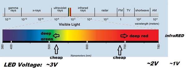
LED color

Without delving into semiconductor physics and such, note that the typical operating LED voltage varies with color.   Cheap red and green LEDs will have operating voltages closer together than Deep red and Deep green LEDs.  And in the circuit you guys are using, the function of D3 and D4 is to separate the operating voltages of Red and Green.  Hence, it could be that Rod is using darker LEDs that already start with a wider voltage separation and hence do not need the 2nd diode.

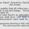
For the prototypical sticklers for detail, you can actually look up the FRS specification for the wavelength effectively specified in nanometers (nm) for Red and Green signals.  Some might find the following clip from 100 years ago amusing.  Given the technology of the day, rather than specifying in terms of nM wavelength as you might find today, note the definition of Green talks of a hint of "blue" meaning to the left of the spectrum as shown above.  In other words a deep green!

admiralty green

If you shop around, you will find interesting names for colors of LEDs such as "Emerald Green", "Pure Green", and so on.  Very few hobbyists, if any, can afford an optical spectrometer that can measure the wavelength of an LED.

Attachments

Images (2)
  • LED color
  • admiralty green
Last edited by stan2004
gunrunnerjohn posted:

For peanuts, you could add a bridge rectifier, capacitor, and 8V regulator.  That would give you universal compatibility.  The 8V regulator is so it would still be compatible with 12VDC with no issues of low input power.

Good plan John and Stan. We already have a bridge rectifier and 220 uF filter cap in the circuit, but a reg would be a good addition. A TO-92 LM7808 would fit with no issues and the 100 ma current limit is plenty for what this circuit is doing. It would be a good addon for the next revision. And we can use one value for R7 that fits all.  Darn, now I need to order some LM7808's.

Rod

Stan, that has to be the difference. My green LEDs are a very light green. The reds and yellows are not what I would call 'deep' colors either, also pretty light colored. I have some better (I think anyway) LEDs from Digikey around here somewhere that I am going to try today and see what happens. One of those may even be an Emerald green, that sounds kind of familiar.

The we_honest signals seem to have somewhat 'deeper' colored LEDs, more so than my cheap LED kit has. For the total signal price, I would expect the we_honest signals to also be using pretty inexpensive LEDs. They so look better than the ones in my kit though. I'm sure they get much better pricing than I do, so they could have the better quality LEDs in their signals and still keep pricing low I guess.

Add Reply

Post

OGR Publishing, Inc., 1310 Eastside Centre Ct, Suite 6, Mountain Home, AR 72653
800-980-OGRR (6477)
www.ogaugerr.com

×
×
×
×
Link copied to your clipboard.
×
×