My DCS-controlled layout has a single TIU, and two Lionel 180-Watt Powerhouse Power Supplies, each powering one of the two channels of the TIU. The layout is divided into two power districts. The frontier of the two districts is insulated with insulating conductors on all three rails. (I know... that's a beginner's error, only the center rail needs to be insulated.) I performed a continuity check and both outside rails are demonstrably insulated. However, the center rail, despite its nylon insulator, is showing connection. It shows connection even when disassembled, meaning that somewhere there is a connection between the two zones. The problem first manifested itself by my locos losing power as they passed between the two power districts. Go slow and they stall at the border. Go fast and they slow down but eventually after about a foot, get enough power to continue on. Both sides of the border are showing 18 volts. Question 1: At the border between the two power districts, the center rail should NOT show continuity on the two sides of the nylon insulator. Correct? Question 2: Any ideas where the connection might be coming from?
Replies sorted oldest to newest
Addendum: Each of my power supplies (via the TIU) deliver power to a 24-port terminal block. From there, each district is powered with 24 direct lines from the block to pigtails located no more than 6' apart.
What kind of track are you using? I had this problem with a Fastrack carpet layout. Somehow the factory-insulated 5" section, wasn't!!
Also, are you measuring continuity with nothing on the rails? A lighted car, loco, or caboose with two pickup rollers can "bridge" the gap.
Thank you Ted!
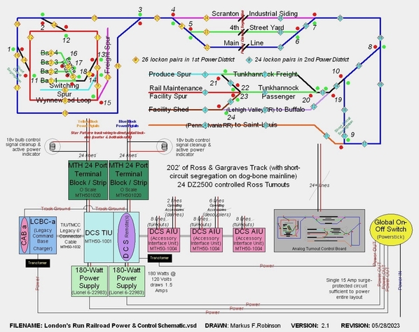
Attached please find a control schematic of the London's Run RR with all key particulars. With respect to your specific questions:
- The layout has 202' Ross & Gargraves track as well as 24 Ross Custom Turnouts.
- I am measuring continuity of the center rail with no rolling stock on the layout at all.
I tore out an entire 36" section of Ross track between the two power blocks and still show continuity between the two blocks now located 36" apart.
All of my track is powered by two star-pattern wiring networks each radiating from one of the two dedicated MTH 24-Port Terminal blocks (one for each block obviously) with power to center rail and common on both outside rails.
I'm at a loss understanding where the continuity connection between the two blocks is coming from. Any suggestions for debugging strategies heartily solicited.
Thanks! Have a great day!
Attachments
The failure symptom that originally provoked this investigation is that when running a loco slowly, it will stall at the frontier and go into the MTH shutdown cycle provoked when the loco is no longer powered. When running a loco fast, it will slow down when it hits the block frontier travel about a foot and then seem to pick up power and signal again and keep going normally. I have removed the beginner's error of insulators on the outer rail commons and am only insulating the center rail. Finally, in the even that this is pertinent... The dogbone mainline would be subject to short circuits at each end loop if they were not isolated as shown on the schematic.
Markus,
To me it appears that you have a phasing problem at the block boundary where the two districts meet. The evidence for this is the slowdown and the one-foot transition before resuming.
if you can fix this phasing problem you might be able to live with the phantom center rail connection until you can find it, which won't be easy because, from the complexity of your schematic, you have many areas to troubleshoot.
To check the validity of the hypothesis that you have a phasing problem put the probes of your voltmeter across the gap in the center rail where you installed the insulating pin (from one side of the pin to the other). If you measure 18 VAC this way then you have a phasing issue and you need to reverse the leads to the lock-ons on one side or the other of the insulating pin. If you measure 0 VAC then we can rule out phasing as a part of your problem.
Mike
The good news regarding debug, is that I have only implemented the Mainline and the 'Thunkhannock' set of spurs. I can disconnect those completely and work just on the mainline, reducing the scope of the continuity bug search.
Hello Mike, Sadly, the issue does not appear to be phasing. My layout power is wired using Star Pattern Wiring. Each of the two Lionel 180-Watt PS 6-22983s powers a single MTH 24-Port Terminal Block, and thence a single pair of 16 gauge stranded speaker wire goes to the 3-pigtail 'lock-ons' (two outside rails tied together, power to center rail) in each of the two power blocks. Measurement across the insulated pin showed 0 volts (well actually 0.1v) while measurement on each side shows 18.9V center rail to outside rails. To educate myself I also switched the polarity of the wires feeding one of the MTH 24-Port Terminal Blocks, and sure enough, I measured 18.9 v on the two sides of the insulating pin. (And since all power to the layout is supplied by a single powerstick (with single global on/off), there is no continuity issue further up the line.)
I've also removed all the beginner error insulating pins on the outside rails of the three locations where the two power districts share a frontier.
So, on to less obvious causes. What do you suggest I try next? Note that I've disconnected all but the dog-bone mainline where the problem is being exhibited.
Perhaps unrelated to this issue. Dogbone loops pose the problem of short-circuits at each of their loop ends. Currently I've addressed this issue by introducing insulated pins on all three rails at one location at each end loop. (see previously posted diagram.) Is it sufficient to only insulate the center rail?
Follow up: While the continuity problem across the boundary remains, magically the initial issue of the train slowing at the boundary between the two power districts has gone away although the loco slows or stalls a slow speeds at other locations on the mainline. Could this be due to the removal of the insulating pins on the outer rails. My track is laid atop foam-rubber Woodlands Scenic track bed. I've discovered places where I inconsistently screwed down tighter into that roadbed causing lows spots. I'm now checking every location along the mainline for
1) all track planar (i.e. level down the track)
2) consistency between connected track sections
3) tight and smooth connections between track segments
4) measuring voltage at each lock-on pin and at the furthest point on each side from each lock-on pin (with the loco on the track in that area to produce a load).
Any other suggestions about how to proceed?
NOTE that at this time, none of my 24 turnouts are powered up. Track at the turnouts is only receiving power from the neighboring lock-ons.
From the lessons learned department: Get one section of track working and fully tested before adding new sections.
Unless I'm reading your diagram incorrectly, it looks like there are actually three (3) separate cross-over points between the two districts - at the Main Line, 4th Street and Scranton crossovers, any one of which, if still connected, would show power in both districts. Are the center rails cut/insulated/disconnected on all three crossovers ?
You said that you, "tore out an entire 36" section of Ross track between the two power blocks and still show continuity between the two blocks now located 36" apart." My guess is that one of the feeds from one of your MTH terminal blocks is connected to the wrong district. I would start by tracing all the feeds from each terminal to make sure there is not one crossed over.
With 3 rail AC powered track you should not have shorts on your reverse loops, no isolating pins are needed. If you are having a short on your reverse loops that is a problem that needs to be corrected!
Thank you Darrel! I had suspected as much but being a DCC neophyte was responding to the warning message generated by the CAD software, Winrail, I used to design the layout. (I never actually experienced any short circuits in the reversing loops of the dogbone mainline.) The design software flagged the necessity of such insulation. That Winrail bug is disappointing since the software allowed the specification of exactly which track was being used. Clearly if two-rail track is being used, there is a problem with reversing loops.
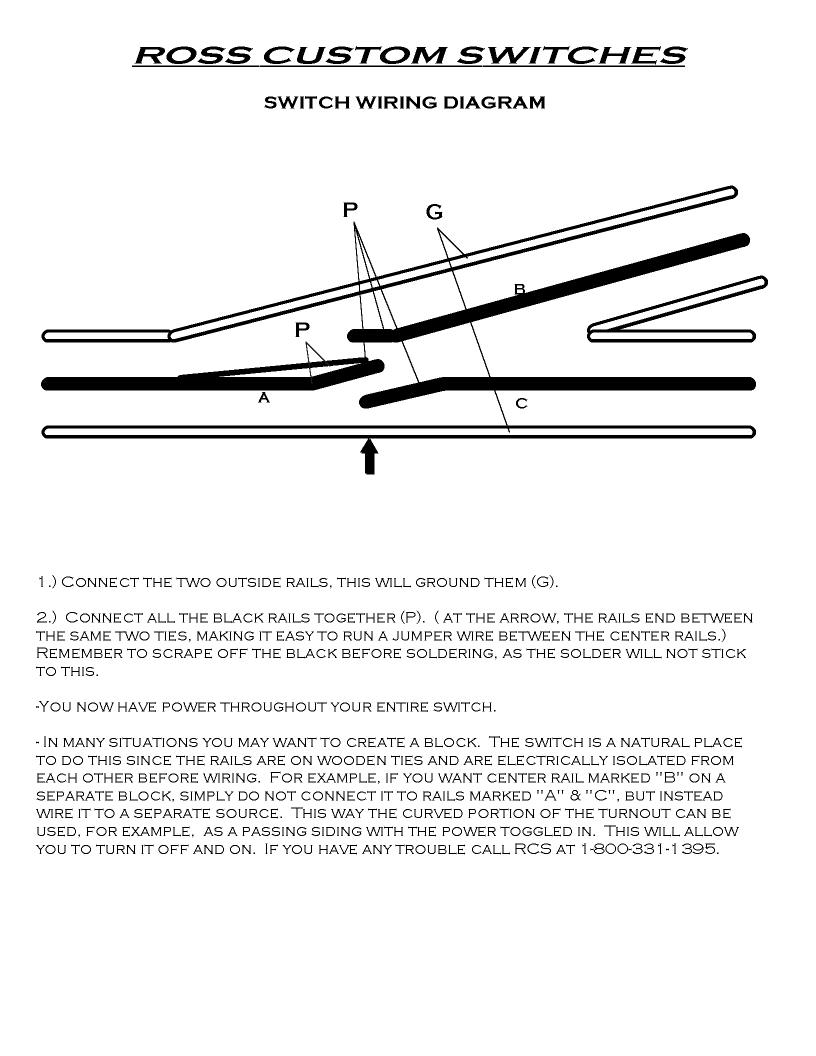
Be aware that Ross switches do not have the outside rails electrically connected together, nor the center rails connected together. So in any crossover, there is no power to either center rail where the turnouts meet. You should check for dead center rails throughout your layout by powering on both districts and checking with an AC Voltmeter the outside rail to each center rail in your turnouts.
While you can use insulators in the outside rails to accomplish the DCS friendly Star Wiring pattern, make sure you have a wire connecting to both outside rails in each block, and additionally where a turnout interrupts the outside rail. You could have a dead outer rail if it is isolated between the "Y" end of 2 turnouts and there is no track feed. This may be the case where your power districts meet.
A loco with widely spaced center pickups may make it through the crossovers, but many will not.
From Ross:

Bob
@RRDOC posted:Be aware that Ross switches do not have the outside rails electrically connected together, nor the center rails connected together.
That depends on what you order Bob. The "Ross Ready" switches do indeed have all the rails connected together.
@Markus Robinson posted:...Clearly if two-rail track is being used, there is a problem with reversing loops.
Yes, that is true in two-rail.
But that problem goes away in three-rail. No need to do anything special with the wiring on a three-rail reversing loop.


