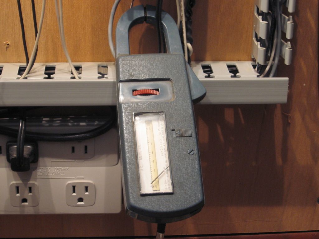
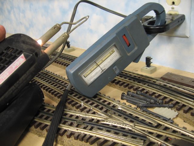
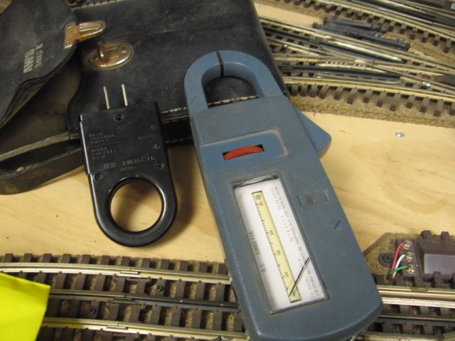
Replies sorted oldest to newest

cjack posted:

Pictures don't help, I don't see where you have the meter connected to anything. Does the 180 watt brick work? Is the track connected to the PM? and the 180 Watt brick powering that?

The brick works fine, the track is connected to the PM. Yes, the brick is powering the PM. I don't have the meter connected as I'm unsure how to connect in this circuit. 

OK. I think you need to encircle a wire going to the center rail with the loop on the meter. Set the meter to the lowest current. What's that little button on the right side? Do you have to press that to read current. And of course, you need to have a load on the track. A passenger car with lighting in it should draw enough current to show a reading on the meter. It probably would read about 0.4 amps AC or so.

cjack posted:

OK. I think you need to encircle a wire going to the center rail with the loop on the meter. Set the meter to the lowest current. What's that little button on the right side? Do you have to press that to read current. And of course, you need to have a load on the track. A passenger car with lighting in it should draw enough current to show a reading on the meter. It probably would read about 0.4 amps AC or so.

I'm unsure what you mean by encircle a wire part, a little clarification please. The button on the side is a peak hold. 

Trainlover9943 posted:

Heres how I have it wired. 

That's fine for reading the voltage. But to read the current, a single wire goes thru the loop. I'm not sure if you know all this or not. Are you really just trying to measure voltage and there is none because the pm or the brick is not working?

To read the current draw, a wire from the power source to the track has to be passed through the loop on your meter, and the meter set to measure current.  Alternately, the meter can be hooked up with the probes by moving the red probe into the far right socket.  One wire from the power source gets connected to the outside track. The other wire from the power source gets connected to one of the meter wires, and the other meter wire gets connected to the track center terminal. The meter must be set to read current before you turn on the power, or you will damage the meter.


Larry

cjack posted:
Trainlover9943 posted:

Heres how I have it wired. 

That's fine for reading the voltage. But to read the current, a single wire goes thru the loop. I'm not sure if you know all this or not. Are you really just trying to measure voltage and there is none because the pm or the brick is not working?

I'm new to measuring current. I've figured I might as well learn sooner or later. I know how to measure voltage, current is all new to me. 

Current is measured indirectly with a "Clamp meter"  the large loop at the top of the meter. 

Measuring the (AC) current two black wires inside the blue loop top of meter. 

There is a loop attachment that allows for measuring plug-in tools, also.  Measuring the AC current used by my soldering gun. 

Older analog meter pictured, new meters have digital displays, but still use the  magnetic loop measure system, which is accurate. 

When all else fails read the instruction book that came with the meter.   Best wishes, Mike CT. 

Meter pictured dates to the late 1970's 

Last edited by Mike CT
Mike CT posted:

Current is measured indirectly with a "Clamp meter"  the large loop at the top of the meter. 

Measuring the (AC) current two black wires inside the blue loop top of meter. 

There is a loop attachment that allows for measuring plug-in tools, also.  Measuring the AC current used by my soldering gun. 

Older analog meter pictured, new meters have digital displays, but still use the  magnetic loop measure system, which is accurate. 

When all else fails read the instruction book that came with the meter.   Best wishes, Mike CT. 

Meter pictured dates to the late 1970's 

Cool. My meter didn't come with instructions I don't think  

Trainlover9943 posted:
Bill DeBrooke posted:

My meter uses the top clamp (loop) to measure amps.  To measure the draw only put the hot wire inside the loop.  Be sure to set your meter on 'amps'.

Volts x amps = watts    

I'll try that. And put the common wire to the track? 

No, you need do nothing with the common wire.  You should be able to get a reading without using, the black and red wire leads, that came with your meter. 

Last edited by Mike CT
Mike CT posted:
Trainlover9943 posted:
Bill DeBrooke posted:

My meter uses the top clamp (loop) to measure amps.  To measure the draw only put the hot wire inside the loop.  Be sure to set your meter on 'amps'.

Volts x amps = watts    

I'll try that. And put the common wire to the track? 

No, you need do nothing with the common wire.  You should be able to get a reading without using, the black and red wire leads, that came with your meter. 

Still no dice. I have it wired correctly right? 

Attachments

Images (1)
  • 20181110_211913
Trainlover9943 posted:
Gilly@N&W posted:

I can't see the rest of that red wire, but no it doesn't look right. With a clamp-on ammeter, the wire goes through the ring. From the picture, it looks like you have the end of the wire being held by the clamp on meter.

Does this looks better. 

Nah, bud that's wrong. You don't clip onto the end of the wire with the meter. Let's simplify this.  Do you have a conventional transformer? Just connect the transformer to your track lockon. Then take your clamp, squeeze to open and the put it over the hot lead. The wire should be passing through the ring like in the picture I posted above.

BOB WALKER posted:

A simple way to measure current is to place a 1 ohm precision resistor in series with the feed from the power source to the load. The voltage measured across the resistor will be equal to the current in amps.

Well, that's "simple", but think about it in the track power application, which is what we're talking about here.  Turns out it's neither simple or suitable.  Simple is the clamp-on voltmeter, just clip it around one wire and take the reading.  No power loss, and no splicing in anything.

Say I'm using, say five amps for my train and supplying the track with 18 VAC.  The resistor will drop 5 volts and I'll only have 13 volts of track power left!  If I used even more power, I'd be dropping even more voltage.  Another point is that the resistor is going to have to be a pretty healthy one, for the 5A example it's dissipating five watts, so it'll have to be at least a 10W rating.

Add Reply

Post

OGR Publishing, Inc., 1310 Eastside Centre Ct, Suite 6, Mountain Home, AR 72653
800-980-OGRR (6477)
www.ogaugerr.com

×
×
×
×
Link copied to your clipboard.
×
×