
I am using LC+2.0 engine with the app. Using a CW80, should I hook up the track to the constant voltage accessory output or the variable track output. Also if hooked up to accessory output what should I set my accessory output voltage to.

Last edited by Frankhpns
Original Post

Replies sorted oldest to newest

Ok, so while you want to run in command mode and desire a constant voltage (ideally 18V AC), we have to also consider times when you do not want power on the track or when problems occur.

If you wire to accessory, it is always on. What about when the train derails, or you need stop to prevent an accident, or you want to change trains, or add cars and not short out the track while adding them?

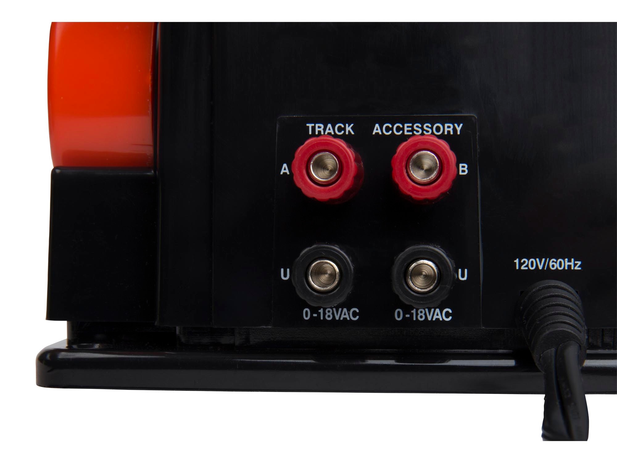
So no, you do not use accessory for powering a track. You use the variable channel labeled track and just raise the handle fully when powering the track, lower it when you need to cut power to the track.

CW-80 80-Watt Transformer

Going further, if you have a derailment or short, hopefully the CW80 current detection trips in the 5 seconds before your wiring or something else burns up. Point being, once that protection kicks in, the reset is lowering the handle back to zero and then raising again. If you used the fixed voltage accessory output of the CW80, then you trip the safety on that output, you have to power cycle the whole transformer (remove AC power from the wall, then powered back on).

So again while technically you can use accessory power, no, that is not recommended for a whole bunch of reasons.

Last edited by Vernon Barry
@romiller49 posted:

If anyone knows please inform as to the breaker reaction time of the CW80. If it’s slow then maybe a 180 brick may be a worthwhile investment to protect in case of derail.

Ron, I covered this extensively when testing the new version of the CW80 and obviously compared it to the old version of the CW80 as a baseline. Bunch of videos of the testing and the details starting here https://ogrforum.ogaugerr.com/...9#161631098285667179

Bottom line up front (BLUF) since the same basic logic was programmed maybe by the same engineer into the design- both basically have the same short circuit response times and other details. Yes, the design of the power stage is different and improved, however core logic and functionality was retained (short circuit, overload, how you set accessory voltage, bel and whistle/horn functions, direction button control).

Also, specific short circuit and overload testing I performed on the new version of the CW80.

Testing using a common 3D printer heated bed that has either 12V or 24V paths. The 24V path is 6 Ohms cold resistance, and the 12V path is 3 Ohms resistance.

Some quick tests using a Fluke 101+ meter (doesn't have AC current measurement so going on voltage over known resistance)
With nothing more than a small light bulb for load output is 18.98V AC RMS max throttle
With the heated bed 6 Ohm load and the lightbulb output dropped to 18.0V and did not trip overload. 18V into 6 Ohm load should be about 3A = roughly 54 Watts
With the heated bed 3 Ohm load, raising the throttle to about 50% on the lever results in 7.5V and not quite tripping the red blinking overload light. Raising it higher to just above 8V triggers the red light overload blink but power is still being provided for 5 seconds. I ran this test several times, a slow load based overload trips in 5 seconds. Just did another reading by removing the load at this setpoint to measure the unloaded voltage VS loaded voltage at the trip point. Test condition throttle at 50% mark, results in 10V unloaded, and then adding the 3Ohm load drops to 8.5V with the light blinking. In theory this is about 3.33A, I didn't have my good ammeter on hand for actual measurements.
The bad part IMO, the overload light blinking starts a 5 second sequence and then power is dropped.

Further short circuit testing:
Raise throttle to 100% with 6 Ohm load plus lightbulb indicator.
Heated bed dual load is approximately 2 Ohms.
Simulate overload with 3 Ohm in parallel to existing 6 Ohm Load= Light dims and voltage is about 9V output, red light blinks, holds load for 5 seconds, then output is off, red light solid. Must turn handle to 0 to reset.
Simulate intermittent short using 3 Ohm load on top of 6 Ohm load. Counting seconds how long the intermittent short is loaded.
This is basically a 2 Ohm load.
1 Second, light blinks, returns green after overload is removed. Power is not interrupted.
2 Seconds, light blinks, returns green after overload is removed. Power is not interrupted.
3 Seconds, light blinks and even if load is removed, continues blinking for 5 Seconds and then power shuts down and red light becomes solid.
Again, the 3 second test, the power continues for 5 seconds and then is shut down.

Using 30 feet of 14 gauge solid house wire as a short load- touching it across the terminals instantly blinks overload switching to solid red and output is shut down.
Again, a very low resistance short results in an instant shutdown.

Further testing accessory side on the New CW80 Fanless transformer:
Works basically identical to the track power side from a safety or overload perspective.
Same set operation at previous CW80. Hold the 3 buttons DIR, HORN, BELL, light blinks green, raise handle to desired accessory voltage, release buttons and lower handle back to 0.
Max voltage with only a lightbulb was 19V.
Set to 12V for testing
6 Ohm load no issue.
3 Ohm load red led blinking and then shutdown in 5 seconds.
Once accessory output is tripped you must power cycle the transformer to reset. -Different than the track power as lowering the throttle to zero will reset a fault on that channel.

Again, my impression is, the new CW80 is an improved design over previous CW models. The new control board design that is fanless is a big bonus and it's not just about removing the fan, the overall circuit is just a lot better. That said, this is still a microprocessor controlled device. The firmware and design decisions put into that ultimately control how this works.
The choice of how to handle intermittent overload and or shorts, and when they trip off VS allowing the load could probably be a multi page debate.
Because the bell and whistle as well as the direction button tell the microprocessor the user input, and then the processor controls the output- there is a delay between user and output. I don't have good numbers on what that is, but it is there- just like the previous CW. That matters to MTH users trying to perform specific bell and whistle sequences.
My gut says that overload works, however, I could also see how you might be able to smoke some thin Lionel lighted car wiring in a derailment. They made and sold both parts of the system- the transformer and the rolling stock, and absolutely, between the thin wiring used for the Fastrack power entry section, to the track joints, to a derailed lighted modern passenger car like a polar express, I'm not 100% sure that the 5 second overload timeout will kill power in time to prevent smoke.

Again, another question asked to me by friends what was the voltage output and as measured, I saw a max of almost 19V, under load dropping to 18.29V.
In theory, overload is kicking in somewhere above 3A and without my good meter handy with an ammeter function, I had to go on measuring voltage across the load and that's not the most accurate method to measure.

My thought is that it's maybe possible with too much accessory + track load to blow the internal fuse that is on the output lead of the transformer before the new control board. I did not try this destructive testing.

I did load the accessory output at 12V setting with the 6 Ohm load, and then applied the 3 Ohm load to the track output at 50% power and tripped the overload red blinking LED and did not blow the fuse and the accessory output and track power both were operating.
I have no concern of it not meeting the labeled 80 watt output. That rating might be combined power and so you may or may not get exactly 80 Watts out of one output or be very close to tripping overload.
I didn't have a fine variable load to achieve that kind of testing.

Also, temperature rise testing since the new one has no fan.

Just for reference, light load testing for temperature of the transformer rise.
I used the accessory output set to 12V RMS unloaded measured with the Fluke 101+ and a small 20ma light bulb just to visually see what the power did or changed.
I used the 6 Ohm load. Ran now for 30 minutes. Transformer is cool to the touch, has not risen in temperature. This was an approximate 24 Watt load. 12v, 6 Ohms, 2A

Pretty impressed that going from the old fan cooled type to this with no vents of any kind, no heatsinks on the FETs, this appears to be a nice cool running transformer.
Again, given I am using the transistors to reduce the output to 12V from the internal 19V, this shows that their switching losses under reasonable loads is very low.
Modern MOSFET tech at work.

Add Reply

Post

OGR Publishing, Inc., 1310 Eastside Centre Ct, Suite 6, Mountain Home, AR 72653
800-980-OGRR (6477)
www.ogaugerr.com

×
×
×
×
Link copied to your clipboard.
×
×