mike g. posted:
Kelpieflyer posted:

Mike,

I like the pneumatic bridge.  I'd love to get the info on it as I think Dad would like to use it.

Thanks,

Russell, shot me an email and let me know what information you would like. I have sent it on to another forum member getting mianne bench work to use with it, he sent it on to Mianne so they could hel with the build.

Mike,

Message sent.

Thanks,

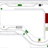
Dad wanted the layout shortened a bit to have more room in the train house.  Here's what I did and also added the crossovers.  Not sure if this is the best way to do it yet.  My concern is that on the top and right hand sides the layout will be against the wall.  I think there may be a problem with the clearance of the outside loop and the top right side of the layout.

Attachments

Images (1)
  • Dads Train House 3
Files (1)
Last edited by Kelpieflyer

That looks like it would work. You would have to put the insulating pin between the two turnout sections at the joint to isolate the loops. I don't know with the Marx switches if you get power to those rails from the switch side. You want to check that out.

You can put the switch and jumper wire for all channel 1 operation anywhere on loop 2 center rail.

I get 4.5" from the center rail to the top wall and 3 3/8" from the center rail to the right wall. I would say it's plenty of space for the overhang of any non-scale engines.

Moonman posted:

I get 4.5" from the center rail to the top wall and 3 3/8" from the center rail to the right wall. I would say it's plenty of space for the overhang of any non-scale engines.

I agree with Carl, I believe you have adequate clearance if the measurements in SCARM are accurate enough.

As drawn, the bench work in the upper left begins near grid mark 64.25" on the "X" axis and goes to 231" making the top length 166.75", slightly less than 14'. My guess is it's supposed to be 14'.

The lower side of the entry starts at about 65.75", a 1.5" difference. FYI

In the lower right, it ends at 135.25" on the "Y" axis making the right side length 11' 4". If it's really supposed to be 11', that's a 4" difference and could affect the clearance of that lower curve.

There are 4 pieces of GarGraves "S" gauge flex track in the design. FYI

Hi Russell,

I am working with someone now on this issue.

The Mianne will always be 1 3/4" longer than the dimension specified as the size is based on center to center of the cross members. it is half of the leg top on each end and half of the outside cross member.

These were ordered on increments 2', 4', and 8'. The problem this creates is a lot of waste from non-standard sheet cuts.

You can custom order the cross member sizes. I don't know if there is an additional cost.

Decide how you would like the finished to look. Then, discuss that with Tim when ordering.

We decided on a fascia board and will fill the gap on top with a cut filler piece or a piece of trim molding for a raised edge to save the waste of sheet cuts.

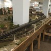
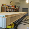
I have attached two photos of forum member's builds to show the edge.

On a side note, watching a Nat geo show, I learned the Scottish meaning of the kelpie - kind of scary that you use kelpieflyer!


Attachments

Images (2)
  • Flyboy62_Mianne_Fascia
  • Putnam_Division_Mianne_Edge
Last edited by Moonman

Russell,

I ordered a kit from Mianne last month and waiting to receive it.  I took the measuring precautions Carl posted, 1 3/4" longer.  My intent is to have the top board extend out over the edge of the benchwork a few inches and the sides will fit my space nicely.  I use a hodge podge of cut pieces of board, so the odd measurement doesn't matter to me.  I want the front to overhang about 6 inches so I am not kicking the legs all the time.

Most people I have seen have done it like Carl showed.  I have to be different, I know!  

Carl,

Thanks for the benchwork insight.  I'll keep it in mind with my discussions with the guys at Mianne.  The Mianne guy also told me that since Dad wants a bit of space to sit next to the layout that we may incorporate a type of cantilevered design to prevent the plywood from warping over time.  I do like the fascia that is on the layout.  I'll see if Dad wants that.  We have a bunch of 3/4 inch plywood from Dad's old layout that we can reuse.

The Scottish Kelpie is a creepy one....  I have never heard that one before. Kelpie is a name my wife thought up because I like to mess with kelp that washes up on the beach.  Of course, Kelpieflyer can also refer to a Scottish Pegasus or maybe a flying fish or Screeching Eels from Princess Bride?

Last edited by Kelpieflyer
Kelpieflyer posted:

The Mianne guy also told me that since Dad wants a bit of space to sit next to the layout that we may incorporate a type of cantilevered design to prevent the plywood from warping over time. 

I know they offer a cantilevered system for a 2nd level, but I can't envision what they mean here, so I'll be interested to see. I'm also curious to see how they handle the angled section.

Kelpieflyer posted:

Carl,

Thanks for the benchwork insight.  I'll keep it in mind with my discussions with the guys at Mianne.  The Mianne guy also told me that since Dad wants a bit of space to sit next to the layout that we may incorporate a type of cantilevered design to prevent the plywood from warping over time.  I do like the fascia that is on the layout.  I'll see if Dad wants that.  We have a bunch of 3/4 inch plywood from Dad's old layout that we can reuse.

The Scottish Kelpie is a creepy one....  I have never heard that one before. Kelpie is a name my wife thought up because I like to mess with kelp that washes up on the beach.  Of course, Kelpieflyer can also refer to a Scottish Pegasus or maybe a flying fish or Screeching Eels from Princess Bride?

Since you have the 3/4" ply to use, it shouldn't need any support. I would venture to say that you could go a foot on the overhang and still stand on it. Perhaps a support would be needed because of the minimal fastening at the leg tops only. Like Dave, I would be interested in their idea. Some locking triangles on pins would do it.

Phew! Glad to hear it wasn't a reference to mythical beasts.

Screeching Eels! Inconceivable!

  I only know of the "evil" kelpie, a shape shifter, but normally a horse if an animal; an evil spirit that would drown you any way it might manage to.  Am I sensing another story?  

  Some eels do make some noise; more like a pitchy grunt than a screech. Or is that lung fish? 

The only thing you can do about it is make some sushi rolls while the kelp and eel are still fresh... (ha, made you read it   )

Nice touch, matching the legs to the trim. 

If you phase the transformers you only need one common and a hot (3) for each line - pull a bus from end to end and tap into it for track feed where needed.

3M tap splice

You could also add one or two Accessory bus wires for say switch power and light voltages. 14awg also.

Use 12awg for the common as it would carry all of the current of the 3 lines and 14awg for the hot bus wires.

Kelpieflyer posted:

I plan on setting Dad up with remote operation so he doesn't have to be next to the transformer.

Setting it up like this:

 https://ogrforum.ogaugerr.com/...85#81819043047937385

I would like to have three separate power blocks.


Well, then you have to get the gear first and that will determine the best way to wire it - the guys gave you all of the combinations of Lionel or MTH gear - the plan I gave you was for straight transformer operation with three transformers on AC output

Last edited by Moonman

Add Reply

Post
The Track Planning and Layout Design Forum is sponsored by

AN OGR FORUM CHARTER SPONSOR

OGR Publishing, Inc., 1310 Eastside Centre Ct, Suite 6, Mountain Home, AR 72653
800-980-OGRR (6477)
www.ogaugerr.com

×
×
×
×
Link copied to your clipboard.
×
×