


I'm currently working on a new layout using all Atlas O track. I also plan to use DCS on the layout. I'm using the Atlas O wired terminal joiners for the feeds for my track power at each block. I plan to run 14 gauge wire out to the feeders. The wire on the Atlas terminal joiners seems to be 20 gauge. Per Barry's book, this may be a problem for a good DCS implementation. Has anyone successfully used the Atlas terminal joiners with a DCS implementation. Appreciate any feedback.
Original Post


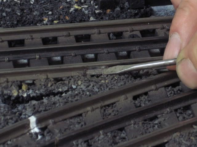


 I took some new joiners and soldered 16ga wire to them.

