Let me start with DCS was up and running on what track I had put down for testing. It was a substantial amount (>30 feet)  ran two ps3 diesel engines on same track using DCS handheld remote controlling both at will. Things seemed to work as designed so the next step was to connect Lionel legacy to the system so I could use the MTH remote to control a couple of Lionel/ERR upgraded engines as well as the MTH diesels. Hooking up all the correct cables and LCS serial2 box I was able to get the lionel upgraded diesel (Illinois Central 2363 post war unit) to run under MTH DCS handheld remote. Sounds all good... well then murph the surf shows up! I put the mth diesels back on the track, power up and they are dead as door nails!   So of course what was the last thing I did? Lionel Legacy added. So I removed the legacy fro the system and still dead as door nails, I hit the read button and it shows 1 tiu and 3 Aiu's and no DCS engines detected.   After removing two of the three input/outputs so there was just fixed 1 input/output, same thing would happen, nothing! Ok so I take my spare TIU which both of my TIU's are rev. L , and a separate piece of track and put my mth SW-1 penn switcher on and it is inactive. Hit read and it shows 1 TIU 0 AIU's and no engines connected. Just to see if anything would work I set up the DCS consumer loader and copied the handheld remote to the pc. That worked! Then I down loaded the sound file from the engine (SW-1) to the PC and that was succesful (114 minutes later) . I swapped engines with the second ps3 engine and upon powering it up, there was life! Not sure why yet... ok with the remote I was able to shut it down, start it up, move forward, change direction, move backwards, so it seemed to be working. I put it back on the main layout and it appears to still function! ok good news! Murphy comes back and I hit read, just to see what happens. it finds 1 TIU 3 AIU's and no dcs engines found! And now the engine is in the inactive list and cannot be controlled. So I power everything down, track, TIU, AIU, and handheld remote. Power it back up and it all functions again! However this time I start the engine moving forward and then hit read as it is moving. Yup no dcs engines found, the engine that is still moving down the track is no in the inactive list and cannot be controlled! I shut down power to everything which was the only way I could stop the moving engine. Powered it all back up and it all works again. I leave the read button alone and shutdown engine and turn off power.

Can anyone help with this??? The SW-1 is on a test track with different TIU and is still dead to the world, although the pc thinks it downloaded its sound file. I am totally new to DCS, I did look through the troubleshooting and this isn't mentioned. I have read several posts alluding that the no engine found is low DCS signal from TIU however from both TIU's??? The second TIU is literally brand new, almost never used.

So questions in my mind are: On power up it reads the engine, but hitting the read button the engine is not found. What is the difference???

And should I try to flash the engine that is dead operationally but seems to transfer files fine.

Any help it appreciated! Thanks in advance. Sorry for being LONG Winded

Last edited by Aegis21
Original Post

Replies sorted oldest to newest

20 years with DCS and still learning. Even though one TIU is on the layout and one you were using as a test track. They weren’t both powered up at the same time in your last scenario and the remote is seeing 2  #1 TIU addresses. But in the beginning you were only dealing with the one on the layout. Whenever I have issues. It’s usually battery related. With PS3 engines it should rule that out. Most times I just delete the engine and start over and re add it.

I’m not one that usually presses the read button unless I’m having an issue.  Don’t think I ever did it with a moving engine. If you have a really bad track signal. It may not see the engine when you press it. Remember. Once an engine gets moving. Even if you lose control of it. It will always  follow the last command it received. I think by pressing it. The only reason for an engine to go on the inactive list is it’s either not on the layout or it’s on an unpowered track with say a toggle switch. It only reads what it sees. If you manage to get it up and moving. It wouldn’t hurt to do a track signal test just to see where you stand. A lousy signal can make it hard to run anything reliably.

Please purchase the DCS O Gauge Companion from the MTH website. I assume that the wires are minimum 16 gauge stranded (18 gauge produces the results that you are experiencing).      

Hi Gerald,

The wires are 16 ga. and have the DCS O Gauge Companion from MTH which I have been using to electrically set up the entire layout. Using star wiring for power feeds to various districts. Always good to check fundamentals.

And Dave C. good point on engine just using the last command, I was thinking that there was always communication between the engine and tiu (throw back to guided missile days where you had to keep communications between the ship and nuclear guided misslie) Yes it makes sense that the last command is what it follows until the next command is ack.

@Porschev posted:

Make sure you have correctly installed 22 uH chokes in any Lionel or ERR upgarded locomotives otherwise they will kill the DCS signal.

I will double check, I did the "upgrade" so long ago I cannot remember if the chokes came with kit and where they would go. However I have the original documentation and any parts that were not used in a separate container. So I should be able to check that out for sure.

I did have the tracks cleared of any lionel engines when I was having DCS issues with finding engine and doing a read. Thanks for the great suggestion when I do have both MTH and Lionel on the layout.

Ok so what I found was terrible DCS signal on the layout track. (3-5) were the numbers until the engine got close to the track with the actual feed wires, then signal went up to 8.

The test track did have signal of 10.

Also when I turned on my remote 'BAT' came up, which I assume is low battery alert and I changed the batteries.

So I will need to work on getting the DCS signal up to snuff on the layout before I continue doing any other work. Back to reading Barry's book. Not sure why the signal is not a 10 on the track with direct wiring. The TIU is a Rev. L and the output of the TIU goes to a relay board then to the track. I might try by-passing the relay and test the signal again.

My layout features pretty much violates all the rules of DCS. Common ground buss wiring and feeders in every section of track. Layout had been around for 15 years before DCS. After a months tweaking after the initial install it yields 10’s everywhere. Still if I was starting from scratch. I would follow the recommended practice with the paired wiring.
Not sure how you have the relay board wired. When I wanted to have tracks with on off capability. I pretty much wired as I normally would. Then just cut the center rail wire somewhere near where the toggle switch would reside and place the relay there.  This would not alter the direct run to the track from the terminal strip. The relays were just controlled by a 12v power supply that was already there for the Tortoise’s and lighting.

One thing DCS doesn’t like. Is splitting the signal more than once. You want your paired wires from the TIU to go to a terminal strip. From there they should only go to a section of isolated track or a block. Not to another strip and then split again. It’s pricey but the one MTH sells works well for this. Add one block at a time and keep checking your signal. The signal will only cover so much track before it sort of maxes out. They give you 4 channels to use. Use 3 and it’s nice to have one as spare where you can just switch wires over if needed. When the layout gets to large. There’s always Super TIU. But I agree. You should see a 10 on one block during testing if that’s all that’s powered up. You can see a few blips at times. I wouldn’t worry to much. My layout is all Gargraves flex. I can see 10’s in a 3 foot section but every now and then it may pop a bad number. In that case it could just be some crud on the track or something. What you want is consistency through each section.

Are your connections from the TIU to the distribution board tight ? I like using solder-type "gold" plated banana plugs. I dislike using the "screw" type.

What about the feeder connections from the board to the track - are they solid at the track ? Soldered ?

If the signal gets stronger as the engine gets nearer the feeder wire, it might mean the DCS signal is not propagating very well along the rest of the track rail. Are your track joint connections tight ? Is the track clean ?

How far apart are the track feeders ? Do you have enough ?   

Last edited by Richie C.

When you hit the read button it puts all DCS engines into inactive state    They should be dead until you do a startup     Make sure you scroll all the way down on your remote into the inactive list   Highlight the one you want to startup and press the thumbwheel   It will move that engine into the active list   Then hit startup 

Please purchase the DCS O Gauge Companion from the MTH website. I assume that the wires are minimum 16 gauge stranded (18 gauge produces the results that you are experiencing).      

Are you saying even the drops need to be 16 ga. ? I started using 18 ga. for the drops that go from terminal bd. to track ground and the same for hot wire from relay to track. Wire to relay is 16ga.

@bluelinec4 posted:

When you hit the read button it puts all DCS engines into inactive state    They should be dead until you do a startup     Make sure you scroll all the way down on your remote into the inactive list   Highlight the one you want to startup and press the thumbwheel   It will move that engine into the active list   Then hit startup

I did not realize read button put all DCS engines into inactive. I was under the impression it just read which engines were on the track receiving signal.

@Richie C. posted:

Are your connections from the TIU to the distribution board tight ? I like using solder-type "gold" plated banana plugs. I dislike using the "screw" type.

What about the feeder connections from the board to the track - are they solid at the track ? Soldered ?

If the signal gets stronger as the engine gets nearer the feeder wire, it might mean the DCS signal is not propagating very well along the rest of the track rail. Are your track joint connections tight ? Is the track clean ?

How far apart are the track feeders ? Do you have enough ? 

To answer your excellent questions. I have some expensive/high grade screw gold banana plugs. Screws and offset and 180 degrees opposite and have excellent conductivity.

Feeder connections are solid 14ga. from TIU to remote TB then 16ga. to relay (that controls block power) and 16ga. to track outside rail which the connections to the track are soldered.

Now you hit on some problems with track connections, cleanliness of track. This was only a temporary hook up to get an idea on how layout will look and if my design on paper matches my design in my head. So connections were not a priority. That said, the best signal I can get with engine on the track with soldered connections that I just cleaned is between 7 and 9 (not a 10 to be found) It is a 37" gargraves flex track. I'll double check the connections to the TB and relay. Also relay contacts. I may temp. by-pass the relay just to eliminate that as a suspect.

Thanks for your help.

@Aegis21 posted:

I did not realize read button put all DCS engines into inactive. I was under the impression it just read which engines were on the track receiving signal.

The read button looks at your equipment   For an engine to be active after the Read it needs to be powered on and started up otherwise it is considered inactive and it is moved to the inactive list   If the engine is just sitting on the track not started up its inactive   If you didnt hot startup button and have the engine idling with sounds on its inactive

@Dave_C posted:

One thing DCS doesn’t like. Is splitting the signal more than once. You want your paired wires from the TIU to go to a terminal strip. From there they should only go to a section of isolated track or a block. Not to another strip and then split again. It’s pricey but the one MTH sells works well for this. Add one block at a time and keep checking your signal. The signal will only cover so much track before it sort of maxes out. They give you 4 channels to use. Use 3 and it’s nice to have one as spare where you can just switch wires over if needed. When the layout gets to large. There’s always Super TIU. But I agree. You should see a 10 on one block during testing if that’s all that’s powered up. You can see a few blips at times. I wouldn’t worry to much. My layout is all Gargraves flex. I can see 10’s in a 3 foot section but every now and then it may pop a bad number. In that case it could just be some crud on the track or something. What you want is consistency through each section.

Hi Dave, First thanks for responding. The output of my TIU goes to a distribution TB and that connection is less than 12" (more like 3"-4") each TIU output supplying one district TB. Then it splits to three remote TB's that are separate power blocks. (star wiring method, I think) From each of those are the connections to the tracks made, comm is direct and hot is relay switched.

I am using three TIU outputs, one for each district (3 districts and one unused) Var1 is district 1, fixed 1 is District 2, fixed 2 is District 3, with the forth as a spare. I also have the Watch Dog boxes attached to the distribution terminal Bd. near the TIU's. Maybe I did not make those correctly. Those I'll disconnect when I do the relay by-pass to see if the relay is causing and issue. I won't need the WD with a direct connection to TIU.

Thanks

@Porschev posted:

Make sure you have correctly installed 22 uH chokes in any Lionel or ERR upgarded locomotives otherwise they will kill the DCS signal.

Well I am 90% sure I did not install 22 uH chokes in my Lionel ERR upgrade. I am going by the directions I followed for installing the AC commander board and rail sounds board. They only had me put on the motor two capacitors. So where do the chokes go and where can I buy them?

@bluelinec4 posted:

The read button looks at your equipment   For an engine to be active after the Read it needs to be powered on and started up otherwise it is considered inactive and it is moved to the inactive list   If the engine is just sitting on the track not started up its inactive   If you didnt hot startup button and have the engine idling with sounds on its inactive

Got it now! Thanks for the clarity.

@bluelinec4 posted:

The read button looks at your equipment   For an engine to be active after the Read it needs to be powered on and started up otherwise it is considered inactive and it is moved to the inactive list   If the engine is just sitting on the track not started up its inactive   If you didnt hot startup button and have the engine idling with sounds on its inactive

Actually, any locomotive that is powered up and seen by the TIU will be left on the active list.  I just tried it to make sure my memory was correct.  Both the one that was started and the one that was just powered up remained on the active list.  The engines not powered up were indeed moved to the inactive list.

Actually, any locomotive that is powered up and seen by the TIU will be left on the active list.  I just tried it to make sure my memory was correct.  Both the one that was started and the one that was just powered up remained on the active list.  The engines not powered up were indeed moved to the inactive list.

Ok what is the difference of one started and one just powered up? I am getting lost in the terminology, being a total newbie to modern day model train technology.

The logic behind the above statements and why it matters:

While DCS is a signal on the track, it is bi-directional meaning the TIU talks to the loco, and the loco talks back to the TIU.

An engine must have track power- to be able to respond and reply back to a DCS command back to the TIU.

An unpowered engine (engine sitting on track that is not powered at the moment) cannot reply- to a read request- hence is "not on the track" hence is deemed "inactive".

An engine powered on the track, but not started, sitting idle, no lights, no sounds- still is possible to respond to DCS commands because it does have track power.

Last edited by Vernon Barry

The logic behind the above statements and why it matters:

While DCS is a signal on the track, it is bi-directional meaning the TIU talks to the loco, and the loco talks back to the TIU.

An engine must have track power- to be able to respond and reply back to a DCS command back to the TIU.

An unpowered engine (engine sitting on track that is not powered at the moment) cannot reply- to a read request- hence is "not on the track" hence is deemed "inactive".

An engine powered on the track, but not started, sitting idle, no lights, no sounds- still is possible to respond to DCS commands because it does have track power.

These are concepts that I have read about, however haven't remembered. The last one does take me aback a little, as I am used to seeing some "life" a light or sound when a track is powered. Obviously old old school...

@Aegis21 posted:

These are concepts that I have read about, however haven't remembered. The last one does take me aback a little, as I am used to seeing some "life" a light or sound when a track is powered. Obviously old old school...

Yep, old school, at least when it comes to DCS.  Most DCS engines are totally dark and silent until started.  Some Lionel engines are as well, but many newer Legacy engines drive the number boards directly from track power.  In a way I like that for the reason you state, I can see the track is powered.

Yep, old school, at least when it comes to DCS.  Most DCS engines are totally dark and silent until started.  Some Lionel engines are as well, but many newer Legacy engines drive the number boards directly from track power.  In a way I like that for the reason you state, I can see the track is powered.

Yes an indication track is powered by using number board is what I guess I was and still look for...   How foolish lol

John, I took the liberty of using one of your photos to show your setup from your build thread.

926E9400-76F8-4803-A522-80AA28DD37CF

It looks like you have 4 outputs at the terminal strip for each of your 3 channels. For testing purposes. Can you easily run the paired wiring from your piece of Gargraves track. Direct to this terminal and by pass your relay board. Your track should yield a 10.  If not try another channel or put a lightbulb across the terminals and see if the Magic Bulb makes any difference. Shouldn’t be any issues if it’s a new one. Then try adding a few more sections and keep checking your signal. After you have a few sections hooked up and you are seeing 10’s. Then go back and hook up your relay board and check again. I think it’s best to hook DCS in it’s simplest form and then add to it.
As far as hookups to the tracks. I’ve seen alligator clips used for testing and work fine or just solder the wire to the track pins. I think it’s beneficial also to jumper the outside rails. Soldered wires work best or shove a spade connector into the Gargraves track web. You will need needle nose pliers to push it in. Should sort of snap in with a click. I use non insulated ones. I also use 14 gauge wire. 16 is probably fine for this.  I just find it easier to push these in place and then solder the spade to the rail and the wire to the spade. Just frees up your hands while soldering.

Just curious on how your relays are wired. I’m guessing your turning them on with a separate DC power supply through a toggle switch and what’s going to the center rail is going through the contacts.

Attachments

Images (1)
  • 926E9400-76F8-4803-A522-80AA28DD37CF
Last edited by Dave_C
@Dave_C posted:

John, I took the liberty of using one of your photos to show your setup from your build thread.

926E9400-76F8-4803-A522-80AA28DD37CF

It looks like you have 4 outputs at the terminal strip for each of your 3 channels. For testing purposes. Can you easily run the paired wiring from your piece of Gargraves track. Direct to this terminal and by pass your relay board. Your track should yield a 10.  If not try another channel or put a lightbulb across the terminals and see if the Magic Bulb makes any difference. Shouldn’t be any issues if it’s a new one. Then try adding a few more sections and keep checking your signal. After you have a few sections hooked up and you are seeing 10’s. Then go back and hook up your relay board and check again. I think it’s best to hook DCS in it’s simplest form and then add to it.

yes I will do exactly that, running a line from District 1 to TB 1 and connect the drops from the track directly to TB 1 thus eliminating the relay as an issue.


As far as hookups to the tracks. I’ve seen alligator clips used for testing and work fine or just solder the wire to the track pins. I think it’s beneficial also to jumper the outside rails. Soldered wires work best or shove a spade connector into the Gargraves track web. You will need needle nose pliers to push it in. Should sort of snap in with a click. I use non insulated ones. I also use 14 gauge wire. 16 is probably fine for this.  I just find it easier to push these in place and then solder the spade to the rail and the wire to the spade. Just frees up your hands while soldering. Interesting way to connect the wire to the tracks. I will certainly give this a try.

Just curious on how your relays are wired. I’m guessing your turning them on with a separate DC power supply through a toggle switch and what’s going to the center rail is going through the contacts. Relay is wired wiper to TB hot and normally open contact goes to middle rail. The relay coil gets dc from onboard ac to dc supply, to power a micro controller that controls relay. Although the ac supply  is from the the block terminal board. This is I believe isolated but when I by-pass the relay I will also remove the micro controller board (with ac to dc power supply) on it to confirm it is not also an issue.

One other thought, since that pic was taken I have wired led's across each district to indicate power is on that terminal strip for each district. Maybe and issue also!

Last edited by Aegis21

I’m far from an electronic whiz at these things. If I understand your post. Your using the AC track power at the terminal strip that also is carrying the DCS signal to turn your relays off and on.
Are you turning them on and off using an AIU ?   Usually when using a relay you opt for a separate DC power supply. I know the first rule is to not rely on track power to power your turnouts if it’s also carrying the signal.

Hi Dave,

I am using track power to power a dc supply which feeds the micro controller that energizes the relay coil. The AIU Does control the relay by way of a micro controller piggybacked onto the AIU. The micro controller monitors the AIU for a relay activation and over the air (no wires) sends that signal to the remote micro that controls the relay for block power. I could run a seperate bus line to send ac around the layout independant of the TIU for such uses. I know I have made it more complicated than it needed to be.

Try the magic light bulb trick. Put an 18v light across the track at the feed point. Improves track signal. Alternate to Magic light bulb is the susan deats filter.

On my layout, The TIU flashed the internal LED three times. The Remote read TIU as one. When I got them both synced to one, DCS ran much better.

John, I would go from your terminal strip to one piece of Gargraves track. No relays or anything else in the equation. See what you get for a signal. You should get a 10. You are pretty much just creating a programming track which usually yields one. Now add a couple more sections. You will have a 9 foot block and if you are still seeing 10’s. Now go back and put your relay board and test again. If the signal goes south. You will have to address the relay board. Not sure if a separate power supply to the board will fix it.  I showed a picture of your setup. Unless you are stacking wires on your terminal strip. It looks like you only have 9 wires to use from your TIU channels. I’m not seeing the relays outputs. Once you split the wire coming out of one of your TIU’s  channel the 3 times. You can’t split it again after comes out of your relay.
My own layout was pretty much non functional with DCS. I ran TMCC but it was basically wired like a conventional layout. Lots of toggle switches, track signals using ac relays, and even relay banks to allow for a more automatic running if guests were over. So when I hooked the DCS up initially. It somehow allowed me to add an engine. After I got it moving I had very little control of it. Did a signal test and got one 8 and a bunch of 2’s and 3’s. My first quest was to run a paired wire over to a turntable whisker track. Nothing else was powered. I saw a 10 so I now knew one existed. I focused on one block at a time. In a months time I got all the gremlins out of it. Had 10’s everywhere. Pretty much just removed all the complicated wiring.

What I learned was at least on my layout. DCS likes simplicity. Wires from the TIU outs to a terminal strip. Even though my layout was wired totally wrong with common ground wiring. It worked. I think the 12 gauge buss and 14 gauge feeders may help. I did a new section and did adopt the paired wiring with good results.

Last edited by Dave_C
@gftiv posted:

Try the magic light bulb trick. Put an 18v light across the track at the feed point. Improves track signal. Alternate to Magic light bulb is the susan deats filter.

On my layout, The TIU flashed the internal LED three times. The Remote read TIU as one. When I got them both synced to one, DCS ran much better.

I do not have an 18volt light bulb on hand. I will look into procuring one to try, although my TIU's are both

rev. L , which I read somewhere the bulb has little impact. Although it is certainly an option I will look into.

Hello All,

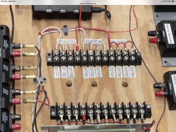
First thanks for all the help, education and general information concerning my issue and DCS in general. I pretty much followed what Dace C. suggested. I left all the track connected about 35 feet. (yes I know that will not be the length of my block on the layout) That will setup a worse case test,  signal at zero feet, 3 feet, 6 feet and so on. I did take off the wire from the track to the relay and directly hooked it up on the supply terminal board. At the same time I disconnected the relay board from the supply terminal board. Turn on system, it found the engine, it was on the track that has the feeder wires soldered on, so basically a test track position. Viola! 10's on dcs signal. ok now I started engine down the track at speed number 3 and it went registering 10's all along the way till the end, 35 feet away. There were one or two 7's and 8's, but I can believe that was dirt on the track. Next step was to re-power the relay board. Retest results were 3's, 4's and 5's even at track zero! So next step was to bring in another transformer to power the relay board and connect the center rail feed wire through the relay as designed. Re-test showed again all 10's for 35 feet!  So I need to run a separate  pair of 19 volt ac as accessory/relay board power bus.

Here are some pics: Control panel DCSIMG_5328

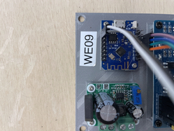
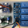
Relay section of remote control module IMG_5331

Power supply and micro controller power supply is lower unit in this pic and micro controller is upper unit with antenna on printed circuit board.IMG_5330

Again THANKS for all the help. I will now have to do things in steps and test after each step. Like adding more blocks, switches, accessories etc.

Attachments

Images (3)
  • IMG_5330
  • IMG_5331
  • IMG_5328

  John, glad you got it working.  The track signal test is probably the most important feature of the system. I don’t know what you would do without it.  Now that you have one section working as it should. It’s easier to proceed forward with the rest. Anyone building a layout and incorporating it should constantly test as you add. When your signal goes south. You can always revert back to the last thing you changed or added. Those with existing layouts it’s a little harder. You just have to take small steps focusing on one loop or one block at a time.

@Dave_C posted:

  John, glad you got it working.  The track signal test is probably the most important feature of the system. I don’t know what you would do without it.  Now that you have one section working as it should. It’s easier to proceed forward with the rest. Anyone building a layout and incorporating it should constantly test as you add. When your signal goes south. You can always revert back to the last thing you changed or added. Those with existing layouts it’s a little harder. You just have to take small steps focusing on one loop or one block at a time.

Excellent advice which I will adhere to! Again Thanks Dave!

Are you saying even the drops need to be 16 ga. ? I started using 18 ga. for the drops that go from terminal bd. to track ground and the same for hot wire from relay to track. Wire to relay is 16ga.

Drops should be 16 gauge.

Not really.  I used #14 for my main power feeds and #18 for the track drops.  IMO, even #18 is more than sufficient for the short drops from the track.  There's no reason to get carried away.

Holy DCS Batman! This is getting extremely old extremely fast. So the system is as follows: DCS was the only player on the layout. District one with 70 feet of track only one connection to TIU, ran signal test with MTH engine and got all 10's except for one spot which dropped to a 7 and an 8. So being happy with that performance for two days I would run that engine up and down the track and check signal which always resulted in getting 10's. (I cleaned the offending track) Now things get interesting. I hook up Lionel Legacy unit to system with the proper cables from MTH Serial cable from Legacy to TIU and one wire from legacy to third rail. Then put on track the ERR upgraded engine to run with the legacy controller. Power it all up, light comes on the engine and I throttle up and the engine moves forward a bit, sputters then stops with light out. Meanwhile down track a MTH engine starts some station chatter and comes to life. ????  Shutting power off and then back on still does not get the lionel engine light to come on. Yes I moved it to another section of track just to be sure to have clean track under it. So I take the engine back to the single test track I have set up with TMCC cab1 and engine functions as it should. Ok so I maybe dealing with one system killing the other. Getting back to the main layout, I disconnect the lionel legacy connections and check out the MTH Engine still on the layout track. It gives no response. I delete it from the handheld and try to enter it back in and of course it gives no engines found. Hmmm.... So I take the other handheld, turn it on and it works the engine forward/reverse shutdown/start up. I even check track signal and get 10's So I change batteries in the other remote and with the engine started up I try to add it to the remote. No Engine Found  huh! I can control it with the other remote, have signal of 10 and it can't find it. So I foolishly power the remote that has control and delete the engine from it so I can see if the problem is only the other remote (lets call problem remote remote#2 and functioning remote remote#1) So I delete that engine from list and try to re-enter it and No Engine Found.... Put another MTH engine on track it both remotes can control it. I don' dare remove it from the remotes at this point. Best guess on my part is the Lionel test messed up the MTH engine on track. Mind you I was not programming that engine, just trying to control it.  Things I can do are : reload remotes and see if I have control of the "faulty" engine (RS-3 Erie Lackawana 1057)  re-load engine, (not sure what files to re-load on it)

This is frustrating as I have been wiring things by the book, so to speak, and it appears every step is like running through a molasses pond in January. No doubt I am doing things incorrectly, and want to find out what my bad practices are and stop them now. It seems this happened before on one of the MTH engines. Is this common? Help !!

@Aegis21 posted:

Now things get interesting. I hook up Lionel Legacy unit to system with the proper cables from MTH Serial cable from Legacy to TIU and one wire from legacy to third rail. Then put on track the ERR upgraded engine to run with the legacy controller. Power it all up, light comes on the engine and I throttle up and the engine moves forward a bit, sputters then stops with light out. Meanwhile down track a MTH engine starts some station chatter and comes to life. ???? Shutting power off and then back on still does not get the lionel engine light to come on. Yes I moved it to another section of track just to be sure to have clean track under it. So I take the engine back to the single test track I have set up with TMCC cab1 and engine functions as it should.

This sounds more like a power event than anything else.

What appears to have happened- the ERR engine overloaded or shorted your power supply. That power then returned and the DCS engine on the same power district/channel then missed the watchdog and started up in conventional.

This same power event then might have killed or damaged DCS signal.

Actually, the more I read this, your mainline track sounds like it has some problems. one possible answer- I don't know your track feed or your track system of joints (rail joints, pins or joiners) but that sure sounded like dead sections of track power. So badly so, as the engine rolled- one section lost power and another section the MTH train was on ALSO power cycled sans watchdog signal. Things that could allow that is a track system depending heavily on the rail joints to carry the power with few feeders and loose track joints. As the train rolls and draws current, it also can ever so slightly move or shift the rail and thus the loose joints at the ends of the track spark and go high resistance.

Last edited by Vernon Barry
@Aegis21 posted:

That doesn't sound good. Why does the TMCC engine work fine on test track? And the MTH engine worked fine with one control but not the other and neither can find that engine on track. Puzzling to me.

@Vernon Barry posted:

Actually, the more I read this, your mainline track sounds like it has some problems. one possible answer- I don't know your track feed or your track system of joints (rail joints, pins or joiners) but that sure sounded like dead sections of track power. So badly so, as the engine rolled- one section lost power and another section the MTH train was on ALSO power cycled sans watchdog signal. Things that could allow that is a track system depending heavily on the rail joints to carry the power with few feeders and loose track joints. As the train rolls and draws current, it also can ever so slightly move or shift the rail and thus the loose joints at the ends of the track spark and go high resistance.

Again, I would run under conventional first, ensure some of this is not track power and joints and feeders FIRST, and then go down the path of trying to troubleshoot DCS and TMCC/Legacy.

That sounds reasonable to make sure connections are solid. I will get an engine that is just conventional and run it back and forth and see how it performs. Measure track voltage and farthest points and note the drops.

Todays configuration of track is basically one long separate track that gave DCS signal of 10's all along the entire track. When running just the DCS engine I have had no problems (once that track was isolated like it is presently)

I understand the extra load with the old lionel engine (1958 Berkshire 736 steam converted with an ERR Ac Commander) could be the load that broke the connections between tracks. There is always the track (37" gargraves)  that has the feeder wire soldered onto it that could eliminate track resistance as a culprit. I could put the engine on that track and do the same test without another engine on the layout. Does that sound like a good step?

@Aegis21 posted:

Only one outside rail is connected to common.

That would be top of the list things to fix.

I know you may not understand, but that perfectly explains most of these issues.

#1 many MTH engines that have 2/3 rail capability may not pick up on all wheels/axle sets, so being a one side outer rail connected track, that can wreak havoc with track signal and power problems.

#2 Same problem contributes to any engine losing power- example the Lionel.

Last edited by Vernon Barry
@LT1Poncho posted:

I've been following this thread with interest.....I have a question about connecting the two outside rails.....Does this have any affect (positive or negative) on running TMCC/Legacy Lionel engines on the same layout?

Positive effect. Both for power of the engine, but also shaping of the RF TMCC radio signal. Both rails being connected changes the way the radio signal lobes around the track. Think like it being a giant foam pool noodle.

Again, the RF signal would center differently around one rail VS 2 rails.

DCS signal is embedded in the power, it is not a radio signal. However, as stated, 2 rails are better than one for pickups and NOT all axles and wheels on trains (especially traction tire wheels) are making contact all the time. So 2 rails is better than 1 rail.

Attachments

Images (1)
  • mceclip0
Last edited by Vernon Barry

Positive effect. Both for power of the engine, but also shaping of the RF TMCC radio signal. Both rails being connected changes the way the radio signal lobes around the track. Think like it being a giant foam pool noodle.

Again, the RF signal would center differently around one rail VS 2 rails.

Actually, that's not really accurate.  TMCC depends on the physical connection to the rail to bring the signal directly to the TMCC receiver, the antenna is the one that you have to consider RF characteristics for.

The late Dale Manquen describes it much better than I ever would, so I've attached a printout of the web page from his old site that discusses the TMCC signals.  I'd link to the site, but it has long since disappeared from the web.

Dale Manquen's TMCC Signal Basics.pdf

Attachments

Again, just some basic o-scale stuff. Oldschool tubular track with metal ties- both outside rails are shorted together on every piece of track. Only the center rail was typically insulated at each tie.

Fastrack- most pieces contain a shorting bus bar that connects the 2 outer rails much like old tubular.

Atlas, Ross, and Gargraves- natively, few if any tracks natively come with any form of electrical connection between the outer 2 rails. It's up to you the owner and installer to wire them together when doing your power drops.

Attachments

Images (2)
  • mceclip0
  • mceclip1

Actually, that's not really accurate.  TMCC depends on the physical connection to the rail to bring the signal directly to the TMCC receiver, the antenna is the one that you have to consider RF characteristics for.

The late Dale Manquen describes it much better than I ever would, so I've attached a printout of the web page from his old site that discusses the TMCC signals.  I'd link to the site, but it has long since disappeared from the web.

Dale Manquen's TMCC Signal Basics.pdf

Fair enough and thanks for that great info.

Again, IMO, there definitely seemed to be a power issue on this track and most certainly both outside rails not tied to "common" I feel greatly contributes to the problems as described in this topic.

Again, IMO, there definitely seemed to be a power issue on this track and most certainly both outside rails not tied to "common" I feel greatly contributes to the problems as described in this topic.

No disagreement with the power issue, I think it's far better to have both rails common unless you're driving insulated rail signals along that stretch.

I’m also in the camp of both outside rails connected from my own experiences early on with DCS.  I know many drive signals and crossing gates using the isolated rail to trigger them. There are other ways of accomplishing this. As cool as these features look to guests. It’s not to cool if the engine can’t get there because it stalls or you can’t communicate with it.

That would be top of the list things to fix.

I know you may not understand, but that perfectly explains most of these issues.

#1 many MTH engines that have 2/3 rail capability may not pick up on all wheels/axle sets, so being a one side outer rail connected track, that can wreak havoc with track signal and power problems.

#2 Same problem contributes to any engine losing power- example the Lionel.

I do understand the concept of more connections the better they are and less packets lost. Not being familiar with the newer engines, (having traction tires insulating the wheels from the track) and not seeing the recommendation for connecting two outer rails together mentioned in MTH documentation, it was never considered. I was going to use the third rail (not connected to common) as an occupancy detection switch. (maybe a current sense needs to be re-investigated). Guess that needs to be re-thunk.   Thanks for all the help, it is truly needed and appreciated. This morning I did get my remotes reloaded from a backup file. So those recognize the engines. My one RS-3 Eire Lackawanna engine that could not be found was flashed and sound files loaded. I am hoping it will stay functioning. I will get sometime tomorrow to start testing the track and connections.

John, glad to see your at least back to the success of a few days ago.

My layout features 4 mainline blocks. I used the outside rail to trigger 14v AC relays to provide signals. The contacts provided the proper voltage to the bulbs. Worked flawlessly for years till DCS arrived. I was an early user. DCS was just hooked to the mainline for a trial run. MTH engines were pretty much were non functional. After a few evenings working on one block. I finally disconnected the signal in one. Then hooked the feeder wires to the common ground seeing they are already there. They might as well terminate somewhere. Instant 10. I figured out the signal just wasn’t going to play well with that relay. Not knowing a workaround I just left the signals dormant. I added some Z Stuff products and they work as advertised but not as good as what I had.

I recently added crossbucks at a grade crossing. Went with.  www.azatrax.com.  I used the IR Products that project up between the ties. All works as advertised with some of the best instructions I’ve seen. At some point I plan to do my track signals over using their products.

Last edited by Dave_C
@Dave_C posted:

John, glad to see your at least back to the success of a few days ago.

My layout features 4 mainline blocks. I used the outside rail to trigger 14v AC relays to provide signals. The contacts provided the proper voltage to the bulbs. Worked flawlessly for years till DCS arrived. I was an early user. DCS was just hooked to the mainline for a trial run. MTH engines were pretty much were non functional. After a few evenings working on one block. I finally disconnected the signal in one. Then hooked the feeder wires to the common ground seeing they are already there. They might as well terminate somewhere. Instant 10. I figured out the signal just wasn’t going to play well with that relay. Not knowing a workaround I just left the signals dormant. I added some Z Stuff products and they work as advertised but not as good as what I had.

I recently added crossbucks at a grade crossing. Went with.  www.azatrax.com.  I used the IR Products that project up between the ties. All works as advertised with some of the best instructions I’ve seen. At some point I plan to do my track signals over using their products.

First a thanks to all who have contributed their valuable information to this thread.( Porschev, Gerald Jackson, Richie C., bluelinec4, Vernon Barry, gunrunnerJohn, Dave C., the late Dale Manquen) THANKS!

Hi Dave C., Yes it is good to get back to square one where things were functioning. Not sure the MTH RS-3 is all back to snuff, (it started up with sounds from a shutdown when it received a throttle command to move, I was under the impression it would start moving without sounds) but I am hoping that it is either a fluke or my mis-information.

So yesterday was encouraging, at least both MTH engines worked and worked well through the entire sections of track that I have then on and powered. (again roughly > 70 feet of track with one feeder. Checked DCS signals all through that section of trck and again almost all 10's.

My thoughts on tying the two outer rails together are as follows:

1) In general it is good practice to connect the rails, as more surface area is available for electrical connection, reducing resistance.

2) This is actually a way to increase track to engine conductivity (or reducing track to engine resistance). It is different than increasing track conductivity between sections of track. Although it has that inherent side effect, there are other more efficient means to reduce resistance between track sections. (i.e. solder rails from one track to the next)

3) And because I am unaware of a better method of increasing track to engine continuity, it maybe my only solution for Lionel engines.

Which to me on the surface is counter intuitive. My lionel engines do not have rubber/plastic traction tires, old school magna-traction gave the increase in friction/traction. But my experiments proved otherwise, as the MTH engines can run on the outer rail being dead where the lionel cannot. Now the other piece of information to this puzzle is the Lionel engines may have magna-traction, they also have OLD PULLMOR motors drawing possibly more current, there by needing less resistance or increased continuity. So with this information I may solder my tracks together and see if that solves my dilemma or I will have to bow to the current gods and connect the two outside rails together.

A little more forward motion this morning - hooked up lionel cab-1 tmcc on one piece of test track and two engines with ERR upgrades ran perfectly! A 1962 Lionel Berkshire 736 and a 1963 (i believe) Illinois Central 2363 with ERR upgrades installed two years ago. The Illinois central was much easier than the Berkshire, the Berkshire needed some shell renovations. With that positive experience I connected the legacy Cab-2 to that same test track (after removing the TMCC) and same positive results. I liked the brake feature on the legacy, first time using it!

So next task is to start soldering some track together and redo these tests.

John, at some point  you are going to add turnouts into the equation. If you are using Ross turnouts. You will probably want to have wire connections to every isolated rail for good performance. If you are using the Ross ready switches. This is already done for you. Unless you decide to go with insulating pins the outside rails are pretty much going to connect on their own throughout the layout.

@Dave_C posted:

John, at some point  you are going to add turnouts into the equation. If you are using Ross turnouts. You will probably want to have wire connections to every isolated rail for good performance. If you are using the Ross ready switches. This is already done for you. Unless you decide to go with insulating pins the outside rails are pretty much going to connect on their own throughout the layout.

Hi Dave,

I am using Ross turnouts and actually one is in the middle of the 70 foot track section. It is the Ross double crossover. I haven't checked if it was ross ready or I need to wire it as you stated. Yes the turnouts throw a wrench in the works. Thanks for another consideration. I need all the help I can get.

The double crossover is not to bad to do. You may need a relay to change the polarity of the 4 isolated rails around the diamond. Other than that. Pretty straight forward from what I remember. It’s a lot easier to solder all your wires at the workbench. I attached a wire to every isolated rail. Not the switch points. You may not need all of them. But they are there just in case. The turnouts I just used 18 gauge wire. The newer locos with multiple pickup rollers and steamers featuring axle wipers work really well at finding a rail somewhere with power.
If you have Ross ready switches. They should have jumper bars across the rails. Not sure about feeder wires and I’m guessing switch motors already installed.

@Dave_C posted:

The double crossover is not to bad to do. You may need a relay to change the polarity of the 4 isolated rails around the diamond. Other than that. Pretty straight forward from what I remember. It’s a lot easier to solder all your wires at the workbench. I attached a wire to every isolated rail. Not the switch points. You may not need all of them. But they are there just in case. The turnouts I just used 18 gauge wire. The newer locos with multiple pickup rollers and steamers featuring axle wipers work really well at finding a rail somewhere with power.
If you have Ross ready switches. They should have jumper bars across the rails. Not sure about feeder wires and I’m guessing switch motors already installed.

Thanks Dave for the encouragement. I did some continuity checks on my track and low and behold the two outside rails are tied together via the Ross double cross over. So my loss of power to the Lionel engines won't be resolved by connecting the outside rails. That may need to be done, however there are other issues I need to resolve first. Number one is to reduce the resistance from track to track. Not sure on the best course of action with Gargraves track. Guessing the pins need to have a solid contact to the rail for the length of the pin. I have a lot of used track which I am debating if I should bite the bullet and replace with new track. Or is there a pair of pliers designed to compress the rail so the pin fits tight along its entire length. The other option is to solder rail joiners to each track which hinders revising the track layout. I'll search around the forum for helpful info that others have relayed fixing similar issues.

Last edited by Aegis21

The good news is the Lionel Legacy controls both ERR upgraded engines perfectly on the test track. Test track only has one outside rail to common, two outside rails are isolated. I am contemplating connecting them together just because it wouldn't hurt anything and may prevent spikes. Which brings me to another point, I foolishly "threw" some tracks together so a train could run for the grand kids to see. That is what started the whole debacle. After Christmas I ran with the "track" working and got into all the foolishness a fool could get into. So now I will stop the foolishness and get back to work. I am liking the general layout and will finish laying out the track. I will tackle my electrical issues in parallel and update accordingly. Again Thanks to all that have responded to these posts, you have been a major help. I may not wanted to hear some of the good advice, however I am grateful fot it! Again Thanks John

@Aegis21

I have skimmed through your posts about the issues you have been having.  I think your issues might be related to a similar issue I was having where the Lionel Legacy signal was interfering with the DCS signal.  I posted about it here:

https://ogrforum.ogaugerr.com/...-dcs-signal-problems

If this is not related to your issue than you can ignore my comments.   

My issue can be summarized by the following.  When I would run DCS only everything ran great, I would get DCS signals everywhere of 9 or 10 with no issues of finding or loading engines.  As soon as I turned on the Lionel Legacy base (even with no Lionel engines on the track) the DCS signal would drop to 7 to 9 with Proto 3 engines and as low as 3 to 4 with Proto 2 engines.  As well, as the TIU not recognizing engines that were on the track.

This is a known issue some people have had and others have not.  I believe @gunrunnerjohn dealt with this on a club layout and figured out some work around.

I figured out some work arounds that work for me and would be glad to share them and my experiences if you're interested.  Again if this is not related to your issues than you can ignore.

Hope this helps!

@Michael Cimba 040217

Add Reply

Post
The DCS Forum is sponsored by

OGR Publishing, Inc., 1310 Eastside Centre Ct, Suite 6, Mountain Home, AR 72653
800-980-OGRR (6477)
www.ogaugerr.com

×
×
×
×
Link copied to your clipboard.
×
×