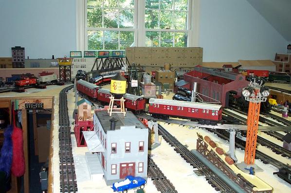
In the process of laying Atlas O track and turnouts. I've read MTH's DCS guide and Barry's book a number of times and it is incredibly helpful for answering questions. But if you don't have an 8x8 layout it seems wiring it anywhere near the ideal protocols is challenging. Curious - how many of you out there have really (really) wired your DCS layouts using star pattern; terminal blocks that are centrally located; only one terminal block per loop (unless you're doing it geographically); only splitting the DCS signal once - from terminal block out to track; only one power drop per track block (even in blocks that contain turnouts), etc. Seriously, just curious how many people out there really wired their layouts per DCS protocols. Or, if not, how DID you wire your DCS layout and does it work without problems? Thanks. Peter
Replies sorted oldest to newest
Yes , I was thinking about that same problem with a large l shaped layout in the basement. Is there a fix?
John
Peter. For the first two layouts, the last of which was 26' by 29' I used common bus wiring with one wire for each loop of track on the + side and one common wire all loops shared on the - side. The lengths of wire were **** near all the same, and we used Atlas O terminal joiners down to the bus wires connected with suitcase connectors. 14 gauge wires for the bus wires. All came back to terminal blocks then to the TIU. I didn't install any insulators, except between loops where we had pairs of switches and no blocks. I had no problems.
Layout three was about 40 something by 26 and I wired it the same way. nothing worked. I spent hours and hours trying to get DCS to work. Finally got it running pretty well on 2 or 3 of the loops but that was it. I did some re wiring to accomplish that.
We are building layout 4 now. It's 60 by 26, and I have two levels of track in - more under construction. We built it exactly as Barry described, except after we consulted him and our friends at the NJ Highrailers, we actually wired it like two Seperate layouts with a common ground, and the trains pass from one layout to the other. Any issues we have had have been my mistakes - we have signal strength of ten basically everywhere. We did add a seperately powered programming track for loading engines into the remotes, and we use that tethered. It works very well.
I wasn't one of the testers, but we installed DCS when it was first available, so I have been running it like ten years, plus or minus. No fooling - Follow Barry's book.
The wire lengths don't have to be equal, so it isn't that hard to star wire. And the terminal block doesn't have to be in the center of the layout. The myth continues! ![]()
I only have 2 wires going to my 12x12 with 2x14 extension layout:
The wires are attached at the top leg of the Wye.
Not a big or complicated layout by any standards, so probably not within your parameters of the poll. I have no signal issues that I'm aware of. No blocks, I do have 2 wires going to the drop-down section of the Wye, but they're hardwired, no On/Off switch.
Attachments
When DCS came out, I had a 14X26 attic layout with 4 loops. Each loop had a bus wire that circled around and ended back at the ZW. Feeder wires were every 4-6 pieces of track. Signal strength was 9-10 throughout.
The new layout is much smaller, 6X16. I decided to use star wiring because it was be easy on a smaller project. The signal strength is 8-10.
Peter
Attachments
No myth.
The reason I want the terminal block at or near the center of the layout is to minimize the longest wire length from the terminal block to the feeder wire.
The main reason that it didn't work in layout three was my power distribution area was in the SE corner and we had very long wire runs in this around the wall layout. The couple of tracks that got better required me to move their terminal block more into the middle, and I isolated the blocks. Isolating the blocks also helps in trouble shooting.
The same length thing. Depends on what you're measuring. No, every pair of wires from the terminal block to the feeder wire don't have to be the same length, but both wires in a single pair need to be pretty close to the same length. The bus in my first two layouts worked because the long loops of wire that made up the bus were the approximately same length; the feeder wires were in the same place; and I used heavy gauge wire.
YMMV.
I rebuilt my layout to make it bigger (25 X 33). In the process, I put star wiring. My distribution feeds are all at one side of my layout, but about midway. My TIUs were below the table. None of my sidings or yard tracks are wired yet.
I had nothing but problems. I have since moved the TIUs above the table and on to the wall. I cut the center rail to have the blocks with each feed. I still had problems with the RF message but it all worked while tethered.
I replaced the batteries on my second remote already having done that on the tethered remote. That worked much better. I am guessing the tethered remote has some type of issue.
Good luck.
I only have 2 wires going to my 12x12...
...Not a big or complicated layout by any standards, so probably not within your parameters of the poll. I have no signal issues that I'm aware of.
Same for me. I don't have an extension like Bob does, but the layout is 12x12 overall. Just two wires and no signal strength problems. Like Bob, my track plan is relatively simple, with a single main line, three long passing sidings, and five spur sidings.
I run DCS, Legacy, and TMCC.
Just my opinion but the ideal block would be about 25 to 30 feet. Whether it's made up of a number of sectional track or 3 foot flex track sections doesn't matter. Sometimes tooo many short blocks will yield a poorer signal over one long one. I also think 150 feet is about max for each channel.
Yep we wire our large super mode layout using Barry's wiring suggestions.However even Barry will tell you, hook up what you think is best and give it a shot.
Here is our shop layout at 21'x10' with only two drops and one isolated track in the yard for troubleshooting and programming.
6 wires (three drops) All 10s
Dave
Attachments
but both wires in a single pair need to be pretty close to the same length.
Actually, no. However, it's smart to do so from a wire management perspective.
Gregg,
Just my opinion but the ideal block would be about 25 to 30 feet. Whether it's made up of a number of sectional track or 3 foot flex track sections
Jim Barrett stated it best: no more than 11-12 track joins. Length of sections doesn't matter.
Sometimes too many short blocks will yield a poorer signal over one long one. I also think 150 feet is about max for each channel.
I agree!
However even Barry will tell you, hook up what you think is best and give it a shot.
Just hook it up and see what's what! ![]()
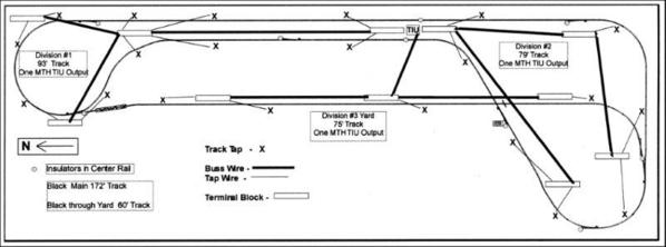
My 24' by 69' Run Room was all purpose wired before the latest Rev L TIU. It's Buss wired with DCS Filters.
This diagram shows wiring for 3 of 16 TIU Outputs. Wire taps to track are made so that every third track is tapped or every track joins a tapped track, which would be after every third joint.
Attachments
I wired it according to the book, no problems
Here is our shop layout at 21'x10' with only two drops and one isolated track in the yard for troubleshooting and programming.
6 wires (three drops) All 10s
Dave
Dave,
To me, that's amazing. I have a small layout with drops all over the place because I have almost as much switch track as non-switch and can't tolerate hesitations and speed variations running conventional.
Looking at your layout if only two drops you must have taken care to insure that there is excellent continuity from one track piece to the next. Is this correct?
Thanks, S
The new layout is much smaller, 6X16. I decided to use star wiring because it was be easy on a smaller project. The signal strength is 8-10.
Peter
Putnam Division,
Not sure where to start here, but it looks like you have Mianne benchwork for your 6'x16' layout. I just talked to Mianne yesterday about the exact same size layout with similar plans (your plan actually looks much nicer than mine).
I am interested in your track plan, the benchwork, the upper shelf (was also thinking about something like that), and it looks like you have another track below the layout also? Would like to see more pictures also, if you have them. Looks like you even have Atlas track, which I am also using.
I don't want to hi-jack this thread, but would like to talk (or would that be type) to you more about your layout and benchwork. Wanted to make sure it was ok with you first, before pestering you, but I could start another thread or email you.
Thanks!
No myth.
The reason I want the terminal block at or near the center of the layout is to minimize the longest wire length from the terminal block to the feeder wire.
The main reason that it didn't work in layout three was my power distribution area was in the SE corner and we had very long wire runs in this around the wall layout. The couple of tracks that got better required me to move their terminal block more into the middle, and I isolated the blocks. Isolating the blocks also helps in trouble shooting.
Mr. Muff
Very good idea, but it doesn't have to be dead center of the layout is what I'm trying to get across.
But the reason for your improvement can be many reasons. Including being near the DCS limit of a channel and by using shorter runs of wires brings the channel within its limits. I don't think the signal can distinguish track from wiring, so more of either can place the channel at its limit.
We pretty much followed the star pattern on the wiring as much as possible. In some instances we did wire out from one block to another "signal splitter" block without any problems which related to that pattern.
First - thanks to everyone who got involved in this poll! It sounds like most people just wire without much thought to the MTH recommendations and it usually works just fine. This is great news as I'll explain below under "the reason."
rtr12 - the reason is because the protocols in both MTH's guide and Barry's book are ideals and, as a practical matter, very, very difficult to follow implement to the "T" if your layout isn't a square or if you are using Atlas O turnouts and don’t want to re-wire them. This isn’t anything provocative – Barry basically tells you in his book that he is providing “ideal” protocols. Regarding those who say they've wired per MTH / Barry protocols – with respect, I’ve almost always found that when I ask, it turns out they have not. Yes, many star pattern wire. But things often get hazy when you ask if terminal blocks are equidistant from all power drop points, if the block protocols are followed and whether they truly use one drop per block, even in blocks with Atlas O turnouts. Etc. Again, nothing wrong with any of this. Just wanted an accurate read on what people actually do and whether it works.
The reason:
My 10-year old sons and I are in the process of building our first "real" layout. An exciting experience, to be sure. It's 33 x 15, will have 2 main lines, an inter-connecting mountain line and a discrete Elevated line. Using Atlas O track and turnouts. It will have a small yard and a couple of very long staging tracks that I’d like to toggle on/off. I’m getting to the point, however, of paralysis in trying to figure out how to wire the layout with confidence, given it can’t be done in strict accordance with MTH protocols.
Regardless of so-called “myths,” from memory, Barry’s book suggests placing terminal blocks “centrally.” As a practical matter, that amounts to wires runs of almost the same length. AndBarry's book also says to use one power drop per track block. Finally, I believe Barry states that there should be one and only one terminal block for each TIU output, and not to jumper between terminal blocks (why, I’m not sure – for instance, what do you do if you need more than 24 drops for a given loop?).
In any event, we were first thinking a single centrally located panel with my TIU and then have the terminal blocks on that same panel and run wires from there. Given the layout dimensions, we can’t possibly have the terminal blocks equidistant from all terminal points no matter where I place them, so why not just place them on the panel, where they are easily accessed?
Then we were thinking about a three panel approach. A center panel and two satellite panels (one satellite on each end of the layout). TIU power for each TIU output would go to a specific terminal block on the center panel (one for each loop). And then a 12/14 AWG wire would run from each of those terminal blocks to a designated satellite panel terminal block (again, respective to the same loop). Would star pattern wire from each panel to respective loop track blocks in that sector, making wire runs short and neat. The problem: as mentioned above, doing it this way would violate the protocols in Barry’s book. We would be splitting the signal more than once and we would, in essence, be using 3 terminal blocks per TIU output. Since this is our first time, there’s a lot of analysis here due to not having the ability to rely on past experiences (and wanting to get it right).
Thanks again for the inputs!
Peter
Peter,
for instance, what do you do if you need more than 24 drops for a given loop?).
You would use more than 1 TIU channel for the loop
I wouldn't go against the norm. I wired my layout and then tuned it in. As I added sidings and more track that is. I use to run it all on one channel just to show it could be done, and because it worked with my G gauge on the second channel with my two bricks at that time.
I have since gone to three channels for my O gauge alone. I will probably add at least one more channel with the new layout, maybe more.
I haven't found any good reason with keeping certain wire lengths or even lengths. I have a three foot drop and a fifty. Maybe I'm getting away with something there?
I'd like my tiu moved to the center. That was not possible and would have required more tiu's. I didn't have the money. So I made due with what I had and it worked.
I go by this self motto, try and follow the rules. Apply them to each problem to work out a solution. If it works, don't touch it!, don't question why, just run with it. If it doesn't work step back and think it thru, there's probably something done wrong that is causing the problem. Each of the guys that used to be active here, helped form solutions that I learned from. Barry put them in writing. I bought the book! It's not a bible. It's a practical reference that works. Try not to fight the force!!!
I put all the gear (TIUs, TMCC, etc) under the layout about the center ... and then installed a 6-track yard over it before I knew better ...
Good reception however for some reason. Maybe it's because they are mounted vertically on a plywood sheet 2 feet off the floor with no line-of-sight obstructions?
What does seem to make a difference is when the batteries in the controllers get weak, but not enough to set off the low battery icon. Putting in new batteries fixes it.
Maybe just dumb luck most of it works most of the time so far is probably more like it
![]()
PJB,
Looks like you have put a lot more into studying this than I have. What I meant was for anyone having Barry's book or MTH's manual. In that case I don't see why anyone planning or wiring a layout for DCS would not follow Barry's or MTH's recommended wiring methods and knowingly do it differently?
I'm sure those methods in the books are ideal, but I think Barry even says that as you point out. I think he also says to wire as close as you can to the rules that is practical or can be done in you layout or something to that effect. I have not been readin the book for a while. I may get back to it after this reading thread.
I will try to explain what I am planning to do. Maybe I have some things wrong, or even everything? Don't know for sure, but if I do I hope you or someone else will let me know where my plan is flawed so I can correct it. Learned a long time ago that no one knows everything and I am always willing to learn from others.
Your layout is much larger than mine to start with, but I want to eventually add on as I can in the future (funds permitting). Starting with a 6'x16' rectangle, I hope to add another 6'x24' L off of one end and then from that a 3'x12-14' yard in kind of a U from the 6'x24' run. I will be following Barry's advice, as I interpret it, as close as I can all the way. I too want to minimize problems and have DCS and Legacy is on order.
I don't know what your layout will look like, but as far as equidistant terminal blocks, you could just put them anywhere that is convenient. Measure to the furthest one and make all the wires to feed the terminal blocks that length. Roll up what is not used at the ends or something. I am using OGR's #14 wire for that, which is paired. (Just a passing thought here, to ease your equidistant thoughts, not really suggesting you do it this way. Sorry if it was misunderstood) (The thought has gotten some clarifications below, should clear this up now)
As far as the drops to the blocks, I read those to be 1 power and 1 common, both being the same length (for the pair) from terminal block to track. Again I am using OGR's wire which is paired. I think 24 blocks would be a lot of track, not sure I will have anything close to being that large? I have only purchased the smaller 12 terminal MTH blocks.
For the sidings and spurs I am using relays located at the individual power feeds to the siding or spur. A smaller gauge wire will be run from the toggle switch at the control panel to activate the relay.
I am also using Atlas-O track and switches and at least some will have the #6924 non-derail boards. I am still planning their location and wiring. Was planning to isolate the switch parts as required and either feed power to them with jumpers or as a block. I'm still fiddling with these on the bench and haven't done anything with them for the last few weeks (need to get going again). What ever I end up with I will be trying to follow the wiring guidelines.
I have not decided on the use of an AIU for switching, may do some that way and leave some manual, or just all manual? I will be getting an AIU to use for some lighting and other accessories.
I am fairly new to this as well and this will also be my first permanent layout, and also probably my last. So, like you, I want to get it right and have as few problems as possible. I definitely don't want to make any deliberate mistakes.
My intent is not to promote any bad advice, just explain my interpretation of what I am trying to do and hope it will all work. If I have gotten anything wrong here I hope someone will correct it.
I don't know what your layout will look like, but as far as equidistant terminal blocks, you could just put them anywhere that is convenient. Measure to the furthest one and make all the wires to feed the terminal blocks that length. Roll up what is not used at the ends or something. I am using OGR's #14 wire for that, which is paired.
I don't think you'll find anything about having to roll up wire to make the wires equal in Barry's book.![]()
Joe,
I don't think you'll find anything about having to roll up wire to make the wires equal in Barry's book.
Correct. That is not a requirement or even a "nice to do".
My layout has Star wiring true to Barry's instructions. Signal quality readings are tens everywhere on well over 300 feet of track, 14 switches and many sidings.
I don't know what your layout will look like, but as far as equidistant terminal blocks, you could just put them anywhere that is convenient. Measure to the furthest one and make all the wires to feed the terminal blocks that length. Roll up what is not used at the ends or something. I am using OGR's #14 wire for that, which is paired.
I don't think you'll find anything about having to roll up wire to make the wires equal in Barry's book.![]()
Nor would I expect to. Just a passing thought which I thought was indicated by the or something at the end. The post I was replying to mentioned a concern for placing terminal blocks and wire lengths of equal distances a couple of times. I won't be doing that. Maybe I should edit that a bit. Maybe I missed the idea of the post?
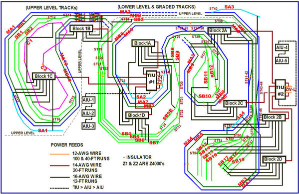
Star wiring, and although I tried to keep the 14AWG wires from the TIU to the terminal blocks (actually, relay modules) about the same length as the others, and also the 16AWG wires from the terminal blocks or relay modules to the tracks about the same length as each other, I was not very successful. Some ended up being 1-1/2 times to 2x as long as the others.
Nevertheless, the system works fine and the trains run without any significant problem.
I have added a couple of spurs since I drew this diagram, but it reflects the basic wiring.
Alex
Attachments
Peter,
for instance, what do you do if you need more than 24 drops for a given loop?).
You would use more than 1 TIU channel for the loop
Hi Barry,
Aren't you glad you wrote the book? You're guaranteed to have your name pop up on this forum at least every day! (seriously, thanks for always jumping in to help.)
When you say "use more than 1 TIU channel" if one needs more than 24 ports on a terminal block (not that I do, but curious here as to why), presumably, what you're saying is that greater than 24 splits could result in too much signal degradation?
Peter
Peter,
what you're saying is that greater than 24 splits could result in too much signal degradation?
That's my intent.
Prior to the Rev. L's availability, I found that, on my layout, once I split a TIU channel more than 14 ways, I saw serious signal degradation.
However, with the Rev. L's installed, that "limit" seems to have moved above 14. I suspect that somewhere above 24 splits with a Rev. L channel, we might see issues again.
Gentlemen,
Alex is absolutley correct, using Jims 12 track method works great even with the
length of the wiring being run in different lengths, the key engineerly seems to be the number of joins, I also used the magic lights thru out my multi level L shaped layout, and ran with all 10's. Using the long sections of FasTrack helped greatly on my DCS layout, no signal loss at all, even with the long sections multipuled. The other thing I advise is always test as you build your layout, having a couple bad sections of track with a DCS layout can definitely mess things up, this is especially true for switches, test every switch before inserting them in your DCS layout.
PCRR/Dave


