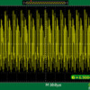
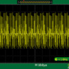
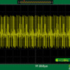
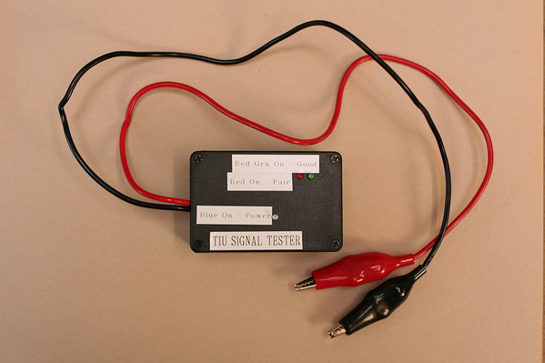
I mentioned this before, but it needs to be stated again.  This little tester ONLY works properly with a pure sine wave transformer feeding the TIU!  I tried to use the Z1000 with the controller, and the red light is always on.  When I look at the signal on the 'scope, it's obvious why, there is a big zit on the waveform that it triggering the 123.

Use a pure sinewave transformer, and you'll get the results you're looking for!

Hi Guys.....

I'm a little unclear as to what the steps are for calibrating and using the TIU Tester. So, I took the comments and tried to consolidate them into a single document for calibrating and using the TIU Tester.

Would you please review and let me know if any of this not correct? I would be happy to update it and repost for anyone who wants to use it. This is what I came up with based on my understanding of the steps mentioned in the various posts:

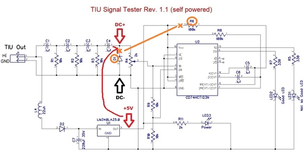
1. Jumper the circuit board from +5v side to the DC+ side.
2. Apply 18 volts AC (using a full sine wave transformer (e.g. old Lionel transformer); NOT a modified or "chopped" sine wave transformer (e.g. MTH Z4000 transformer)) to the TIU Tester posts on the circuit board.
3. The "power" (Blue) LED should illuminate.
4. Adjusting the trip pot:
    A. Start by turning and setting the trim pot fully in one direction to cause both the Red and Green
        LEDs to flash.
    B. Then turn the trim pot in the opposite direction (from above) to cause both the Red and Green
         LEDs to not flash at all.
    C. Finally, turn the trim pot from the point where the Red and Green LEDs are not flashing to the point
         where only ONE LED is flashing (not sure if it matters which LED should be flashing?).
     D. This procedure sets the tester (calibrates it) to detect a minimum 10 volt DCS "command" signal.
5. Remove the circuit board jumper.
6. Apply power to a TIU.
7. Before testing a TIU, set the TIU's Variable ports to "Fixed".
8. Connect the Tester's TIU output posts to one of the TIU channel outputs to be tested (does it matter which Tester post is connected to which TIU channel out; i.e. Red or Black?).
9. Press one of the "command" buttons on the TIU's remote (Whistle, Startup, Bell, etc.) to send a DCS signal.
10. Monitor the Red/Green LEDs on the Tester. When both LEDs flash, the TIU is sending out a DCS signal that's 10 volts or more. This indicates the TIU channel being tested is not damaged and is functioning as it should be. Anything else indicates the TIU channel may be damaged and in need of repair.

I'm not sure of the significance of the Red and Green LEDS. A lone Red LED flashing is a 5 volt or less DCS command signal? I don't know if a lone Green LEDflashing will ever occur?

Thanks!

Last edited by Junior
Junior posted:

Thanks GRJ....I will add that note. Any thoughts on the other bolded questions I had?

The Hi post on the TIU connection is the red post, yes it does matter.

For the LED's flashing, if only one is flashing, it has to be the red one, the green one only flashes when there's more amplitude, and by definition, the red one is already flashing.

The applied AC voltage to the TIU is non-critical, my 1033 applies 16 volts maximum, works just fine.  The AC voltage is really just to power the TIU and the test board, probably 12 VAC would do that just fine.  The key requirement is a pure sine wave so you don't get noise artifacts through the filter to give false triggering.


gunrunnerjohn posted:

I haven't tried the Z4000, mine is packed up and on the bottom of a pile of boxes.

Adrian, wouldn't going as low as 100 ohms stomp on our signal a bit too much?

0.1uF X 100 ohm is still a 100KHz cutoff well below the 0.7 to 5MHz DCS power spectral density. Should work ok I think.


I can’t check it right now though because I’m still trapped in nowheresville USA defending the NASA spacecraft from scorpions and coral snakes with a pointy stick ...

Junior posted:


1. Jumper the circuit board from +5v side to the DC+ side.


4. Adjusting the trip pot:
    A. Start by turning and setting the trim pot fully in one direction to cause both the Red and Green LEDs to flash when +5V is momentarily connected to DC+.
    B. Then turn the trim pot in the opposite direction (from above) to cause both the Red and Green LEDs to not flash at all when +5V is momentarily connected to DC+.
    C. Finally, turn the trim pot from the point where the Red and Green LEDs are not flashing to the point  where only the Red LED is flashing  when +5V is momentarily connected to DC+.
     D. This procedure sets the tester (calibrates it) to detect a minimum 10 volt DCS "command" signal.


5. Remove the circuit board jumper.


It's a momentary connection between +5V and DC+ which should cause 0,1, or 2 LEDs to briefly flash.  If 1 LED flashes, it well be the Red one.

Note above that engineer-joe is considering a momentary push-button switch to make this connection between +5V and DC+ to facilitate calibration.  I had earlier suggested an alligator jumper cable - one side clipped to one side, and then the other side momentarily touched to the other side.

I found time tonight to assemble the kit.  I want to thank GRJ for designing the board in his usual excellent manner, and rtr12 for compiling the kit.  Having color distinction problems, I really appreciated rtr12 marking the sets of resistors with their values.  Saved me the problem of either asking Mrs RJR to tell me the colors, or pulling out my trusty Fluke.

Up in this thread is a picture of a board on which the author had superimposed indication of where the flat sides and white stripes go.  Very helpful.

I plugged it into a Rev L Fixed circuit without calibrating, and fired up the layout.  The red came on whenever I sent a signal, and the green rarely.  What puzzled me is that when trains were running, both green & red would flicker periodically.

Now to read back through this thread to study calibration & operation.

As an aside, I have an occasional doubletoot problem with softkeys.  I notice there was no flash before the second toot.  After closing down, occurred to me that I can put it on the other TIU and see if there is crosstalk causing the 2nd TIU to also issue a signal.

GRJ & RTR12: Hope you guys produce more useful kits.

Last edited by RJR
RJR posted:

...I plugged it into a Rev L Fixed circuit without calibrating, and fired up the layout.  The red came on whenever I sent a signal, and the green rarely.  What puzzled me is that when trains were running, both green & red would flicker periodically.

Apparently you're attached to a powered layout with engine(s).  This is not the intended application of the simple tester.  The DCS signal voltage at the TIU output drops as soon as you load it with your layout and engine(s).  The simple tester is meant to measure the DCS signal level with nothing loading the TIU output.

Both LEDs a re flickering with running trains because of occasional transients typically from dirty track or momentary loss of roller-to-track contact.  These transients are typically 30 Volts or more and hence large enough to trigger the simple tester.


I have a REV H I use for Test bench testing.  It had the same calibrated output (FIX1 and 2 only) as my REV L.  It is an old damaged TIU (Bad VAR1 and 2) but it had strong output on F1/2.  If you go to my test result post, you will see that how the TIU is powered (F1 or Aux Port) matters on how the LED respond.

If the TIU is only powered by F1 at startup of the tester, the LED Stay solid for a period.  This lead me to think a strong DC Signal is present.  So I measured this with a basic VM, and at TIU start up I got a 50-60mvdc output that would go down after the LED started to flash.  This was repeatable on all channels, even tried the rev H which read at the higher end.

So next bad TIU I get I am going to see if this DC Signal at startup can also be used for a basic correlation of signal strength.   G

RJR posted:

Question, would calibrating the unit on a Rev G or Rev H, which apparently didn't suffer from signal degradation, be satisfactory for use on a Rev L?

It makes no difference, the DCS signal is the DCS signal.  However, as George says, if the older TIU doesn't have full signal strength, that could be a problem, you don't know what results the calibration gets.

Thanks RJR, you are very kind. But without Adrian, GRJ, Stan and anyone else that helps with the designs of these things I would not be able to put any kits together on my own. These guys need the big thanks, they are the idea and circuit design folks doing all the heavy brain work. I am quite thankful for them as well.

I will admit the kits are kind of fun to put together and send out, and good experience too. Learn something every day! Plus they are educating me on much better shipping methods as well. Maybe an old dog can still learn a new trick or two? 

I know GRJ, having met him at a few Yorks.  Never met Stan and Adrian, but they, like GRJ, have always shown themselves to be true gentlemen on the forum, always ready to lend their deep knowledge to someone floundering.

I recall a few years ago when I was designing a system to use light rather than track shoes to activate operating cars, Stan provided invaluable help.

Dave, I said that half in jest.  I have no idea what those little surges would do to the tester (if anything) and I don't intend to try to find out.

I do see this device as having the potential to ascertain the source of doubletoot.  I noticed that no signal went out from my TIU when the second toot occurred.  Haven't had a chance to see what happens on the other TIU.  This does require a loco to be powered up.

With help, suggestions and even an example I thought maybe something should be included with these kits that might help with assembly. I'm including this with each kit now. For the ones that already have their kits (and for all), I thought I would post it here. (Probably too late for some.) It is really just the info already here in this thread, but now some of it is all in one place. 

Attachments

For those that don't have an oscilloscope, here's a video showing the calibration method I suggested earlier using the on-board 5V DC voltage as a reference level:

As it turns out, you can simply short the wire-leads from two adjacent components (D1 and R6).  Or as engineer-joe suggested, you could attach a momentary SPST push-button switch to these points if the circuit is mounted in a box whereby you don't have access. 

DC%2520trigger%2520calibration

Note I added a drop of white paint to the trim-pot to better show the adjustment angle.

This sets the threshold to about 10V.  You can then further refine/trim the threshold to a known-good TIU output.  Note that turning the trim-pot CW increases the threshold.  The idea is without a starting point (10V in this case), you don't know if your "known-good" TIU output is at the desired 12V (or whatever) signal level.  As Adrian previously reported, you can get all 10's on the DCS signal test with a signal level of less than 5V; but a TIU port that only puts out 5V is probably damaged.

Again, thanks to rtr12 for putting together these kits!  

gold star small

Attachments

Images (2)
  • DC%2520trigger%2520calibration
  • gold star small
Last edited by stan2004

Aha.  I see how it can be confusing.   The "red wire" is meant to be a momentary connection.  Each time you make the connection, it generates one +5V trigger pulse.

My observation after looking at the actual board is that you can make this same momentary connection by shorting (using a metal screwdriver tip in the video) two adjacent components.  The "orange line" in the schematic shows this momentary connection.  Again, each time you make the connection, it generates one +5V trigger pulse.  It is just happen-stance (dumb luck?) that the board was configured in this way such that you don't need to add a temporary wire for calibration.

Not sure if I'm being clear 

Stan, Thanks so much for the calibration update and video. That really helps things for calibration and makes it easier as well. And you are most welcome. I've actually been enjoying putting the kits together. But it wouldn't be possible without Adrian, GRJ and your help with calibration. (I'll still take the gold star though, but I'd be happy to share. )

Last edited by rtr12

Dave, I think Stan is saying that we don't need to pay attention to the arrows anymore, just follow his calibration video and all should be well. I believe the only wires in his video are going to the TIU output to power the tester at it's power inputs.

Edit: The arrows in Stan's mark up schematic would still tell you that 5vdc was present, but I believe the blue light does the same thing. 

Maybe Stan will clarify this, or add to it, he words things much better than I do and he knows for certain what's happening too!

Edit again: Sorry Stan, I didn't see your post above? I must have been posting at the same time you were?

Last edited by rtr12

I tried Stan's calibration method, but I wasn't totally happy with the outcome, so I dropped back to my 'scope method.

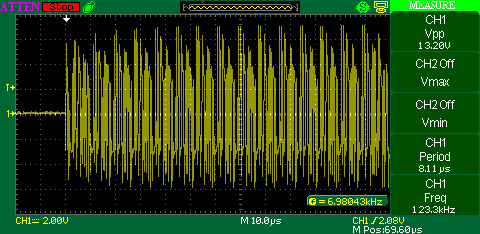
I start out with a good signal and make sure both LED's are blinking.  This signal is measured with a separate hi-pass filter right off the output of the TIU.

TIU Full Voltage Output

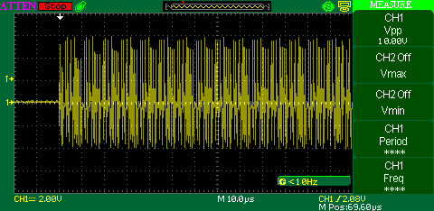
Next, I put 3.3uf of capacitance across the TIU output pins and fire off another command.  In this case, I "tune" for just a couple winks of the green LED, most of the time it's off.  I consider this signal marginal.

TIU Attenuated Output 10V

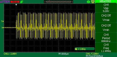
Finally, I put 5.0uf of capacitance across the TIU outputs and make sure I never see the green LED.  At this voltage, I figure the TIU has lost at least one of the ACT244 gates.

TIU Attenuated Output 9.28V

I then marked the pot and support with a marker line so it can be returned to this setting without a total calibration again.

Attachments

Images (3)
  • TIU Full Voltage Output
  • TIU Attenuated Output 10V
  • TIU Attenuated Output 9.28V
stan2004 posted:

For those that don't have an oscilloscope, here's a video showing the calibration method I suggested earlier using the on-board 5V DC voltage as a reference level:

As it turns out, you can simply short the wire-leads from two adjacent components (D1 and R6).  Or as engineer-joe suggested, you could attach a momentary SPST push-button switch to these points if the circuit is mounted in a box whereby you don't have access. 

DC%2520trigger%2520calibration

Note I added a drop of white paint to the trim-pot to better show the adjustment angle.

This sets the threshold to about 10V.  You can then further refine/trim the threshold to a known-good TIU output.  Note that turning the trim-pot CW increases the threshold.  The idea is without a starting point (10V in this case), you don't know if your "known-good" TIU output is at the desired 12V (or whatever) signal level.  As Adrian previously reported, you can get all 10's on the DCS signal test with a signal level of less than 5V; but a TIU port that only puts out 5V is probably damaged.

Again, thanks to rtr12 for putting together these kits!  

gold star small

Dahhhhhhhhhhhh…… I did good? 

I still haven't actually used or even calibrated my device fully again. I'm doing other things and I'll get back to this when I have the extra patience. I got frustrated that my outdoor RR keeps going south. I'm guessing that it's a wiring issue that the ends are degrading. Maybe the TIU is weak? I haven't started full trouble shooting. I feel that this device will help me in the coming years to save some time.

I thought having a switch built inside my device's project box would help me calibrate it. Knowing that Stan posted calibration should last, I could have done it better before mounting it permanently. I had my O scale layout connected to the TIU's output so I don't know if the unit was calibrated correctly.

stan2004 posted:
rtr12 posted:

...I am going to ask Stan if he minds me including his instructions and his picture showing component orientation in with the parts list.

Anything you think would help is fine by me.

swise posted:

… "AC Track voltage" means hook 18VAC up to the test board?

Yup.


Stan, when you did your Calibration Video what power did you connect the tester to?

While calibrating with your video my tester was connected to an 18V AC TIU output.  Was that correct?  I'm getting all reds or nothing on my outputs.  My blue Power LED works fine.

Correct.  Apply 18V AC TIU output.  The 18V AC should be from a train transformer - not the chopped-sinewave variable output from a conventional controller.

Not sure what you mean by "all reds".  There should be one red and one green LED.  If you are hooking up to a TIU output that has just been powered you may get some LED flashing as the TIU channel sprays the watchdog DCS packet for tens of seconds.  But after this initial activity, the red and green LED should be OFF.  Or, for calibration purposes, it might be simpler to just hook the tester to 18V AC (without the TIU present).

With board powered (blue LED on), referring to 9/21 video:

- rotate trimpot full CCW.  Tap (bridge/short together) the two indicated points on the board using a metal screwdriver.  Both LEDs should flash on each tap.

- rotate trimpot full CW.  Tap the two indicated points.  Neither LED should flash.

- if you don't get above two behaviors, then there's a troubleshooting issue - something is not right.

- otherwise back off the trimpot from full CW to the point where just the red LED starts flashing on each tap.


Thank you, Stan.  I re-calibrated with 18 v from postwar ZW.  (with about the same results).

While testing a new Rev L TIU, all 4 OUPUTS (1 at a time) Blue On and at the same time the Blu and Red fast blip once and go off.  Does that mean very good signal or NO signal?

I posted test results toward the bottom of this topic, Post for Use and Interpretation of TIU Tester Results, for 4 TIUs.  I didn't get any green red combination results, just red.  I'm puzzled why I don't see any red green combos.


Last edited by Susan Deats

Susan,

To properly use the tool:

   Turn on speed Mode in the remote.

   Do not have an engine on the track.

   Connect the test tool to a TIU channel.

   Put power to a track on the TIU’s channel.

   Start up an engine in the Active Engine List (that isn’t on the tracks).

Send commands.

Monitor the tool’s responses.

stan2004 posted:

Correct.  Apply 18V AC TIU output.  The 18V AC should be from a train transformer - not the chopped-sinewave variable output from a conventional controller.

Not sure what you mean by "all reds".  There should be one red and one green LED.  If you are hooking up to a TIU output that has just been powered you may get some LED flashing as the TIU channel sprays the watchdog DCS packet for tens of seconds.  But after this initial activity, the red and green LED should be OFF.  Or, for calibration purposes, it might be simpler to just hook the tester to 18V AC (without the TIU present).

With board powered (blue LED on), referring to 9/21 video:

- rotate trimpot full CCW.  Tap (bridge/short together) the two indicated points on the board using a metal screwdriver.  Both LEDs should flash on each tap.

- rotate trimpot full CW.  Tap the two indicated points.  Neither LED should flash.

- if you don't get above two behaviors, then there's a troubleshooting issue - something is not right.

- otherwise back off the trimpot from full CW to the point where just the red LED starts flashing on each tap.


My tester required me to back off the trimpot a bit more until the red and green LEDs did 2 long flashes when testing my best TIU output (sometimes I cheat).

Now I have red with green for very good and red for okay.  I will retest all five TIUs to verify.  My newest TIU has absolutely no signal outputs and I have a Return Authorization from MTH.  It also has the tiny TVSs.

gunrunnerjohn posted:

Perhaps, I tested a known good TIU (checked with my 'scope), and the variable channels (in fixed mode) tested just the same as the fixed channels.

Here's a test of the board using the Lionel 1033 to power the TIU, tester is connected to Variable #1 (in fixed voltage mode) to illustrate the variable channels work the same as the fixed channels.

During your tests, with your tester connected to the TIU variable output, what was your Remote "talking" to when you activated the whistle and bell?

Susan, the remote is only talking to the TIU.  The tester should be used with ONLY the TIU connected, no track, no engines, etc.  Also, you need a pure sine wave transformer to power the TIU as the sawtooth from most electronic transformers will screw things up.

I put the remote into SPEED mode so that it doesn't stall waiting on the engine when I press keys.

gunrunnerjohn posted:

Susan, the remote is only talking to the TIU.  The tester should be used with ONLY the TIU connected, no track, no engines, etc.  Also, you need a pure sine wave transformer to power the TIU as the sawtooth from most electronic transformers will screw things up.

I put the remote into SPEED mode so that it doesn't stall waiting on the engine when I press keys.

What engine?  When I bench tested I connected the tester to the Output and just tested for the watchdog signal.

I have an engine loaded, it can be any engine.  If you're in SPEED mode, you can do stuff like STARTUP (does a nice long string), WHISTLE, BELL, etc.  You are addressing the engine, but since there's no track or engines connected, obviously it doesn't answer.  We're just looking at the outgoing signal strength here.

Didn't you see my video of my testing?  This shows you what I'm doing.  The extra board on the output of the TIU is my filter for the 'scope, it doesn't affect what the test board is seeing.  This test was on variable #1 in fixed mode with a 1033 transformer powering the TIU.  Note that the transformer voltage isn't significant as long as it's enough for the TIU to run, it can be anything from around 12 volts and up.

Last edited by gunrunnerjohn

This TIU Tester is the best thing that's happened this year.  When I decided to install the DCS Wifi capability to all tracks with new TIUs with the USB ports, a series of gremlins appeared that would have precipitated the implosion of my Run Room.  Fortunately with all the TIU signal discussion in the forum topic, "Weak DCS signals, Failed TIU Output Drivers, and Design Solutions developed under collaboration between AGHR and MTH", and the TIU Signal Tester Design I have reached the stage where I can make do with what I have until I can improve my TIUs.

I am also looking forward to playing trains with my tablet and "quilling" whistles.

A pdf of my novice Tester Build is attached.

TesterComplete

Attachments

Images (1)
  • TesterComplete
Files (1)
Last edited by Susan Deats

Cool, I'm glad that I was a small part of bringing this to the masses.  Adrian probably deserves a major part of the credit, and of course Stan for suggesting the multi-level aspect of the design.  And we can't forget Tom for coming up with the great and detailed instruction set and parts set.

I like your little box, makes a nice unit and it won't get knocked around.

Susan Deats posted:

This TIU Tester is the best thing that's happened this year.  When I decided to install the DCS Wifi capability to all tracks with new TIUs with the USB ports, a series of gremlins appeared that would have precipitated the implosion of my Run Room.  Fortunately with all the TIU signal discussion in the forum topic, "Weak DCS signals, Failed TIU Output Drivers, and Design Solutions developed under collaboration between AGHR and MTH", and the TIU Signal Tester Design I have reached the stage where I can make do with what I have until I can improve my TIUs.

I am also looking forward to playing trains with my tablet and "quilling" whistles.

A pdf of my novice Tester Build is attached.


I'm glad it was helpful. When everyone jumps in to help and refine the design, neat stuff comes out!

Those are very nice instructions Susan. Glad you got everything up and going and it sounds like trains are running again, the best part! Along with GRJ, I like the box you installed it in as well. I might try that myself, I have a few old Radio Shack boxes around here somewhere.

And as Adrian (who got this going) said above, "When everyone jumps in to help and refine the design, neat stuff comes out!" GRJ and Stan refined everything to make it what it is today, then GRJ did the PCB designs and layouts. And I think it has been a great learning thread as well. Although I can't always keep up, I really enjoy following these folks when they are preparing to make the "neat stuff come out"! 

I am honored to have been allowed by these folks to act as 'ordering and shipping clerk', which I do find to be enjoyable (they helped me with that too!). Makes me feel like I am contributing here in some small way.

Also, for everyone else here on the forum or elsewhere, I plan to keep the kits available for anyone that wants one.  

I ordered a kit from Tom and just finished putting it together. Calibrated it with the "shorting screwdriver method" and it appears to be working correctly. First I ran a couple of engines on the layout to check signal strength and pretty much got 10's all around. Then I checked each TIU channel with the checker, first with the TIU hooked to the layout and then with the TIU disconnected from the layout. In all cases the green light flashed, never got the red light to flash.

So is this telling me my signal strength is somewhere between 5 and 10 volts? I understand calibrating the tester with a known good TIU so the pot can be adjusted to just make both leds flash, but how do you know if you have a "good" TIU? Will a new, just out of the box TIU always have a 10 to 12 volt signal? Is there any other way to calibrate it to 10 volts?

I would also like to thank Adrian, Gunrunner, and Tom for researching, designing, and putting the tester kits together.

Ken

kanawha posted:

... In all cases the green light flashed, never got the red light to flash.

When you say "the green light flashed," you do mean both green & red simultaneously?  You should never be able to make JUST the green light to flash (by itself).

OTOH, if the signal is in the "maybe" zone (5-10V) then you can get JUST the red to flash.

There is no published info from MTH that specifies the minimum DCS signal level fresh out of the box.  Anecdotally, based on Adrian's extensive study (refer to other OGR threads where he shows tables, oscilloscope photos, etc.), new TIUs indeed put out more than 10V.  So, in practice, if you have a "known good" TIU and adjust the trimpot to flash green (and red) when there is DCS activity, then you will be setting the threshold higher than 10V.  My guess is the change in trimpot "angle" between 10V and, say, 12V will be small...maybe only 10-20 degrees?

Remember, the screw-driver calibration technique is just to get you a seat at the table - no oscilloscope required.

GGG posted:

Did you put the green LED in the wrong spot?  Testing TIU while still attached to the layout or even a test track with lighted lockon will effect results.  Test TIU stand alone.  G

GGG and STAN2004,

I installed the LED's in the correct place, the problem is when I wrote the post I meant to say the red light flashed and the green light wouldn't flash. My bad!

After re-reading all the posts I decided to calibrate the tester to my home layout TIU. I have one Variable channel that I never have used so I assumed that channel was good. Set that channel to fixed and re-caled  the tester so both LED's flash when sending a command. Interestingly I only had to turn the pot about 10 deg CCW from its previous position. Checked the other three channels (unhooked from layout) and everything tested good.

Now to check our club's TIU's which we have been having a number of problems with.

Ken

Back on page 6 of this thread, RTR12 mentions ordering them at DigiKey but I didn't see an actual part #.  With the Jan 2019 price hike by USPS, the minimum DigiKey shipping charge for First Class Mail is now over $4.

As mentioned in the post above his, I get them for about a dime a piece on eBay (free shipping from Asia).  Search eBay for "2.54mm screw terminal 2 poles"

Untitled

Attachments

Images (1)
  • Untitled
gunrunnerjohn posted:
stan2004 posted:

Tough crowd you guys are.  OK, for anyone who feels misled, I will send you 11 cents in the mail.  However, you must pay postage.   

Stan, I was going to buy 1,000, so I'll need $11.00, and I'll pay the postage.

Not so fast!  Note that the eBay listing says "OR BEST OFFER".  Does that mean if seller accepts an offer of $99 (instead of $111) for 1,000 pieces that you will SEND ME a $1? 

But a promise is a promise.  I will send you 11 cents for each of your 100 transactions.  That's 11 cents x 100 = 1,100 cents.   A penny weighs 0.088 ounces.  So package will weigh 7 pounds.  To save you postage I'll use a Priority Mail Flat Rate box.  I don't think I can fit 22 rolls pennies in a Small Flat Rate Box so I'd need to use a Medium Flat Rate box.  That's $14.35.

You know my Paypal address so as soon as I see a payment of $14.35 from you I'll send you 1100 cents. 


RJR posted:

RTR12.  Do you have a catalog number or location for the tiny 2-pole connector you used on these kits?

Digikey part # ED10561-ND, but it's way more than Stan's TBs. I tried a couple others (Digkey) for a little less, but these seemed better to me, wire size, screws, quality, etc. (Long story, but I tried some from ebay as well and that hasn't yet worked out, for me anyway. First time I have really ever had problems ordering parts from Asia on ebay too.)

It's also on the parts list included with the tester as: TB1 Term Block OSTVN02A150 On Shore Technology 2.54MM 2POS PCB ED10561-ND

----------------------------------------------------------------------------------------

A bit of a kit update (for anyone interested) on the kits, since it was mentioned earlier:

Digikey has also added tariff charges to most of the parts used for the TIU Tester, I haven't checked all of them. And as mentioned the postage has increased a little too. I still have enough parts left for maybe 10-12 complete kits at the pre-tariff prices.

---------------------------------------------------------------------------------------

Lastly... Oh-my, the crowd has gotten tougher during my absence here...  (or, I always enjoy GRJ & Stan's back and forth )

Last edited by rtr12
rad400 posted:

GRJ , RTR12

If you still have any more kits of the port tester, I will take one.  I already put one together for the club, but like to have one for home use/testing.

Let me know.

Thanks,

Bob D

FredB posted:

Hi RTR12

If you still have these test kits available I would like two, one for the club and one for my home layout . Payment through PayPal is not a problem. Thanks 

Fred B

MTH ASC

TCA MEMBER 16-71895

Bob & Fred,

Yes, I still have some kits left. Could you please email your requests to me at the email address in my profile?

I can keep track of the emails, but I seem to lose things here on the forum.

Thanks,

Tom (rtr12)

Last edited by rtr12

Add Reply

Post
The DCS Forum is sponsored by

OGR Publishing, Inc., 1310 Eastside Centre Ct, Suite 6, Mountain Home, AR 72653
800-980-OGRR (6477)
www.ogaugerr.com

×
×
×
×
Link copied to your clipboard.
×
×