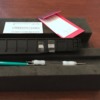
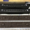
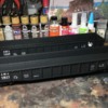
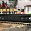
I've been sitting on a couple "old" Atlas undecorated 52'6" gondola kits for a year or so and finally found the motivation (and time!!) over the past couple weeks to assemble, detail, paint and letter them. I took pictures with my iPhone throughout the build process and rather than just filing them away in my digital photo library, I figured I'd share them--along with a verbal description of each step--here on the Forum. Sort of a "How-to" or "How I did it" thread for anyone interested.
Project Background:
As my Forum screen name indicates, I'm a big fan of the Jersey Central Railroad (CNJ). The CNJ had a large group of 52'6" gondolas built in the mid-1940's that were painted black with white lettering and numbered in the "1000-series".
No O-gauge manufacturer (at least to the best of my knowledge) has offered a correct version of these cars. Yes, there have been several black "50-foot" representations of CNJ gondolas offered by various manufacturers over the years, but most are incorrectly numbered in either the 89,000- or 91,000-series, which would only be correct for the CNJ's 65' mill gondolas. I'm by no means a dyed-in-the-wool rivet counter, but certain details are important to me and correct road #'s is one of them...what can I say!
As Forum member "SIRT" (and others!) have stated and demonstrated here many times over, if the manufacturers/importers don't offer what you're looking for, make it yourself...and so I decided to do just that!
The "old" Atlas (now Atlas Trainman) gondola bodies are a reasonable representation of the CNJ's 1000-series prototypes...not 100% accurate, but close enough in my book. I've been saving 3 sets of CDS dry-transfer lettering for 1,000-series CNJ 52'6" gons (not easy to find anymore!) for just such a project.
Below is a chronological series of photos and description/explanation of the build process. Feel free to comment and/or ask any questions...and as always, thanks for looking!
First, here are the only prototype photos. These took some serious search time to find! There doesn't seem to be many photos of these cars on the web. I suppose black gondolas were kind of boring...why waste the film, right?!
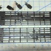
Here are the un-painted & un-lettered "old" Atlas car bodies...
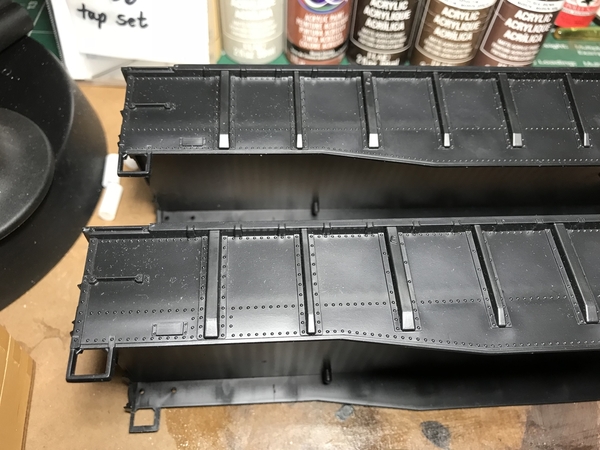
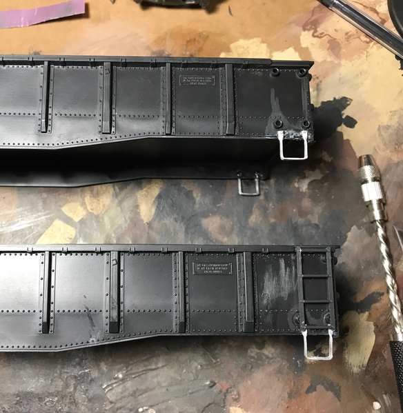
I wanted to replace the molded-in grab irons and over-sized stirrup steps, so I carefully shaved the grabs (leaving the "brackets") and cut the stirrups off. Here's a close-up "before" photo...
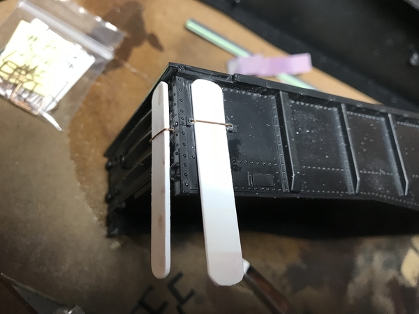
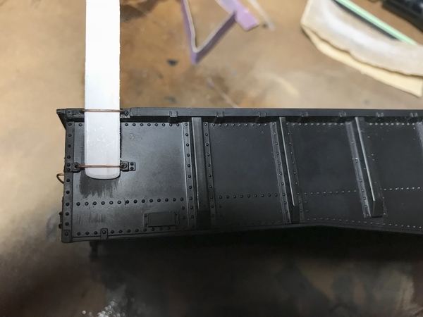
Metal wire grab irons from Tichy fit perfectly in the remaining "brackets". I knew this already from prior projects, and it certainly saved me some time not having to form them myself. All I had to do is drill the appropriately-sized holes and apply a drop of CA glue. The white styrene strips are homemade spacers I use to simplify the installation of wire grab irons. They make it very easy to consistently and quickly achieve the proper depth...
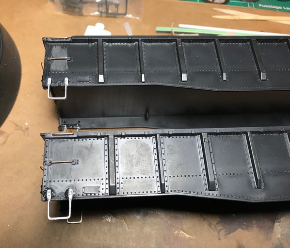
The metal stirrup steps are from Forum-sponsor Scale City Designs. Similar to the grab irons, I just needed to drill the appropriately-sized holes, add a drop of CA glue and press them in...
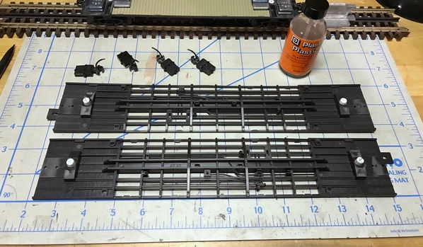
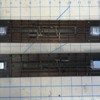
Now moving on to the under frames, removal of the Atlas stock plastic trucks and wheel sets leaves a large hole in the bolster (as pictured below) which makes mounting replacement trucks (in my case, Weaver die-cast friction-bearing style) a bit of a challenge...
My tried and true method of dealing with this issue is to drill the existing holes out (just slightly) to 1/4", then cut short "plugs" out of 1/4" solid styrene rod. I cut them a little longer than needed to make installation easier...I will deal with that later. The plugs are then glued in the holes and allowed time to dry/cure...
Next, the styrene truck-mounting plugs are cut flush with the bolsters and then a pilot hole is center drilled to accept a 2-56 self-tapping screw. At this point, I installed all of the underside details (brake lines, air tanks, etc.) included in the car kit as well as the Kadee couplers. I then added some 1/4" stick-on wheel weights (from Harbor Freight) and hot-glued them in place as I tend to over-build everything! Note: adding the extra weight is an optional step to improve the tracking of the empty cars. Adding a load will obviously accomplish the same thing...
The Kadee couplers were masked off and the entire under frames were painted with Rust-Oleum Camo Brown from a rattle can. Side note: this is one of my favorite paints. I use it as the base coat on the under frames of all my weathered cars. It dries very flat!
Moving back to the gondola bodies, I sprayed them with several light coats of Rust-Oleum Painter’s Touch semi-gloss black from a rattle can. Unlike water-slide decals, dry transfers are easiest to apply to a flat or semi-gloss finish...
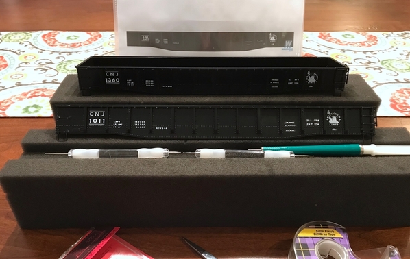
Unfortunately, I forgot to take pictures of the painted car bodies, so let's move on to the lettering stage. First, here's my decal application "guide" borrowed from the Walthers website ...
Good thing I had three sets of decals for only two cars...I messed up a couple times and had to do some sections over. Dry transfers take a bit of practice (and patience!) to find just the right amount of burnishing pressure. Despite using them for several years now, I still make an occasional mistake!
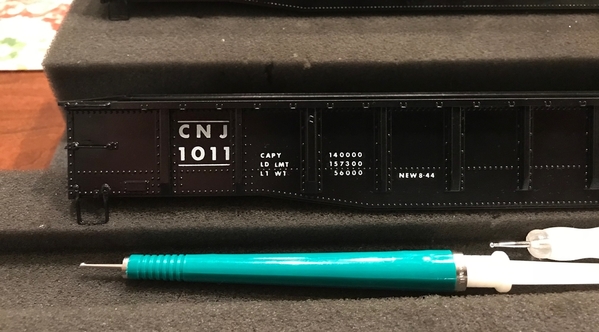
You can see some of the dry-transfer adhesive showing around the lettering in this close-up photo. That will disappear in the next step.
After finishing the lettering, I sprayed the car bodies with a couple light coats of Testors clear flat lacquer (Dull-Cote) to blend everything together and to hide the adhesive shown above...
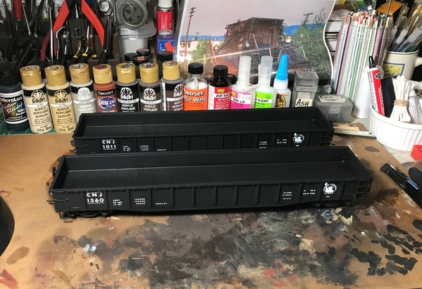
Here are the finished bodies and under frames...
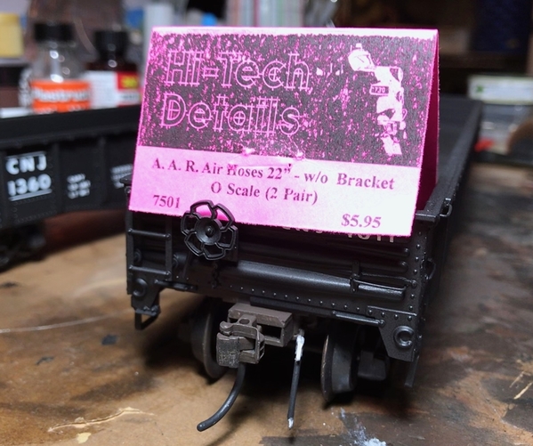
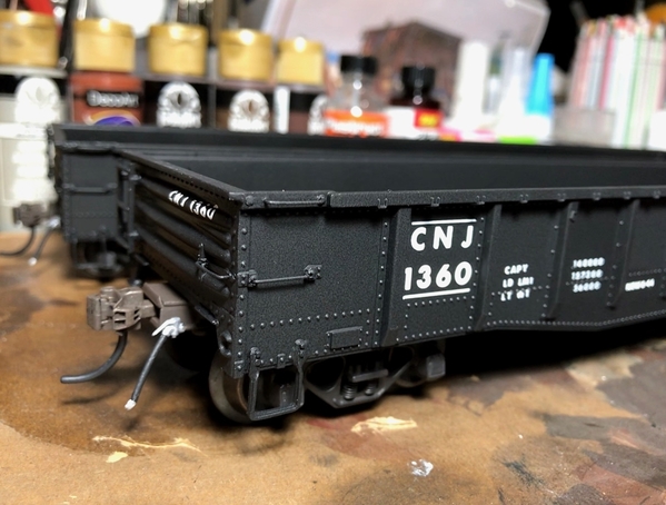
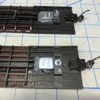
Before mating the car bodies with the under frames, I added brake line hoses/glad hands from Hi-Tech Details. It was my first time using them. They're made of rubber so they are very flexible (and durable!) and can withstand some rough handling. They are molded in black and surprising to me, they hold paint very well. I then painted, lightly weathered and installed the Weaver die-cast trucks. Here are a couple close-up shots of the brake hoses...
I messed around with some small washers from Micro-Fasteners to adjust the ride height to my liking. I wanted the car to sit as low as possible while still allowing the large 3-rail flanges to clear the under frame details. I then added Kadee coupler box shims from Micro-Mark to adjust the coupler height accordingly.
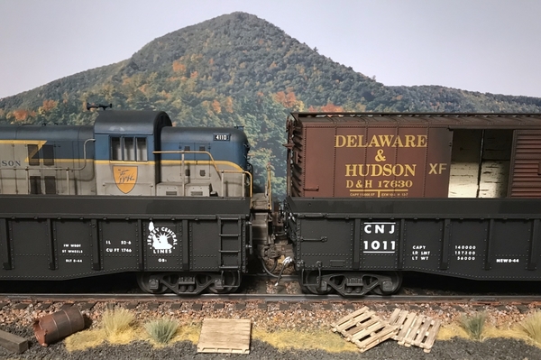
For those paying very close attention, yes, the coupler boxes extend a bit beyond the end of the car. That was an intentional compromise to allow these somewhat lengthy cars to negotiate less than the broadest curves. However, as seen in the photo of the Reading gondola below, it can be considered prototypical. Even with the extended boxes, I was still able to achieve fairly close coupling...certainly much closer than the lobster claws would have allowed!
Here are a few shots of the nearly-finished cars...
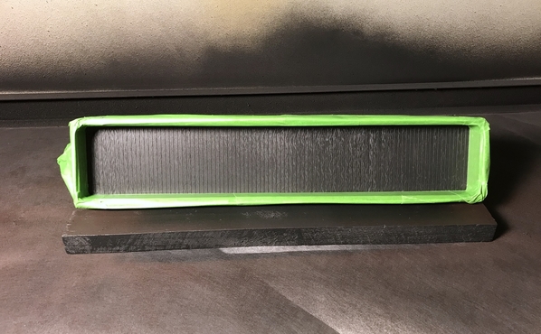
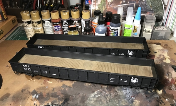
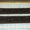
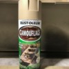
I used the words “nearly finished” above. After looking at the cars for a day or two I decided the simulated wood plank car floors were begging to be painted. Wish I realized this earlier in the build process, but never too late I suppose! I carefully masked the entire car and then sprayed with Rust-Oleum Khaki (another of my favorite paints) as a base coat. Here are before and after shots...
This was followed by a couple coats of a black and brown India ink/alcohol wash, then a couple coats of PollyScale Oak wash and finally a light coat or two of the Testors flat. I didn’t really fuss with the floors as these cars will eventually be weathered...and will probably receive some sort of loads. Here are some shots of the finished cars...
Thanks again for checking out this thread. If you made it to this point, I sure hope you found the information useful...or at least mildly interesting/entertaining. ![]()
Happy model railroading!


