
I'm working on my block controller now.  It will be able to monitor and control up to 14 blocks.  As a trailing train reaches the block behind the lead train, the voltage on that block would be reduced to about 6VAC so the trailing train decelerates to a crawl.

It occurred to me that this will also effect car lighting. I'm looking at designing a regulator module using a super capacitor to maintain constant voltage (or current) to lights for several seconds with up to a 50mA 12V LED load.  That will also eliminate any flickering as cars travel around the loop.

There is an inexpensive buck-boost regulator available from China that uses the XL6009, but I understand its output can go overvoltage when the input voltage falls below the XL6009 5.0V minimum spec.  Comments?

Jeff

Original Post

Replies sorted oldest to newest

You should look at a buck/boost power supply for that application.  It will tolerate voltages above or below the output voltage.  For most of them, you'll have to add a bridge rectifier and perhaps some additional input capacitance, depending on how much current your load draws.

eBay: 172357829700 for $1.64 shipped free.

Technical Parameters:
Model Specification: DSN6000AUD Automatic Buck Module
Module Properties: Non- isolated Boost (BOOST)
Rectification: Non- Synchronous Rectification
Input Range: 3.8V - 32V
Output Range: 1.25V - 35V
Input Current: 3A ( max ), no-load 18mA (5V input, 8V output, no-load is less than 18mA. Higher the voltage, the greater the load current.)
Conversion Efficiency: < 94% ( greater the pressure, the lower the efficiency )
Switching Frequency: 400KHz
Output Ripple: 50mV ( the higher the voltage, the greater the current, the greater the ripple )
Load Regulation: ± 0.5%
Voltage Regulation: ± 0.5%
Operating Temperature: - 40 ℃ ~ +85 ℃
Dimensions: 48mm x 25mm x 14mm ( L x W x H )/1.89'' x 0.98'' x 0.55'' ( L x W x H ) (Approx.)

I had looked at that one, but the specs on the XL6009 say 5.0V minimum.  Pursuing that further, reports show its output can go to 50V unregulated when the voltage drops below the minimum spec.  I suspect the module originally used the LM2577 because its specs do say 3.5V min.  There have also been reports of people ordering a module supposedly using the LM2577, but receiving one with the XL6009.  China probably just substituted the cheaper XL6009 without understanding it was not an exact replacement.

I'm looking at using a 5V regulator into a 5.5V supercapacitor, followed by an adjustable boost regulator.

Jeff

I didn't notice the other one was a different chip, here's eBay: 143186914163 that uses the LM2577 regulator.

I just ran a quick test on the buck/boost module and it does not exhibit any bad behavior. I see no spikes in voltage anywhere in it's range.

It's set at 12 volts and has a 48 ohm load, so it is supplying 250ma.  At around 3.4VDC, it starts regulating, though it's slightly low in output voltage to start.  By around 3.6VDC on the input, it's up to the 12VDC output and that holds all the way to 24VDC on the input.  Coming back down, at around 3.4VDCinput the output voltage starts falling. 

Obviously, with a 250ma load on the output at 12V, I'm seeing around 1.4A at 3.5VDC input, reducing to around .14 amps at 24VDC input.

Attachments

Images (1)
  • mceclip0
SGJeff posted:

.... I'm looking at designing a regulator module using a super capacitor to maintain constant voltage (or current) to lights for several seconds with up to a 50mA 12V LED load.  That will also eliminate any flickering as cars travel around the loop.

So from a design requirements perspective, you need energy storage of, say, 2 Joules.  That is, if you want to run 50 mA at 12V (0.6 Watts) for several seconds (let's call it 3 seconds), that 0.6W x 3 sec = 1.8 Joules.

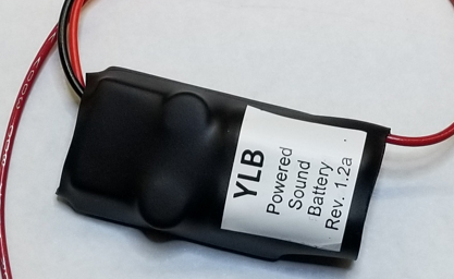
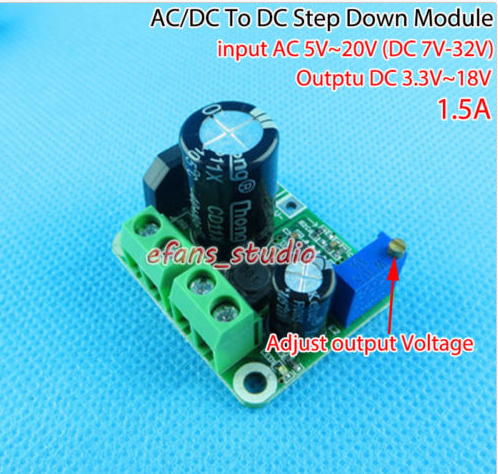
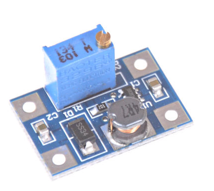
If energy storage is done with a 5V supercap (as done with YLB that GRJ mentions), an economically priced 0.47 Farad supercap would be more than enough.  That is, a 0.47F supercap charged to 5V stores about 6 Joules.  You can "read all about it" in the OGR design thread for the YLB here.  This would be if you go the route of a 5V regulator module, a 5V supercap, and a boost regulator module.  As discussed in the thread, consider some method (could be as simple as a resistor) to limit the supercap charging current when you initially turn on track power.  That is , if you have a handful of passenger cars with this "topology", you might get a whopping initial charging current (many Amps) if the 5V regulator attempts to directly drive a depleted supercap.

SGJeff posted:

I picked that up and will give it a test.  It is certainly cheaper than anything I could put together myself.  I can't even mail one across town for that price.

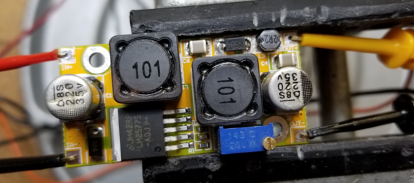
But if you're going with the buck-boost module, where is your 2 Joules of energy storage?  This would likely be done on the input side of the module since presumably you want constant brightness for the "several seconds" at 0.6 Watts.  But here's the rub.  That input-side capacitor must be able to handle full track voltage.  As the photo shows, they use a 35V capacitor (220uf) which is minimum rating for O-gauge AC operation.  Yet, when entering the 6V AC block, you might be  coming from, say, only 12V AC so the the 220uF cap might only be charged up to 15V DC or so.  15V and 220uF is a paltry 0.025 Joules...so ~100 times smaller than what you need!  So you'd need to increase that 220uF to something like a ginormous 22,000 uF capacitor (rated at 35V).

I vote for the YLB method.  I'd think the 3 major components, 1) AC-to-DC stepdown 5V module, 2) 5V supercap, 3) DC-to-DC boost regulator, should be in the ~$5 range if you're willing to do eBay from Asia suppliers.


Here's one solution, just stick your supercap between the two.  Should be as simple as sticking the supercap across the output of the first one, and I'd probably add an inrush limiter to slow the surge when the cap first charges.  Tie the supercap directly across the input of the second one, and feed the lights with the output.

eBay: 122880595090  AC/DC Buck Step down Adjustable Converter 3.3V 5V 9V 12V Rectifier Filter Module

eBay: 142976851135 DC-DC Boost Converter 3.3v 5v 9v 12v 2A Adjustable Step Up Power Supply Module

Attachments

Images (2)
  • mceclip0
  • mceclip1

I agree with you.  That's pretty much the design route I went down. I was going to diode-OR the super cap output with the 5V regulator output so the lights would come on as soon as track power is supplied, and the super cap would charge slowly through a resistor.  I already ordered some 1.5F super capacitors due to their lower ESR.

But it becomes a cost tradeoff.  I figure I could roll my own for under $10 each, including PCB, super cap, regulators, and passive components.  And that would keep a car illuminated for up to a minute with power removed.

But since my block controller will keep some power on the track, I think it may work OK with just a buck/boost regulator.  An electrolytic such as the 1000uF 35V I use in the electronic E-Unit only has to supply enough energy to prevent the flickering as the cars move down the track.  That's why I ordered one to test.

Jeff

While what we discussed previously was an elegant solution, I opted for a simpler (and less expensive) solution.  I had purchased a roll of 5V warm white LED strip.  A length long enough to fill a 15" passenger car pulls about 100mA at a reasonable brightness.  With that load a 1F super cap discharges about .1V per second, so the dimming is barely noticeable even after several seconds.  A resistor limits the charging surge, and a diode OR bypasses the super cap so the LEDs illuminate as soon as power is applied.  A cheap 7805 series pass provides the 5V, and brightness is adjusted with a trimpot.

So I’m doing leds in some mpc passenger cars. I got some xl6009’s and on a test with 12v dc in and my led light roll strip connected I could not lower brightness. I also got som lm2596 units and these drop the brightness nicely but provide no boost if the track power is low. I’m using a diode, cap and choke on the input to the board to get dc and some flicker control what’s the difference in these modules?

There are tons of ways to handle LED's in cars, my modules are just one way.  These are purpose built to use in passenger cars with the 12V LED strips.  Yes, if the track power is lower than around 9 VAC, you will start to lose brightness with my lighting modules.  You can, however, use 5V LED strips if you run conventional, then you'll be able to run at any voltage above about 5 volts on the transformer and still have full illumination.

NYCBuffalo posted:

I’m using a diode, cap and choke on the input to the board to get dc and some flicker control what’s the difference in these modules?

 You answered your own question.  I put the choke, bridge rectifier, capacitor, regulator, and intensity adjustment all in a module that measures 1/2" x 1" x 5/8" high.  Also, my module is a current mode regulator, so the adjustment is much less sensitive, with a voltage mode regulator, all the intensity adjustment is in around 1/10 of the adjustment range.  You go from very dim to full brightness in a couple of volts.  With my module, you go from around 3 ma to 45 ma over the full range of the adjustment pot.

I fold the tab on the regulator over the top of the cap when I install them.

Attachments

Images (1)
  • mceclip0
NYCBuffalo posted:

So I’m doing leds in some mpc passenger cars. I got some xl6009’s and on a test with 12v dc in and my led light roll strip connected I could not lower brightness. I also got som lm2596 units and these drop the brightness nicely but provide no boost if the track power is low. I’m using a diode, cap and choke on the input to the board to get dc and some flicker control what’s the difference in these modules?

If you want to both raise and lower the input voltage to some regulated-adjustable output then you need a buck-boost or step down up converter.  Think of buck as lowering or stepping down the voltage, boost as raising or stepping up the voltage.  For anything you'll find on eBay, the LM2596 is used in a buck-only configuration so it can only lower the output.  OTOH you'll find XL6009 modules that are boost-only or buck-boost.  And you'll find a good percentage of them mis-labeled on eBay.  For example here's two eBay listings that both say buck boost implying they can do what you're after:

buck boost vs just boost

The "true" buck boost has 2 black square components (inductors/chokes).  The 2nd board only has 1 and hence this is really a boost-only converter.

Attachments

Images (1)
  • buck boost vs just boost
Last edited by stan2004

Add Reply

Post

OGR Publishing, Inc., 1310 Eastside Centre Ct, Suite 6, Mountain Home, AR 72653
800-980-OGRR (6477)
www.ogaugerr.com

×
×
×
×
Link copied to your clipboard.
×
×