
I have found many ways to access a layout by searching here in OGR forums and on the internet. After weighing different parameters and limitations of many of these, and building a few hinged access ways, I decided that the lifting table offers the best means for my situation.

down

I spent a few weeks sourcing parts and drawing up plans. Due to lumber prices over the first half of the year and a lack of quality I have chosen to build with Arctic Birch plywood. There are 16, 3.625" (3.5 + plus 1/8" for kerf) wide cuts per 5'x5' sheet, and the 18mm (3/4") thickness runs about $70. I don't have to deal with any twisting and warping. The birch ply is prone to splinters so some light sanding is necessary on any sharp corners. Otherwise it is a joy to work with. Many of my shop cabinets are built with this product.

The legs are made from laminated from (2) 18mm and (1) 12mm strips. This results in a dimension real close to 1 7/8". This is also real close to the width of the heavy duty cabinet sliders. All other parts are 18mm plywood. The joints to the legs are mortise and loosely fit tenons, glued with liquid nails. (6/28/2021 edit: don't make the mistake I did, buy the $7 tube of construction adhesive. The $2 is easy to clean up but I'm finding some joints that have come lose, those joints are now pinned with screws through the tenons.)

This is the best approach for me to insure things come out square when I clamp them up. This table is within a 1/16" of being square in all planes. All of the cross bracing is secured with pocket screws, and they will be used on all other benchwork to come. The bracing across the lift section can be removed to allow carrying the two sides independently.

up

The dimensions are 66 3/4" wide x 48" deep. It stands 39" tall, for a finished height of 40" with plywood and homosote added later. The walk through is 38" wide and, with the arched stretchers, the height is almost 65". The finished side of the basement will not be totally dedicated to Turkey Hollow RR and will not be accessible from two sides so I need to be sure I have plenty of room for whatever may need to pass.

Sorry for the shaky video. I was trying to keep my phone still and control the table at the same time.

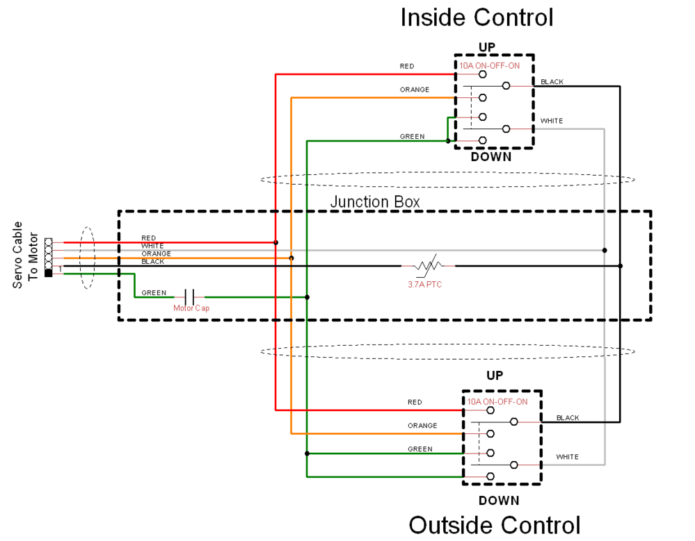
Next is to address the electrical side, low voltage control and the limit switch placements first. As others have done with these wide lifts, I intend to mount toggle switches on the inside and outside.

It has cost about $380 so far for plywood, hoist, pulleys, cabinet slides, levelers, toggle switches, and a couple of 5v relays.

Attachments

Images (2)
  • down
  • up
Videos (1)
lift_vid
Last edited by turkey_hollow_rr
Original Post

Replies sorted oldest to newest

Thank you guys! I appreciate it.

Tom and Gunrunnerjohn, I've learned from the experiences posted by you guys and have great regard for you both. I was tickled it worked out for the most part the first go around. I get to meld two of my hobbies, the other being woodworking. This is a few simple, square tables and no finishing work. Right in my wheel house. I pretty much did all of the milling with a table saw, tenoning jig, and hollow chisel mortising machine.

This is absolutely based on Mianne lift. I have great respect for that product and the price he can offer it for. It is very reasonably priced, imho. And you have support if you need it.

It took me the better part of 10 days to glue up legs, mill parts, and assemble, so I have a lot of sweat equity in this. It is a simple straight forward design, also used in cabinetry for tv lifts, etc.

I support DIY efforts when I can, I'm happy to share where I sourced parts. It may be possible to find better suited parts and get the price down.

The hoist is from flea bay. It is a light duty engine hoist. Besides being light duty rated it also has a decent rate, 26 feet per minute without a sheave, so it goes up and down at a reasonable rate.

In my internet searches I found these used to be available through WalMart and a few other places. My showed up with the head of one of the bolts mounting the hoist to the metal frame was snapped off. Probably why many places say "discontinued". Easy to replace but it got me a $10 refund. $70 bucks shipped. I just left the weight hanging, it helps keep tension on the cable a little bit.

hoist

I may have to re-address the hoist mount. It is only held to the table with two bolts through the plywood. It does flex on the bolts, the plywood doesn't flex.

Attachments

Images (1)
  • hoist

If you haven't seen this thread, you might want to consider it. Mianne Lift Bridge Lower Limit Switch Enhancement

I found while you can "usually" get the switches adjusted, the Mianne method of using standard momentary toggles with an angle bracket lends itself to easily getting "out of whack" and you have a real problem on the downward travel if the switch doesn't trip before the lift gate hits the stops.  This makes the downward stop about as bulletproof as I can imagine using simple switches.

The drawer slides are listed as 28", but they measure 27 1/2. They are rated at 100 lbs each. Cabinet parts dot com.

The pulleys took some looking. I almost went with old window sash replacement pulleys but these were much cheaper although overkill. These came from e rigging, surface mount pulleys. ~$48 shipped for all 6. They are 1" diameter at the bottom of the groove. It just worked out that 3/4" spacers result in about 1/4" peaking out beyond the plywood. I used a 3/4" mortising chisel to cut the openings and a 3/8 chisel to cut clearance for the rivet shaft.

pulley


The interesting part was what to do with the spring and weight on the cable just above the hook. This weight would move a lever and trip the limit switch when the cable was fully retracted. I cut the hook off and as show before I left the weight at the hoist.

This is what I came up with. In the up position there is spring tension but the bolt prevent fully compressing it.

up

When the table is down the spring tension is reduced and the cable end has little tension. If you look closely to the left of my finger you can see the pencil marks in the plywood where I measure how much movement there was at the bolt.

down

Attachments

Images (3)
  • pulley
  • up
  • down

Here are the parts for the low voltage control for the wench. Switches are from Digi-key, rated sufficiently in case I end up wiring everything 120 vac. Two normally closed SPST for the up and down limit switches. Two DPDT, (on) - off - (on) switches for control on either side.

I plan to wire in the 5 vdc usb chager to the wall socket side, hopefully with some spade connectors. This will power the two relays which are normally open and active low. That means the enable line just needs to be grounded to close the contacts. So the limit and side control switches are just grounding one side or the other to go up and down.

low_vdc_contol

My plan is to use a 4"x4"x4" junction box to house the usb power supply, the relays, and the motor cap from the yellow handle. That cap just needs to be wired across the blue and white wires from the motor.

I'm still working out in my mind how I might implement some kind of minute adjustment for the limit switches should it prove necessary. Perhaps in addition to angle brackets there could be a bolt threaded through the bracket with a lock nut on top. The bolt head would then make contact with the switch.

Attachments

Images (1)
  • low_vdc_contol

If you haven't seen this thread, you might want to consider it. Mianne Lift Bridge Lower Limit Switch Enhancement

I found while you can "usually" get the switches adjusted, the Mianne method of using standard momentary toggles with an angle bracket lends itself to easily getting "out of whack" and you have a real problem on the downward travel if the switch doesn't trip before the lift gate hits the stops.  This makes the downward stop about as bulletproof as I can imagine using simple switches.

John, I've drooled over that spring loaded, idler pulley and micro switch you used. I couldn't find anything like that. I also take heed of your warning on adjustment issues. I'm hoping what I did with the spring on my hoist will simply keep some tension when the cable goes slack, certainly won't stop an unwind.

I've also noticed a good deal of noise from the cable. It appears loosely wound and will grab hairs on your head, so I think the noise is from it tightening under load. It sounds like grinding gears but I'm sure it's the cable.

I'm still working out in my mind how I might implement some kind of minute adjustment for the limit switches should it prove necessary. Perhaps in addition to angle brackets there could be a bolt threaded through the bracket with a lock nut on top. The bolt head would then make contact with the switch.

Did you look at my thread?  The spring loaded switch sensing the slight slack in the cable really solved my problem of unreliable lower limit switch activation.  Obviously, the upper limit switch isn't all that critical, you just have to make sure you don't go past the point where you run out of travel in the cable or slides.

Below is how I wired mine for two-sided activation.  I did contemplate something much fancier with relays and interlocks.  However, upon reflection I figured that was gilding the lily and wasn't really needed.  I just wired the two switches in parallel, and then I inserted a PTC to guard against the unlikely scenario where two people were operating each switch in opposition.  This was a whole lot easier to put together than my first plan.  The PTC makes sure we never have a direct short with switches in opposition.

Funny you should mention the 4 x 4 box, I found one at Home Depot that was 4 x 4 x 4, I put the cap and PTC and all the junction of the wires in that box.  I pitched the yellow control handle, I had no use for a single control, my bridge is four feet wide.

Since there's four switch machines and power to three different loops on the lift bridge, I have loops of wire hanging between the fixed and movable sections of the bridge to bring power and control in, one set of wires on each side.

Attachments

Images (4)
  • mceclip0
  • mceclip1
  • mceclip2
  • mceclip3

I think we have a time lapse in our posts.

Yes, I've read that thread several times. I'll have to pay more attention to the cable play, maybe it can be done without the spring loaded pulley. The spring and washer on my cable may also work, unbolted that end moves about 1 1/4". Maybe that bolt should ride in a slot back and forth. You have me thinking more, glad I have plenty of time.

In my case the box is from Lowes. The mounting wings, size, and availability work nicely. I agree the low voltage isn't necessary if wired correctly. I'm just having some fun and doesn't cost $5.

Just saw your offer and thanks. That micro switch might just work with the sliding bolt. I'm out this evening getting my yearly free meal on the kid so I'll check in tomorrow.

Last edited by turkey_hollow_rr

Yep, I noticed while I was typing you were obviously answering as well.

I will say that detecting the cable slack was the silver bullet for me, that eliminated the tricky adjustment of the lame toggle switch limit.  It also insures the bridge is fully into the stops and aligned with the fixed section when the motor stops.

I actually had a design for a low voltage control that had all the 120V in the box, but it was more complicated than just using the two switches.  In the end, expedience won out and I went the simple route.  The PTC was my nod to making sure that I couldn't get a direct short with inadvertent multiple operation of the switches.

Dan, Something to sneak up and hit you in the face...precision deck alignment  We found it to be extremely critical for the two side foundational modules to be PERFECTLY level.  Not a single hair off.

Then, align all the other bench work to the lift assembly.  Consider using levelers on all platform legs to assist in leveling all the framework.  Shown are plastic faced Monoco swivel levelers and Tee nuts  available from Outwater Plastics in NJ.

IMG_8939

That good sized elevator surface will spotlight any off level surrounding bench work and make multi track alignment of the lifting deck unstable and unattainable.

Much less of an issue if only one track crosses the lift bridge.

Attachments

Images (1)
  • IMG_8939
@Tom Tee posted:

Dan, Something to sneak up and hit you in the face...precision deck alignment  We found it to be extremely critical for the two side foundational modules to be PERFECTLY level.  Not a single hair off.

Then, align all the other bench work to the lift assembly.  Consider using levelers on all platform legs to assist in leveling all the framework.  Shown are plastic faced Monoco swivel levelers and Tee nuts  available from Outwater Plastics in NJ.

IMG_8939

That good sized elevator surface will spotlight any off level surrounding bench work and make multi track alignment of the lifting deck unstable and unattainable.

Much less of an issue if only one track crosses the lift bridge.

Tom, thanks for the Outwater tip! Very interesting things there beyond levelers. Alas I have already purchased levelers and inserts from McMaster-Carr, enough for all of my layout plans. The ones I bought don't swivel and I had to add my own lock nut. Those Monocos are the way to go.

I assume that is a Mianne leg? I didn't notice the capping block before. I added 1/2 ply blocks to my table legs just to protect the the ends of the layers so they wouldn't split as I drilled the ends for the levelers. If there is one knock against the plywood it is that there more susceptibility to splitting between layers I guess Mianne is adding support for a lot more weight than my layout would provide.

leg

I understood going into this project the importance of (1) keeping four sliders in parallel over whatever length slider is used, (2) the force to lift needs to be centered to help assure (1).

I did get a feel for the level and plum reaction when I first began to operate the hoist. The table was a bit shaky as it started down. I found one leveler not fully seated and added extra bracing across the table. That really smoothed it out. The levers skate easily on the bare concrete (except the hoist side) and that works against keeping things in place while it's in the shop. It will be installed on berber carpet so that, and getting the side tables fastened to surrounding benches, should help with repeatability. It looks like it operates smoothly but as you suggest once I get to aligning plywood, track, etc, the warts will show.

Attachments

Images (1)
  • leg

Dan,  That leg in the photo is a 2 x 4 split diagonally with one half turned around and reattached.

IMG_8938<<< Opposite view

This arrangement stabilizes grain warping.

IMG_8940

The block of wood at the bottom of the leg??  Your assessment of my refinement is somewhat over stated!  I am a recycler.

My layout is built primarily from left over modules, reused modules from my last RR, modules graciously obtained from clients estates,  left over pre-curved side rail stock plus a stash of cutoffs.   Any new material came from pocket change.

Sooo... those blocks were added because the legs came off a layout built for a shorter customer.  The legs were simply an  1 1/2" too short for my new application.  (insert laugh track here)

Attachments

Images (2)
  • IMG_8938
  • IMG_8940
Last edited by Tom Tee

Add Reply

Post
The Track Planning and Layout Design Forum is sponsored by

AN OGR FORUM CHARTER SPONSOR

OGR Publishing, Inc., 1310 Eastside Centre Ct, Suite 6, Mountain Home, AR 72653
800-980-OGRR (6477)
www.ogaugerr.com

×
×
×
×
Link copied to your clipboard.
×
×