
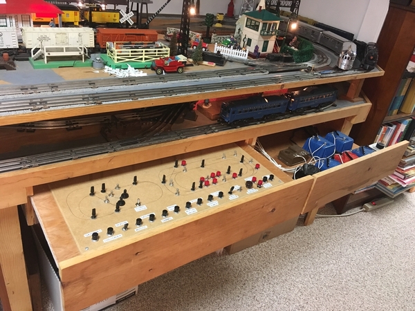
I completed a "semi-CTC" board to control yard and a scissor crossover turnouts.  Its semi because I do not control the layout signals, they change their indications as turnouts change position.   It is wired parallel with the MTH control system so turnouts can be changed from remote or locally.  The un-protypical yellow and green stripes aids the wife which way to turn the levers to route trains.  I found that I can preset the levers then press the code buttons to change turnouts when ready saving time scrolling through the remote switch menu

And for the rivet counter nit picker, on real CTC model boards, turnout levers are odd numbered and signal levers even numbered, but I ain't gonna crawl under that layout again rewiring things again just to conform.....

Here are pictures.  First photo is blurry as I don't know what camera was "looking at" (maybe shiny rails?).

DSC03551DSC03552DSC03556

And gasp, I documented everything for the "big book"!

!t ain't "purdy" but it works!!

Attachments

Images (3)
  • DSC03551
  • DSC03552
  • DSC03556

I used the Rix-Rax button/lever covers to make my panels look like CTC panels.    I have two.    The larger, black one is the main one.     The smaller one which is green, is for one town area = ie a separate tower.     On both, switches are the top row of controls.    you move the toggle to "normal" or "Curved" and then push the button below the toggle.   I have to use the buttons because I use twin coil switch machines, not motors.     Only switches on the main line are powered.   Others for industry etc are manual.    You can see the track diagram laid out in a straight line across the top.

The second row of toggles is for signals which are manually controlled.    These have 3 settings - "L" for left, "R" for right, and the center position is STOP for both directions.    The way it works is when you set it to "L", it clears (sets to clear or green) for trains going to your left as you face the panel.    And R works the other way.     The L and R settings are prototypical on many RRs according to a Signal buff buddy of mine.

The gap you see on the main (black) panel is the area covered by the Green panel representing Connellsville.


Main_Panel_5098IMG_5100

Attachments

Images (2)
  • Main_Panel_5098
  • IMG_5100

An interesting question gunrunnerjohn: How do you control your turntable with the LCS App? Follow-up question: I've seen some of your layout progress, and I'm pretty sure you use an Atlas O TT. Am I correct?

Yep, it's the Atlas TT.  I actually haven't gotten the TT control working on the LCS app, I was getting the switches working and the position feedback in place.  Since there's no electronic feedback of the Atlas TT position, I suspect I won't be able to actually get it to automatically stop on a specific whisker track.

Time to share the control panel from my meager 4ft x 12ft layout.  It's small but I've packed a lot of play-value into it.  (wish I had the opportunity to quadruple the size.... but alas, not for now)

My layout is in an alcove in the basement along an aisleway, thus space for a Control Panel was at a premium.  My solution was to place all controls onto slide out drawers.  One drawer for several small transformers, and another drawer for Switch Control, Block Activation and Accessories.

My Layout is basically a Post War Layout, where I run antique, post war and modern trains (without command control).  Small transformers work well for me due to space (ever try to put a ZW in a sliding drawer?)  For whistle and horn activation I added push buttons across the front of the Transformer Drawer which interrupt the AC power and send momentary DC to the track.  Three trains can be run simultaneously and are thus controlled by three different transformers, but everything is In-Phase so trains can transition from track loop to another.  Additional transformers provide power for Turn-outs, Accessories and Lights.

The Controls Drawer shows the Schematic for both the Upper Level and the Lower Level.  Black toggle switches to control the Track Turnouts, silver toggle switches to control power to each Block, and red pushbutton switches for magnetic un-couplers.  Accessories are activated by switches across the front of this drawer.

Since everything is movable, all wires going to and from the drawers are flexible multi-strand wire, which go to terminals on a vertical panel between the two drawers.  From there, solid strand wire proliferates to everywhere throughout the layout 

Enjoy!


Attachments

Images (5)
  • mceclip0
  • mceclip2
  • mceclip3
  • mceclip4
  • mceclip5

Do any of you that use DCS and DCC, walk around with remote controllers and have a layout with 10 or so track switches use track diagram control panels for track switch operation?

Example below

My Trains 4-18-2016 014

They would make identifying the switches to be activated, for a given route of the train, easy and quick and more accurate (less switch throwing mistakes) versus a line of Lionel track switch controller.

Charlie

Last edited by Choo Choo Charlie

Add Reply

Post
The Track Planning and Layout Design Forum is sponsored by

AN OGR FORUM CHARTER SPONSOR

OGR Publishing, Inc., 1310 Eastside Centre Ct, Suite 6, Mountain Home, AR 72653
800-980-OGRR (6477)
www.ogaugerr.com

×
×
×
×
Link copied to your clipboard.
×
×