Every model railroad question I ever had was better discussed and resolved on the OGR Forum than anywhere else. For that, and much more, I am grateful. I would like to pose a design question for all of you civil engineers that will go a very long way in helping me to resolve some thorny design issues. 


I have come to the conclusion that I must construct a double deck layout to achieve the design goals for the "New Munoz Lines," model railroad. The requirements I have set for myself are daunting, but the resolution will require two decks . . . . . . . Sigh


I would like to build very strong benchwork and it must be modular. The layout itself cannot be supported by any walls and will be approximately 16' x 30'.  It must be a free standing island design.  I would like to solicit suggestions from you about how to support the upper deck, install good lighting for the lower deck, and avoid view blocks on the lower deck that would obscure the enjoyment of the scenery and trains. I am thinking 2' x 4' vertical members as the backbone with strong vertical brackets installed on the 2' x 4's that would hold metal shelf supports. The upper deck would be supported by the metal shelf supports and the fascia for the upper deck would be sufficiently high to "hide" the lighting for the lower deck. If anyone can draw a sample module showing the benchwork design/support system, perhaps 3' x 5', I would be very grateful !! Many thanks.

Eliot "Scrapiron" Scher


Original Post

Replies sorted oldest to newest

Some general ideas for double-deck layout design:

* The upper shelf would be narrower than the lower shelf (over most of its length) so it doesn't excessively overshadow it.

* The lower shelf should not be so wide that it makes access to the upper shelf overly difficult.

* Supports for the upper shelf should preferably be minimum vertical depth for aesthetics and space efficiency.

* Clearance between the upper and lower shelves should strike a balance between good access and good viewing for both levels, and efficient use of space.

As part of your design process, I would suggest that you experiment with improvised shelves of different widths at different elevations, to determine basic dimensions that suit you. These dimensions will have a bearing on designing the support structure. 

What minimum radius are you aiming for in your 16' x 30' layout space? Would you anticipate having one duck-under/movable bridge section?

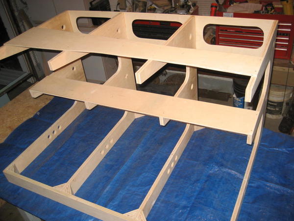
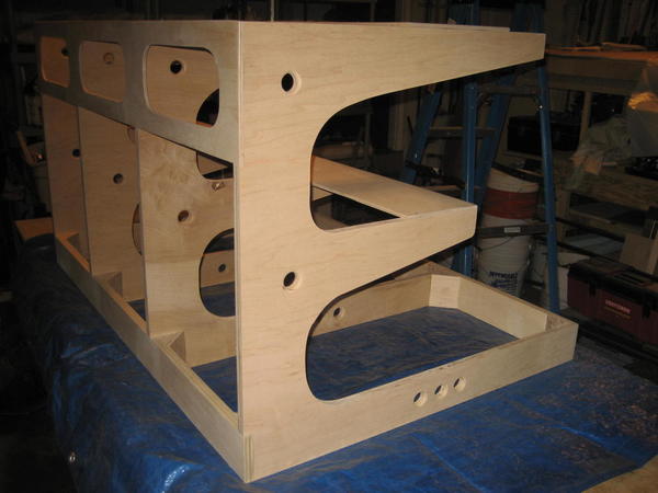
I"m not sure this is what you're looking for, but here's a few early construction pictures of how I did my levels. Basically I cut plywood cookie cutter style to fit the tracks and elevated them with 1X2's.  Some of the 1X2's will be covered by hillsides and any exposed supports will be blended in somehow or replaced with something fancier.  I secured the roadbed to the supports with 1 1/4" drywall screws.  Make sure, if you're double tracked, to place the screws between the the tracks in case you want to make changes.  That way you don't need to move track to replace or move a support.  Guess how I learned that!!  Since it is double tracked, the weight of the structure plus the curvature around the layout is all it needs to be secure.  After 14 years it hasn't moved unless I move it.  You can even put a drop of carpenter's glue under a few supports to help secure it.

For wiring I just ran the feeders below the main bench work to bus wires.  Again, the wiring will be behind scenery eventually.  Anywhere not covered by scenery I secured the wires behind a support and down through the bench work.  Hope this helps!

P2263562P2263563MTH BridgesNW Area

Attachments

Images (4)
  • P2263562
  • P2263563
  • MTH Bridges
  • NW Area

The most important factor in the design in my opinion is to plan for sufficient lighting.  I was not happy with strip leds.  Some of them began to dim after considerable use.  Ultimately, I reverted to nice track lights with leds in them.  I wish I had left a little more room.  Since you are planning for an island type, you will probably have more of the lower covered up than some of the posted plans, thus lighting is crucial.  Good luck. 

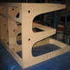
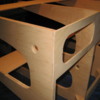
Actually all the parallel edges and inset recesses were cut on a table saw.  All the arm tips were cut on a chop saw.  All the curvatures  were cut with a Bosch jig saw then cleaned up with a spindle sander.  The recess notches were cut with a table saw and trimmed with a jig saw.

The angled lower edge of the 2nd and 3rd level fingers were cut with a chop saw.

This type of fabrication will produce a fair amount of scrap which will be needed for risers.

Something to consider:  Cut a notch out of the side or end of a 4 X  8 or a 5 X 9 table and inset your table saw and / or chop saw with the deck flush with the plywood.  Now you will now  have a nice cutting table for fun cuts.

Keith, I'll take that wager. 

At a show one time someone asked if I used a C.A.D.  My wife responded "No, he uses a T.O.M."

Anything I build can be done with very common big box tools.

Another way to incorporate a table saw with a table is to use a pair of 10' long mid height leg braces which would extend 2' off the end of a 8' long table at a height which a contractors table saw could be set to provide a flush take off surface.

I used this at the entrance of my shop where I could back up a vehicle and rip panels as I pulled them off the truck bed.  Makes for a convenient one man operation.

Last edited by Tom Tee

Add Reply

Post
The Track Planning and Layout Design Forum is sponsored by

AN OGR FORUM CHARTER SPONSOR

OGR Publishing, Inc., 1310 Eastside Centre Ct, Suite 6, Mountain Home, AR 72653
800-980-OGRR (6477)
www.ogaugerr.com

×
×
×
×
Link copied to your clipboard.
×
×