I have a couple of dummy locomotives to do, and given the costs and issues with some of the dummy locomotive boards, I though it would be nice to use an R2LC, I have a bunch of them hanging around, especially the slightly older R2LC-C07 versions. Other than a reversed polarity on the lighting outputs, they're pretty much the same as the R2LC-C08 versions. So, all I need is a convenient way to connect them to the dummy wiring.
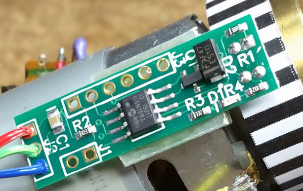
Here's my solution.
The .01 caps provide a load for all the triacs on the R2LC so that LED usage is possible without added load components. The PCB fits under the R2LC and provides convenient connection points for the inputs and outputs without adding to the overall footprint of the package.


I ordered a bunch of boards, we'll see how fast the Chinese can ship them. ![]()