
**** EDIT ****  Attached all the finished files to this post and updated the description to match the finished board.

I've started a new project to have a more functional way to do dummy locomotives with TMCC capability. It is also capable of being used in powered locomotives to add some features not commonly available with TMCC.

I have created a custom motherboard that will offer the following features.

  • Smoke & Directional Lighting Outputs
  • Electrocoupler Outputs
  • ERR Compatible Sound board Interface (4-pin JST-EH connector)
  • Logic outputs to indicate motion, forward, reverse, or stopped.
  • Separate 5VDC output for extra external functions
  • Buffered serial data to avoid data loading problems on the serial data line
  • Optional powered option with DCDR PWM outputs
  • DCS compatibility, will not interfere with DCS locomotives
  • TVS protection diode to protect the electronics

The motion logic outputs for forward and reverse indication are 100% optically isolated so you can use then in a wide variety of ways.  The opto isolators have diodes for DC reverse current blocking, and will sink at least 50 milliamps.

The 5VDC supply allows you to power external logic to do a unique task without having to provide a separate power supply.    It's possible to use the venerable LM7805T (or similar) to provide the 5V power.  The board is also sized for the Recom R-78E5.0 switching regulator module for higher output currents.  The switcher is obviously more expensive than the three terminal regulator, so unless you need it, the regulator is the cost effective choice.  If you plan on using more than 30-40 milliamps of +5VDC, then you need to add a heatsink to the LM7805T regulator.  If you opt for the Recom R-78E5.0 switching regulator, you have several hundred milliamps of +5VDC power available.

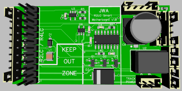
Some might question the odd placement of the components and why so much blank space.  It was planned, the blank sections are where the R2LC has tall components that typically sit right on the motherboard unless you have tall posts.  Since I didn't want to make the package any larger than it needed to be, I just put my logic in places there is clearance from the shorter components.  The white line down the middle is where the end of the R2LC board falls in case you wonder what it was for.

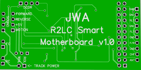
After measuring the R2LC & R4LC boards, I established keep-out zones for any parts as those the the tallest parts on the R2LC/R4LC.  In the other locations, there is room for the low profile SMT parts without any conflicts.  I also moved the one connector to the end by the R2LC connector, this makes it easier to route the heavier traces for the power and smoke functions.  The board is 1.25" x 2.5".  The power connection is a unique type of connector so you can't inadvertently connect the track power to one of the coupler outputs.

R2LC Smart Motherboard v1.1 3D T

R2LC Smart Motherboard v1.1 3D B

Build Files for R2LC Smart Motherboard

R2LC Smart Motherboard v1.1 Gerber.zip

R2LC Smart Motherboard v1.1 Schematic.pdf

R2LC Smart Motherboard v1.1 Assembly Diagram.pdf

R2LC Smart Motherboard v1.1 BOM.pdf

Attachments

Last edited by gunrunnerjohn
Original Post

Replies sorted oldest to newest

Net yet, I just wanted to toss the initial design out to see if it resonated or folks told me I was crazy.

I did think of adding another connector for the PWM motor outputs, that would make this useful for powered units and give you some added functionality. 

I may also add a buffer to the serial data as adding serial stuff sometimes overloads the serial line.  I'm thinking an op-amp circuit with a 2x gain to give me a nice 5V rail-to-rail serial data stream with more oomph so that it'll drive multiple inputs.

Well, the motor outputs are just the PWM signals from the R2LC, I'm not suggesting I'd add motor drivers!  I have wired a few diesels with a simple motherboard and the Cruise Commander M board.  The reasoning is that the CC-M has ditch light outputs, so I can have fully functional ditch lights.  With the addition of one 4-pin connector, I cover that base.

Well, the motor outputs are just the PWM signals from the R2LC, I'm not suggesting I'd add motor drivers!  I have wired a few diesels with a simple motherboard and the Cruise Commander M board.  The reasoning is that the CC-M has ditch light outputs, so I can have fully functional ditch lights.  With the addition of one 4-pin connector, I cover that base.

I miss read. I thought you were adding motor drivers as well. 

I was thinking about the 5V output.  I think I'll do a little rearranging and give room for a little switching module, the one I use on the Super-Chuffer.  It has the same pinout as the LM7805T, just needs slightly more room on the board.  Of course, if you're drawing more current, another consideration is making the filter caps more robust, that's another limiting factor.

I thought about the design overnight, and I realize that I will have to shuffle some things around, but I'll keep the capability the same.  I do want to buffer the serial data as I've had issues in the past overloading the R2LC output data line.

It's still a "work in progress", but I've been thinking about this for some time.  I know there are tons of R2LC's wasting away in various parts boxes, and this is a cheap way of reviving them.  I also thought about the current requirements for stuff like smoke, and I'm going to rearrange things a bit to make it easier to route stuff with heavier traces.

If you don’t already have them on this board, would adding a TVS diode to the board for protection against voltage spikes and adding a PTC to the board to protect against derailments where the rollers are shorted (one roller on center rail & other roller on an outside rail) be worthwhile?  The PTC would mean using a three position connector rather than the two position shown along with modifications to the board traces.

Yep, I do that a lot for passenger cars because the wiring they use in many of them is very small.  If you're using the typical 22ga wire for an engine or dummy, I don't see adding to the PTC for that.  Besides, one of the issues in bringing the current through the PCB is the potential for cooking traces on the PCB.

OTOH, I could see possibly having a PTC in the power lead that protects the PCB.  If the user wants to protect his wiring, he can add his own PTC.

Last edited by gunrunnerjohn

I bet folks with four motor AA PS1 locos or dead PS2 5V boards driving a slave board and four motors in MTH four motor AA units would go for a motherboard with plugs for two DCDRs to replace what ever was in their MTH 4 motor locos.   I was adding 15A triacs and a better heat sink  to TAS cruise boards but have used my stash and not found any lately.          j

@Jim Sandman posted:

Useful to have one sitting around to test R2/R2LC boards if you don't already have a test setup.

Got that covered Jim.   I started with a simple motherboard, and I keep adding stuff as new situations come up.  I can test virtually all the TMCC and many modular Legacy boards on this rig now.  My only regret is if I knew it was going to grow like this, I'd have probably planned the layout a bit better.

JWA TMCC Test Fixture

@JohnActon posted:

I bet folks with four motor AA PS1 locos or dead PS2 5V boards driving a slave board and four motors in MTH four motor AA units would go for a motherboard with plugs for two DCDRs to replace what ever was in their MTH 4 motor locos.   I was adding 15A triacs and a better heat sink  to TAS cruise boards but have used my stash and not found any lately.          j

I'm pretty sure to drive two DCDR, DCDS, or CC-M boards, you'd want to buffer the PWM outputs.  They feed opto-isolators, and the load of two of them is likely to cause issues with the amplitude of the R2LC outputs.

Attachments

Images (2)
  • mceclip0
  • JWA TMCC Test Fixture

I haven't gotten the boards back yet, they're supposed to be on their way for Monday.  It did get to test the serial data buffer/amp circuit as I did a little PCB with just that on it. 

My first attempt at serial data buffering with a 2x amplification was a bust, it didn't work at all!  Then I looked closer.  Turns out the Microchip op-amp I was using had a dizzying array of different pinouts for their part, even with the same footprint!  I happened to pick one pinout for the board layout, but another one for the actual part!  I truthfully still couldn't figure exactly which package ordering option was supposed to be the pinout I was using from the datasheet.  Since I had a TI part with the same footprint and without the confusing multiple pinouts, I used that.  It worked perfectly and did exactly what I expected.  Very annoying that the Microchip part was so obtuse in their datasheet!   That being said, I'll be using the TI part in both the MB and my separate serial port buffer.

Monday I'll have the motherboard, and I have a project on my bench that needs two of them, so that will use up two of the three I ordered.

I just got a prototype sound board with a new interface I'm trying, but I'm still waiting on chips.  I am going to finalize it and have a quantity assembled as I think sound boards are in demand.  This is a 1.9" x 1.2" board that used a canned MP3 sound board and has five optically isolated inputs for five sound clips.  It also will offer an option to plug in a 4-channel RF receiver for remove control of the sounds.  The MP3 module plugs into the two headers on the right, the RF receiver on the bottom left.  I'll have more to say when I get the chips and can do a test. 

Attachments

Images (1)
  • mceclip0

I was looking at my motherboard and thought, gosh it would be cool to have the ability to have the "motion" output indicate stopped instead of motion.  Turns out, that was easier than I thought.  I can just swap the XOR gate for a NOR gate and it inverts the sense of that output.  Now it's useful for automatic control of a cab light.  If you want an indication of motion in either direction, you just tie the two "forward" and "reverse" outputs together, they're open drain FET's, so that works great.

I haven't put it together yet, just got the three boards.  I happen to have a project in-house that I need two motherboards for a couple of dummy locos, so I'm going to assemble just what I need on those and ship it out.  The third one will get the whole chip complement when I get my Digikey order later this week and I'll give it a test.  I think I'll wire up a little test harness with some bulbs so I can exercise all the functions.  If that test works out, I'll do a final "look around" and make any tweaks and then order a larger quantity of boards from one of the volume board makers.  Paying $5/ea from OSHPark ain't gonna' do it, I'd rather pay 60 cents each.

I'm not sure what a video will do, it's just going to control lights and in one of them, the sound board.  The two are going to be "stripped" motherboards, they won't have anything but the three small caps that load the lighting and smoke triacs so my LED lighting will work.  Other than that, they have the 10 pin connector, the four pin sound connector, and the two pin track power connection.  I just jumpered the serial data buffer as the R2LC on the one with sound is only driving the ERR RS Commander and nothing else, so no buffering needed.

Obviously, this is only the motherboard, you do need an R2LC (or R4LC-C08), and all the other stuff.  Here are the first two boards, the 3rd will get all the parts and be my true beta test.  I just needed a couple motherboards for this job, and these happened to come in the door.

Attachments

Images (2)
  • mceclip0
  • mceclip1

Testing was... interesting.  Got it all assembled and connected the transformer.  Applied power and POP, the breaker tripped!  OK, that's not good!  Turns out that Digikey sent me silicon diodes instead of the TVS diodes I ordered!  Same physical package size, and since the package has the correct part number and the faint numbers on the device didn't mean anything to me, I "assumed" they were correct.  I "assumed" wrong!  Removed the TVS and things got back to normal, the power LED came on, I had good serial data through the buffer circuit, and of course lights and couplers appear to work just fine, they're just wires.  I then took the "TVS" diodes over and tested them independently, they are ordinary silicon diodes.  I couldn't find any match to the numbers on them on Digikey or even the rest of the Internet, I just assume they're probably 3-4 amp silicon diodes from the size.

One down, let's do some actual testing.

Sadly, my circuit that detects when the train is stopped or moving, and which direction, didn't work at all.  I did see very small indications on the LED's that it was sensing direction, but the stopped light stayed on all the time.  I broke out the scope and made a little revelation, I should have looked more closely in the design phase.  The PWM circuits do a very odd thing, which explains why I was having a problem.  The direction you're going has the line sitting at 5V and going to ground for the variable pulse width time.  However, the other direction has the line sitting at ground.  Actually, it was open and just floating, I found that out soon after!  I had been looking at the active PWM output and falsely "assuming" the other one just sat positive when it wasn't active.

Given that behavior, I had to swap the trigger input pins on the multivibrator chip to get it working properly.  Well, that entails changing four wires on a small SMT chip, cutting tiny closely spaced traces, etc. with everything already soldered to the board!  It's not pretty, but I did get the wires rerouted.  I also noticed that I had a couple orders of magnitude error in my computations for the pulse width out, so I had to lengthening it 100x for it to cover the 10 millisecond time span between the PWM pulses, time for a much bigger resistor.  OK, all that's done and the reverse direction works great, the reverse movement LED comes on, and the stopped LED goes off.  Cool, I have it working!  Try it in forward, not so good.  Both the reverse and forward LED's come on!  That's not right!  I put my 'scope on the two PWM inputs to see what's happening and it starts working correctly!  Take the 'scope off and it screws up again.  Ah Ha!  Remember those "floating" PWM outputs?  Enough noise was getting coupled to the very low power input of the multivibrator reverse trigger to trigger it when I was going forward.  Obviously just a product of how the board traces were routed for that side.  A 1 meg resistor to ground fixed it, so that's the issue.  I decided to actually go with 100K to ground in the next spin to insure this doesn't rear it's head.

Now with all the wires hanging off and the extra resistors hanging off the back, it works like I originally intended.  The only minor quibble I have is when you switch directions, both direction lights momentarily flash and then everything is normal.  This is a byproduct of the fact that the active direction changes the state of the PWM output from floating to +5V and the other direction goes from +5V to floating.  That would be harder to fix, so I'm going to ignore it, it really isn't a major issue.

Timing was good, I used up the three boards I got from OSH Park, so now I'll order a slightly larger quantity of the next spin, maybe from SEEED Studio, they have a pretty cheap deal.  I don't want to spend too much on boards yet until I get one fully working with no hacks.

Not too bad for the first cut, but I should have been a bit more careful in my initial design and I could have avoided most of this except for the bad TVS.

Very interesting John, a steep "development curve" for sure! Very strange that digikey would have shipped the wrong part for the tvs's. That doesn't seem to happen often. I have only ever ordered tvs's from Mouser, and they have been correct. Good lesson there I guess.

Good that you were able to make the other circuit mods and get the logic working as intended. The short flash of forward and reverse leds doesn't sound too serious. Overall the outcome sounds great! Looking forward to the next installment for sure! 👍

Rod

I've only had a couple of instances of incorrect parts from Digikey, they're normally very good about accuracy.  No worries, I'll have the TVS before I have board blanks again.

I did find one more issue I have to think about.  Everything works perfectly "until" I connect a DCDR to run a motor from the MB.  Then the forward/reverse circuit doesn't work until you have considerable speed.  The reason is that the DCDR has opto-couplers to receive the PWM signals and this hammers the amplitude of the PWM signals sufficiently so that the trigger inputs of the '123 multivibrator don't reliably trigger.    I think the only way around this is to buffer those outputs to the DCDR output so they don't affect the R2LC signals.

This should be the last issue (famous last words).  The sound boards work, the 5V power is fine, and all the basic R2LC signals don't have any issue.  With the fix for the motion feature, that's the one remaining issue I have to look at. 

Someone had asked if you could parallel DCDR boards off one R2LC, I think from my observations, the answer is probably no.

I did find one more issue I have to think about.  Everything works perfectly "until" I connect a DCDR to run a motor from the MB.  Then the forward/reverse circuit doesn't work until you have considerable speed.  The reason is that the DCDR has opto-couplers to receive the PWM signals and this hammers the amplitude of the PWM signals sufficiently so that the trigger inputs of the '123 multivibrator don't reliably trigger.    I think the only way around this is to buffer those outputs to the DCDR output so they don't affect the R2LC signals.


John, how about using something similar to your serial data buffer circuit to amplify the PWM signal amplitude to mitigate this problem? Or would that be too many patches?

Also I think a single DCDR/S is good for 10 amps total motor output, so maybe running two from one output is a moot point?

Rod

I'm putting a buffer in to drive the DCDR outputs, and taking the internal signal from the R2LC.  That solves the problem without having to worry about the voltage drop.  I'm thinking this has gotten to the point where the only practical way to use it is to get them assembled, it's a lot of fine part soldering if you build it yourself!

R2LC Smart Motherboard Rev. 1.1 Schematic

R2LC Smart Motherboard Rev. 1.1 3D Top

R2LC Smart Motherboard Rev. 1.1 3D Bot

Attachments

Images (3)
  • R2LC Smart Motherboard Rev. 1.1 Schematic
  • R2LC Smart Motherboard Rev. 1.1 3D Top
  • R2LC Smart Motherboard Rev. 1.1 3D Bot
Last edited by gunrunnerjohn

I just made a scratch file set and changed all the footprints from SMT to thru-hole.  Not a perfect conversion, but close enough to see what you'd be up against.  You can see the original board on the left, and all the components are yet to be placed.  I'm not going to bother because I can see how big it would get.  Also, the router has more issues with thru-hole as the parts go through, so you can't run wires on the other side.  The width of the board is limited to what's there, 1.25", you can't make them wider and fit in many locomotive shells.  So, the board would be about twice as long, around 5".

Now you see why the stuff is surface mount, even the old 1990's stuff.

Attachments

Images (1)
  • mceclip0

There is solder paste that is used for volume SMT production.  The problem is, to really use it you need the stencil and you put it on with something like a rubber putty knife, the stencil just allows it to coat the actual pads.  Then you just carefully position each part in place and use IR or a hot air tool to bond them.  The solder paste is expensive, it needs to be refrigerated, and it only has a shelf life of a few months. 

If you ever get to visit a PCB fabrication plant, it is interesting how they do this in volume.

For hand assembly, what I do for most SMT parts is tin one contact, bring the part into alignment while heating that pad.  When it's aligned, I remove the iron and then just solder down the rest of the leads.  For chip resistors and caps, I get the one side soldered, then apply gentle pressure and touch the bond again to seat them on the board, then solder the other side.  Needless to say, this requires a very fine tip for some of the chips.  I also limit myself whenever possible to the .95mm lead spacing or larger for my designs.  I can hand solder those, the parts with 1/2mm lead spacing are just too difficult to do repeatedly.  I've put a few audio amps on PS/2 boards, but it's a royal PITA, and I don't look forward to it.

Last edited by gunrunnerjohn

I'm going to have to do one more prototype I think, I made a number of changes.  I added the buffer for the DCDR signals, hopefully that puts that issue to bed.  I also need to do one more experiment, I think I may have a way to eliminate the random triggering of my outputs, and it's the proper way to do it anyway.  I think if I just pull the DCDR outputs to 5V instead of tying them to ground, I'll eliminate the floating line issue, and since they're always high, I won't get the flashing of the outputs.  I have to chance my hacked MB to put that fix in and see how it works.  I also fine tuned some spacing issues that I had.

I'm also toying with an idea of upgrading the motion outputs...

Attachments

Images (2)
  • mceclip0
  • mceclip1

There's a way, but I don't have time to write the code to do that.  It's on my "to-do" list, I'd like that capability as well.  That certainly won't make it into this project.

On the bright side, I did swap my load resistors from ground to the 5V supply, solved the problem of the blinking outputs when switching directions as I expected. 

The remaining thing I'm looking at is a opto-coupler for the forward and reverse outputs.  This would allow automatic Rule-17 lighting control, it would just add a resistor in series with an LED headlight when stopped and jumper it out when moving.  My existing FET design doesn't allow that capability, so I'd like to have that included.  This would give you automatic cab light control and Rule-17 lighting capability, something I like to add to upgrades.

Last edited by gunrunnerjohn

Well, here it is, it has gotten about as much functionality as I can cram in.   For the curious, I attached the current schematic.  I added the opto-couplers so the forward and reverse motion outputs are totally isolated.  This gives you greater flexibility in using them for various functions.

R2LC Smart Motherboard v1.1 Schematic.pdf

R2LC Smart Motherboard v1.1 3D T

R2LC Smart Motherboard v1.1 3D B

Attachments

Last edited by gunrunnerjohn

The deed is done!  The previous post's prototype is the final product.  The boards and parts all arrived today.  I sat down at the bench and built one up and put it through it's paces.  All the features work as planned, and the motor drive and audio interfaces all function perfectly without upsetting the added lighting output functionality.

Here we go, successful bench test!

You can see the small proto board on the right, that has the smoke (kinda' dim, it's an 18V bulb), forward and reverse lights.  The red, green, and white LED's are the reverse motion, forward motion, and stopped.  I'm driving an ERR RS Commander and using the Lionel DCDR to spin the motor.

After hand building this one, you'll probably really want one of these to take the time to build one by hand!  It's possible for a 77 year old to build one, so you should be able to successfully compete one if you have a steady hand, desk magnifier, and are a fairly accomplished solderer with a good fine tip iron.

Last edited by gunrunnerjohn
@cjack posted:

Ordering details?

Funny man!  I'm not going to hand build these!  I think that would certainly make them price-prohibitive!  It took about an hour and a half to slap this one together.  It's a cool project with lots of added functionality, but it's hard to say how big a market there really is.

I was mulling over the possibility of doing something like I did with the TMCC buffers.  Seeing if I could round up enough pre-orders to get a factory build of a batch of them.  That would be the only practical method I think.  I certainly don't want to front a thousand or two dollars in the hopes that I'd sell enough of them to break even!  The smallest practical run in terms of price is probably 100 units, if I had pre-orders for at least half of them, I might shoot the dice and have a run of them done.

I'm going to get the new and properly sized parts in and build one more to make sure everything fits properly, then I'll make up a package of documentation for download and offer the boards.  I'll also make the Gerber files available for anyone that wants to make more after the batch I have is gone.  I fudged a couple of parts when I didn't have the exact match in my parts stash, but nothing that affected the operation, a couple of 805 resistors in place of the 603 resistors.  However, I'd like to have one built with all the correct parts.

Another point with this board.  While it has all sorts of whistles & bells, you can also just populate a minimal board with a couple of the connectors for features you use, and jumper things like the serial data buffer if you aren't loading the serial data too much.  That's exactly what I did with a couple of the first prototypes, I just put a few connectors on them and used them in a couple of dummies I was building for a customer.  Saved me from waiting for a MB from Lionel.  I just needed a convenient way to connect the R2LC to sound, lights, and smoke.  You can also add a few components, say to give you a source of 5VDC power.  You can also change the regulator and get 12V power from the board, keeping in mind that much of the optional circuitry runs on the 5VDC, so you couldn't do both.

Attachments

Images (1)
  • mceclip0

I've given some thought about how kits might be offered for this build.  Keeping in mind that there are lots of fine pitch parts involved, and packaging all these tiny parts so they are identifiable by the builder is going to take some effort. Also, assembling one of these in the full configuration will take good soldering skills and a decent soldering iron suitable for SMT PCB work.

With all that in mind, if I offered kits, I see them running in the $30 range for one kit with all the necessary parts to build the full up configuration. Obviously, that assumes that I have enough interest to order these in at least 100 piece lots to keep the component prices reasonable.  Right now the components in quantities of 100 boards run around $10/board.  If you order smaller quantities of parts, the price quickly balloons to around $20/board, so you can see my dilemma.  Then all those little parts have to be separated and presented in such a way that the builder doesn't get them mixed up, so there's significant labor in packaging each kit to identify all the small parts clearly for construction.

As I had pointed out, you can also build less fully configured configurations, but the task of trying to do kits for all the variations that might exist is way out of the question, at least for me.

Any comments on what would be desirable?

John,

If you sold the PCB and published the BOM, for me that would work. Between Digikey and other suppliers, the components would be grouped individually, which would allow me to sort and install in order so I didn't get lost. 

I have purchased a new magnifier headset, which should allow me to see them as solder.


@Ron_S posted:

John,

If you sold the PCB and published the BOM, for me that would work. Between Digikey and other suppliers, the components would be grouped individually, which would allow me to sort and install in order so I didn't get lost."


This would probably work for me as well John. I have a Hakko station with a fine tip head and .020 solder. Plus a magnifier light fixture, can't recall its power though. Would I need anything other than this do you think? It's the steadiness of the hands that is likely to be the big issue I think, lol. 

Rod

For me it would be like your lighting and YLB kits of just "plug and play". Catering to the 10's that may have a soldering station and soldering skills is foolish.

Maybe so, but to get these assembled it would require me investing several thousand dollars minimum with no guarantee of recouping my investment.  I can't really afford to take that gamble.  It's simply not cost effective to get something like this built unless you commit to at least 100 units or more.  I'd much rather go the fully assembled route if it were possible.  I just don't see the demand for something specialized like this MB as for stuff like lighting and battery replacements.

@Ron_S posted:

If you were to get enough preorders for a factory build run of 100, what would the unit price be?

I'd guess in the $40-45 ballpark, I haven't checked on assembly of this particular design.  I just go on what other projects with a similar parts count have cost. It might be more if I get snagged again with the Trump tariffs, last couple of builds I paid 25% more than expected!

Last edited by gunrunnerjohn

John, 

I want 5 boards for sure with a bom and diagram so I make sure have the components properly placed. Like Rod my only doubt is my hands shaking but this looks intriguing to build. Maybe one every few weeks.

If enough interest is there I would be in for 1-2 boards assembled.

Last edited by Ron_S

I would vastly prefer to do an assembled version, but I'd need to get commitments for at least half of the run in order to shoot the dice and order 100 boards.  I know I'll be using some as time goes by, I can see using this and the ERR Cruise Commander M for some really nice feature laden diesel upgrades.  Rule-17 lighting, cab light control, functional ditch lights, etc.

I envision using them in several older Weaver SD-40's and pre-TMCC Lionel diesels, just as Ron plans. So I would commit to minimum of 6 assembled boards, and likely 5 more after I get the first batch installed. These should also work well with your sound board, right John? I would need to get you to Fedex them, if possible, just to avoid the whole cross-border mail thing.

I would also take perhaps 5 bare boards for minimalist installations, without all the functionality.

Rod

In looking at the overall picture, I don't see this making it to enough firm orders to do an assembly run.  That being the case, I'm going to simply offer the blank boards I have for $3/ea.

I have posted all the current build data in the first post of this thread.  The schematic, BOM, and assembly drawing all reflect the current board.  The Gerber files are also there if you want to make your own boards.

Hi John, I have been out of the loop on this project, and just curious where it stands. I assume a production run is still unrealistic? Have you recieved your order for the final boards, and are they working as expected?

I wish there was some easy way for you to mail me a few bare boards, but cross border mailing is a mess still. That being the case I may have to just order a few boards from Osh Park. How do you feel about sending me a few of your boards via Fedex or UPS?

Rod

Yep, I assembled one of my "final" boards, and all went well.  It all functions as designed.  I only got a couple people that actually bought the blanks, so I'm glad I didn't shoot the dice and actually get them built, I'd have a lifetime supply and a big hole in my bank account.  Any future projects like this that I think about getting assembled will be on a BTO basis, I think talk is cheap when it comes to things like this, but then reality bites.

As for shipping them to Canada, I suspect you could take the Gerber files and send them to JLCPCB and get these made cheaper than I can send them.  I suspect that Chinese shipping to Canada is a lot cheaper than US shipping to Canada.

Add Reply

Post

OGR Publishing, Inc., 1310 Eastside Centre Ct, Suite 6, Mountain Home, AR 72653
800-980-OGRR (6477)
www.ogaugerr.com

×
×
×
×
Link copied to your clipboard.
×
×