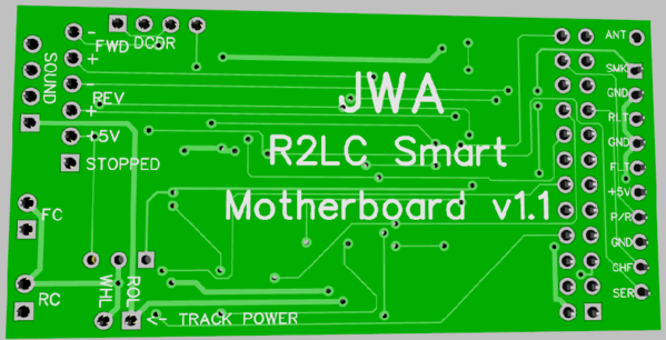
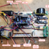
**** EDIT ****  Attached all the finished files to this post and updated the description to match the finished board.

I've started a new project to have a more functional way to do dummy locomotives with TMCC capability. It is also capable of being used in powered locomotives to add some features not commonly available with TMCC.

I have created a custom motherboard that will offer the following features.

  • Smoke & Directional Lighting Outputs
  • Electrocoupler Outputs
  • ERR Compatible Sound board Interface (4-pin JST-EH connector)
  • Logic outputs to indicate motion, forward, reverse, or stopped.
  • Separate 5VDC output for extra external functions
  • Buffered serial data to avoid data loading problems on the serial data line
  • Optional powered option with DCDR PWM outputs
  • DCS compatibility, will not interfere with DCS locomotives
  • TVS protection diode to protect the electronics

The motion logic outputs for forward and reverse indication are 100% optically isolated so you can use then in a wide variety of ways.  The opto isolators have diodes for DC reverse current blocking, and will sink at least 50 milliamps.

The 5VDC supply allows you to power external logic to do a unique task without having to provide a separate power supply.    It's possible to use the venerable LM7805T (or similar) to provide the 5V power.  The board is also sized for the Recom R-78E5.0 switching regulator module for higher output currents.  The switcher is obviously more expensive than the three terminal regulator, so unless you need it, the regulator is the cost effective choice.  If you plan on using more than 30-40 milliamps of +5VDC, then you need to add a heatsink to the LM7805T regulator.  If you opt for the Recom R-78E5.0 switching regulator, you have several hundred milliamps of +5VDC power available.

Some might question the odd placement of the components and why so much blank space.  It was planned, the blank sections are where the R2LC has tall components that typically sit right on the motherboard unless you have tall posts.  Since I didn't want to make the package any larger than it needed to be, I just put my logic in places there is clearance from the shorter components.  The white line down the middle is where the end of the R2LC board falls in case you wonder what it was for.

After measuring the R2LC & R4LC boards, I established keep-out zones for any parts as those the the tallest parts on the R2LC/R4LC.  In the other locations, there is room for the low profile SMT parts without any conflicts.  I also moved the one connector to the end by the R2LC connector, this makes it easier to route the heavier traces for the power and smoke functions.  The board is 1.25" x 2.5".  The power connection is a unique type of connector so you can't inadvertently connect the track power to one of the coupler outputs.

R2LC Smart Motherboard v1.1 3D T

R2LC Smart Motherboard v1.1 3D B

Build Files for R2LC Smart Motherboard

R2LC Smart Motherboard v1.1 Gerber.zip

R2LC Smart Motherboard v1.1 Schematic.pdf

R2LC Smart Motherboard v1.1 Assembly Diagram.pdf

R2LC Smart Motherboard v1.1 BOM.pdf

Attachments

Last edited by gunrunnerjohn
Original Post

Replies sorted oldest to newest

Net yet, I just wanted to toss the initial design out to see if it resonated or folks told me I was crazy.

I did think of adding another connector for the PWM motor outputs, that would make this useful for powered units and give you some added functionality. 

I may also add a buffer to the serial data as adding serial stuff sometimes overloads the serial line.  I'm thinking an op-amp circuit with a 2x gain to give me a nice 5V rail-to-rail serial data stream with more oomph so that it'll drive multiple inputs.

Well, the motor outputs are just the PWM signals from the R2LC, I'm not suggesting I'd add motor drivers!  I have wired a few diesels with a simple motherboard and the Cruise Commander M board.  The reasoning is that the CC-M has ditch light outputs, so I can have fully functional ditch lights.  With the addition of one 4-pin connector, I cover that base.

Well, the motor outputs are just the PWM signals from the R2LC, I'm not suggesting I'd add motor drivers!  I have wired a few diesels with a simple motherboard and the Cruise Commander M board.  The reasoning is that the CC-M has ditch light outputs, so I can have fully functional ditch lights.  With the addition of one 4-pin connector, I cover that base.

I miss read. I thought you were adding motor drivers as well. 

I was thinking about the 5V output.  I think I'll do a little rearranging and give room for a little switching module, the one I use on the Super-Chuffer.  It has the same pinout as the LM7805T, just needs slightly more room on the board.  Of course, if you're drawing more current, another consideration is making the filter caps more robust, that's another limiting factor.

I thought about the design overnight, and I realize that I will have to shuffle some things around, but I'll keep the capability the same.  I do want to buffer the serial data as I've had issues in the past overloading the R2LC output data line.

It's still a "work in progress", but I've been thinking about this for some time.  I know there are tons of R2LC's wasting away in various parts boxes, and this is a cheap way of reviving them.  I also thought about the current requirements for stuff like smoke, and I'm going to rearrange things a bit to make it easier to route stuff with heavier traces.

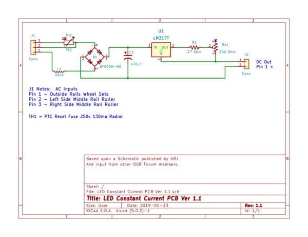
If you don’t already have them on this board, would adding a TVS diode to the board for protection against voltage spikes and adding a PTC to the board to protect against derailments where the rollers are shorted (one roller on center rail & other roller on an outside rail) be worthwhile?  The PTC would mean using a three position connector rather than the two position shown along with modifications to the board traces.

Yep, I do that a lot for passenger cars because the wiring they use in many of them is very small.  If you're using the typical 22ga wire for an engine or dummy, I don't see adding to the PTC for that.  Besides, one of the issues in bringing the current through the PCB is the potential for cooking traces on the PCB.

OTOH, I could see possibly having a PTC in the power lead that protects the PCB.  If the user wants to protect his wiring, he can add his own PTC.

Last edited by gunrunnerjohn

I bet folks with four motor AA PS1 locos or dead PS2 5V boards driving a slave board and four motors in MTH four motor AA units would go for a motherboard with plugs for two DCDRs to replace what ever was in their MTH 4 motor locos.   I was adding 15A triacs and a better heat sink  to TAS cruise boards but have used my stash and not found any lately.          j

@Jim Sandman posted:

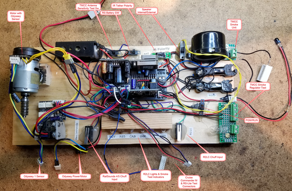
Useful to have one sitting around to test R2/R2LC boards if you don't already have a test setup.

Got that covered Jim.   I started with a simple motherboard, and I keep adding stuff as new situations come up.  I can test virtually all the TMCC and many modular Legacy boards on this rig now.  My only regret is if I knew it was going to grow like this, I'd have probably planned the layout a bit better.

JWA TMCC Test Fixture

@JohnActon posted:

I bet folks with four motor AA PS1 locos or dead PS2 5V boards driving a slave board and four motors in MTH four motor AA units would go for a motherboard with plugs for two DCDRs to replace what ever was in their MTH 4 motor locos.   I was adding 15A triacs and a better heat sink  to TAS cruise boards but have used my stash and not found any lately.          j

I'm pretty sure to drive two DCDR, DCDS, or CC-M boards, you'd want to buffer the PWM outputs.  They feed opto-isolators, and the load of two of them is likely to cause issues with the amplitude of the R2LC outputs.

Attachments

Images (2)
  • mceclip0
  • JWA TMCC Test Fixture

I haven't gotten the boards back yet, they're supposed to be on their way for Monday.  It did get to test the serial data buffer/amp circuit as I did a little PCB with just that on it. 

My first attempt at serial data buffering with a 2x amplification was a bust, it didn't work at all!  Then I looked closer.  Turns out the Microchip op-amp I was using had a dizzying array of different pinouts for their part, even with the same footprint!  I happened to pick one pinout for the board layout, but another one for the actual part!  I truthfully still couldn't figure exactly which package ordering option was supposed to be the pinout I was using from the datasheet.  Since I had a TI part with the same footprint and without the confusing multiple pinouts, I used that.  It worked perfectly and did exactly what I expected.  Very annoying that the Microchip part was so obtuse in their datasheet!   That being said, I'll be using the TI part in both the MB and my separate serial port buffer.

Monday I'll have the motherboard, and I have a project on my bench that needs two of them, so that will use up two of the three I ordered.

I just got a prototype sound board with a new interface I'm trying, but I'm still waiting on chips.  I am going to finalize it and have a quantity assembled as I think sound boards are in demand.  This is a 1.9" x 1.2" board that used a canned MP3 sound board and has five optically isolated inputs for five sound clips.  It also will offer an option to plug in a 4-channel RF receiver for remove control of the sounds.  The MP3 module plugs into the two headers on the right, the RF receiver on the bottom left.  I'll have more to say when I get the chips and can do a test. 

Attachments

Images (1)
  • mceclip0

I was looking at my motherboard and thought, gosh it would be cool to have the ability to have the "motion" output indicate stopped instead of motion.  Turns out, that was easier than I thought.  I can just swap the XOR gate for a NOR gate and it inverts the sense of that output.  Now it's useful for automatic control of a cab light.  If you want an indication of motion in either direction, you just tie the two "forward" and "reverse" outputs together, they're open drain FET's, so that works great.

I haven't put it together yet, just got the three boards.  I happen to have a project in-house that I need two motherboards for a couple of dummy locos, so I'm going to assemble just what I need on those and ship it out.  The third one will get the whole chip complement when I get my Digikey order later this week and I'll give it a test.  I think I'll wire up a little test harness with some bulbs so I can exercise all the functions.  If that test works out, I'll do a final "look around" and make any tweaks and then order a larger quantity of boards from one of the volume board makers.  Paying $5/ea from OSHPark ain't gonna' do it, I'd rather pay 60 cents each.

Add Reply

Post

OGR Publishing, Inc., 1310 Eastside Centre Ct, Suite 6, Mountain Home, AR 72653
800-980-OGRR (6477)
www.ogaugerr.com

×
×
×
×
Link copied to your clipboard.
×
×