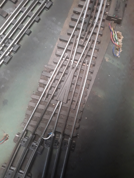
I am trying to wire in the derailing function on my Dz2500 switch machine with a Ross switch. I have got the machine itself working great but cannot figure out, even after reading the instructions how to connect the wiring to create the non derailing function? I have soldered a wire to each inside Crail which will be insulated. Where do the wires go from here I noticed there is a green and yellow wire coming out of the machine but can you please tell me how to wire it from here. Again, I cannot understand the instructions. I have no problems at all with my DZ 1000 machines.

Thanks for all the help as usual, Jerry 


Original Post

Replies sorted oldest to newest

It is as easy as @wmcwood posted earlier. Just to add, make sure the "isolated rail sections" are truly isolated from ground.

One other point, for derail feature to work, the power source for the DZ2500 must  have a common ground with the power source for the track. In other words, if transformer A is supplying voltage to the DZ2500 switch machine, and transformer B is supplying power to the track, then the common of transformer A (U terminal) needs to be connected to the common of transformer B (U terminal). Because of this common/U interconnection, the transformers have to be in phase.

Much thanks guys for all the replies. In response to one of your blogs I am using a common ground that goes around my whole layout and it is used for virtually everything.

I'm not sure with frogs mean?

I am sending some pictures of my switch and maybe you can help me figure out if it is isolated correctly? Or whatever if somebody has nothing to do and would like to contact me my phone number is 734-453-1809.

Jerry 20190106_16531520190106_16520420190106_165149


Attachments

Images (3)
  • 20190106_165315
  • 20190106_165204
  • 20190106_165149
Jerry A posted:

Much thanks guys for all the replies. In response to one of your blogs I am using a common ground that goes around my whole layout and it is used for virtually everything.

I'm not sure with frogs mean?

I am sending some pictures of my switch and maybe you can help me figure out if it is isolated correctly? Or whatever if somebody has nothing to do and would like to contact me my phone number is 734-453-1809.

Jerry 20190106_16531520190106_16520420190106_165149


From the pictures it looks like you have a connecting wire going from the two inside rails after the frog. That wire needs to go. Instead a gap needs to be cut in each rail,this can be where they are joined with the Lionel style track. The green and yellow wire are connected to these two now insulated rails.

wmcwood posted:

switch

I assume you have insulated pins between switch and lionel track.  The white wire needs to go to the green DZ wire and blue DZ wire to other isolated rail.

It looks like the RT or diverging isolated rail may be touching the Lionel track piece.


You mean yellow wire, not blue. Blue wire is for control by tmcc is it not (data wire).

Last edited by ehkempf

I do have insulated pins on both inner switch  track rails to the Lionel track .

So you are saying I take the blue wire soldered to the switch and connected to the green wire on the DZ  then I take the green wire DZ and physically do what with it as I am not sure what you mean by taking it to an insulated rail.

Before I took the blue  and white wires soldered to the track and connected them to the green and yellow DC wires then I connected each one  to ground that goes around my track and all I got was chatter.

Once I get this down correct I will be okay and thank you very much for the help. I am still lost.

Do not use the blue wire. It is the data wire and is only used for tmcc control of the switch machine. The two wires used for non derailing are the green and yellow. You need to isolate the two rails that come out of the frog. You can do this with isolating pins or by cutting the rail. The diagram clearly shows this step. The green and yellow wire are connected to the isolated rails, green to one yellow to the other, again the diagram shows this.

My white wire is only soldered to one  inter rail. The blue wire is soldered to the other inner rail. Please give me a blow-by-blow description what to do with the wires. I would like to know what to do with each wire if you can do that I think I will be home free.

I assume oh, I still have to cut notches in the inner rail of each side to create an open circuit.

I'm trying not to make a habit of asking stupid questions but my DZ 1000 machines were so much easier to wire derailing. Again, once I understand how to do it I think I will be okay.

Thank you very much, Jerry


As have been previously stated above, combining several of the posts, you need three things to make the DZ2500 derail feature work.

First -  common ground between the track power source and the DZ2500 power source. You have written that you have already accomplished this.

Second - the isolated rail sections. I am pretty confident that with the Ross Switch, and the fibre pins you installed between the tubular track rail and the switch track rail you show in your picture, you should have the isolated rail sections handled. You can verify if they are truly isolated, but I will write about how a bit later.

Third - connecting the green and yellow wires from the DZ2500 switch machine to the isolated sections of rail. Green of the DZ2500 to the turn out isolated rail, Yellow of the DZ2500 to the straight thru isolated rail.

Like activation for some accessories using the isolated rail technique, the concept is that the wheels/axle complete the ground connection from the non-isolated rail to the isolated rail section.

To determine if you have isolated the rail sections, I would disconnect the DZ2500 green and yellow wires from your isolated rail sections, but you can leave the wires you have already connected to the rail sections in place, just let them hang in the air. The best method to me is to use a Volt Ohm Meter to measure ohms. For this method, the power should be off to the track and DZ2500. With the meter set to measure ohms, just keep the two leads separated in the air, and see what your particular meter shows for an open circuit. Then touch the ends of the meter together, and see what you meter show for a short circuit (should read 0). Touch one meter lead to the isolated rail section, and the other lead to an outside rail you know is not isolated. If you have the isolated rail created successfully, the meter will show the reading for an open circuit. If not, the meter will most likely show 0, or close to it.

If you don't have a meter, an idea I have is to use an accessory that has a light bulb in it. Again, have the DZ2500 disconnected from the isolated rail sections. Apply track power. Touch one lead from the accessory to the center rail, and the other lead from the accessory to a non-isolated rail, and the light should come on. Now, keeping one lead on the center rail, touch the other lead to the isolated rail section, and the light should not come on, thus indicating ground is not present, the rail isolation actually exists.

Once you have convinced yourself the isolated rail sections exist, connect the DZ2500 switch machine Green and Yellow wires correctly for thru and out to your wires previously soldered to the isolated rail sections. Turn on all the power, have a car on the track you can move with you hand outside of an isolated rail section, use the button on top of the DZ2500 to put the switch in the opposite position from where the car is, then push the car into the isolated rail area, and the DZ2500 should change to the correct state.

Add Reply

Post

OGR Publishing, Inc., 1310 Eastside Centre Ct, Suite 6, Mountain Home, AR 72653
800-980-OGRR (6477)
www.ogaugerr.com

×
×
×
×
Link copied to your clipboard.
×
×