Good Evening,

So I just expanded my current layout and added remote / command switches.  I am having issue with voltage drop in two areas on the layout.  The voltage on my layout is 19-19.2 volts with the exception for the three highlighted areas, where my fluke reads less than 1 volt.  I am wondering if I need more power connection for the layout or if this is human error.  I have taken the track apart and bent the tabs inwards to make the track connection tighter.   I would appreciate all advice, help, or criticism.  The red circles are the power supplies to the track, while the blue circles are the problem areas where my locomotives stall right out at. 

Thank you so much-

Attachments

Images (1)
  • needhelp
Original Post

Replies sorted oldest to newest

I run 12g on most of my busses as well. Even on a small layout I run my bus & it's fuse based on max transformer output + some overkill on gauge (not fuse, the fuse/breaker should match expeted draws vs the max, I.e. max or a lower amp fuse if possible). I don't choose for what I expect to use, but what power might flow in a worst case scenerio. I hate melted insulation/looms and the overkill helps prevent it in near bullet proof ways.    To me it is worth the extra cost for a little more copper in an open air situation on wood too.

The distance between drops isn't an issue of how big a layout is. It applies to a 4x8 or 40x80.  It's about resistance over x number of joints and x length of rail.  Wire carries electrical that much easier than rail. 

Drops can be smaller gauge because of shorter lengths added up with rail yeilding a larger capacity as a whole.

Standards for wire are a mininum for "safe" production; mininum.

Overkill in gauge doesn't have negative model RR effect until you pretty deep into some thing with frequencies in sound or controls, etc. (e.g. some freq. can get "lost" or cut off by gauge size and strand counts. Look at a good surround sound system, thin wire on surround speakers, larger stranded on mains, even larger feeds for driving subwoofer system, all based on power max & strand counts for accurate frenquency delivery.  )

Along the lines of better electrical paths, dont count on turnouts to deliver power though itself to the other tracks attached.

Jump the power around the turnout.

I.e. one feed on on the entrance side, and one on each exit, for 3 total drops for 1 turnout (5 for two switches if they are close and share an approch; it still puts 3 near each).

In tubular days Lionel also put this in some literature as the "best way" if that gains your confidence. 

The traces inside switches aren't huge; that's a "wire gauge". Plus moving contacts and coil draw can have less impact on the engine with a heavy draw too simply by adding better paths to distribute it all with.

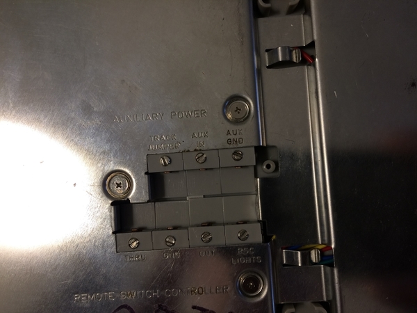
WRT Fastrack track switches, if they are remote control I run a ground wire from the layout track power buss to the "AUX GND" terminal on the switch and a hot wire to the "TRACK JUMPER" terminal on the switch. This feeds power directly to the rails like any drop. Of course I also run a wire from the layout accessory power buss to the "AUX IN" terminal on the switch to power the switch motor.

Lew

                IMG_2882

Attachments

Images (1)
  • IMG_2882

FWIW, if you're putting Fastrack down permanently, I recommend opening up all the switches and soldering any tabs that have active connections inside the switch.  Lionel, in a truly questionable build practice, counts on simple folded tin tabs for continuity inside the switch.  This is the problem that plagued standard tubular switches as well, and the same fix applies to them, solder all the affected connections inside the switch.

What are the dimensions of this layout. I presume the dots are 12" apart? So your like 40'x12' If so indeed you need more feeders.

I've had great luck with 14 ga  stranded wire soldered directly to the power tabs underneath the fastrack with feeders every 10'. No voltage drops anywhere.

Soldering to fastrack is easy, and it only takes a couple  of seconds with an inexpensive Weller 25w iron. No fancy expensive high powered gun required.

Need to change something, a few seconds on the solder with a hot iron will release the wire.

My modest 12'x16'  fastrack layout just turned 14 years old. I've never experienced the voltage loss issues that come up from time to time. Even after part of the track got wet (don't ask) dried it out and buisness as usual.

 You didn't mention what size wire your are using but the puny 18ga  starter set stuff with those tiny slip on connectors ain't gonna cut it.

I  also see a fair amount of uneven trackwork with big gaps on this forum. Its no wonder some folks have issues.

I've gone so far as to shim uneven areas of track with index cards, after looking down the long end of straight sections to find the dips, this is especially important for turnouts.


Thank you so much for everyone's help.  So in response to everyone's help, I have some things to change.  For starters, I am using 16 AWG wire and only have three power connections to the track.  Over the weekend, I will change out the wire to 12 AWG and add many more sections so the track is connected every ten feet.  In addition, I am also going to wire each switch with its own power supply.  Hopefully, that should help.  I will report back once I make all these changes.  As always, thanks for everyone's input.

A few things not already discussed:

1) I found that each TIU channel can handle about 10 wire drops to the track. More than that caused me signal issues. I am not sure of the cause, however too many feeds off the same channel was an issue for my layout. I feed a pair of wires from the TIU to a terminal strip, then from the terminal strip to the various track connections in that area of the layout. This keeps the wire length to a minimum. I also cut the center rail (which you can do by removing the connecting wire for the center rail located under the fastrack short track pieces. These pieces are on all but the O36 switches). This keeps the TIU signal from "bouncing" back off the next track section. I was told this would improve the TIU signal quality.

If you use the switch center rail jumpers to "break" the center rail, you will need about 8 or 9 connections for your layout.

2) I found that I could have about 10 track joins on each side of the track feed wire. 

3) some of my shorter sidings are fed through the switch and work fine.

4) I have my switches running off a separate auxiliary transformer at about 16VAC. To do this, you need to remove the jumper on the bottom of the switch. This change improved my signal strength, as the switches would sometimes degrade the TIU signal quality.

Good Luck with improving your signal strength.

I want to thank every person who went out of their way to help me with my issue.  I finally got around to reading/testing all of everyone's suggestions, and all the advice paid off.  My new layout is up and running.  I added a bunch more drop points and cleaned up my electrical distribution from my TIU.   

You guys are awesome!!!!

Add Reply

Post

OGR Publishing, Inc., 1310 Eastside Centre Ct, Suite 6, Mountain Home, AR 72653
800-980-OGRR (6477)
www.ogaugerr.com

×
×
×
×
Link copied to your clipboard.
×
×