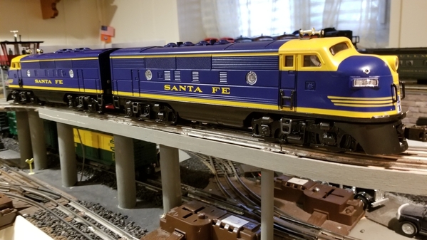
And this will be the last time I buy used ERR boards....
@gunrunnerjohn posted:Really odd, that board was only made for the C420 engine so that the marker LED's would work without swapping wires, apparently they did those for that production run after they were wired wrong.
Boy, aint this just my lucky day.
Gonna play Powerball now....😂😂😂
Just remember, all those little pearls of knowledge are typically hard-won, just like this one for you. ![]()
![]()
@RSJB18 posted:
Its always something!
I guess it says well for me since I lived through 43 years of electronics. Though I did cause a few sparks and got zapped with 125 volts dc a couple times 😫
@gunrunnerjohn posted:Just remember, all those little pearls of knowledge are typically hard-won, just like this one for you.
They sure are John.... where's my single malt? 🥃🥃
@Mark Boyce posted:Its always something!
I guess it says well for me since I lived through 43 years of electronics. Though I did cause a few sparks and got zapped with 125 volts dc a couple times 😫
Been zapped many times over the years Mark. 277 vac was bad, but 50vdc really hurt....
@RSJB18 posted:They sure are John.... where's my single malt? 🥃🥃
Been zapped many times over the years Mark. 277 vac was bad, but 50vdc really hurt....
I didn’t even mention ac. DC is much worse! 🤯
And we have working markers..... ![]()
A huge thank you to @gunrunnerjohn for his help and patience, along with some skilled detective work.
Bob
Attachments
@RSJB18 posted:And we have working markers.....
A huge thank you to @gunrunnerjohn for his help and patience, along with some skilled detective work.
Bob
Bob, that is awesome, project well done even with the gremlins! ERR F3/7 sound board, I know it well, and it sounds great in your SF F3! Thanks for sharing that project with us. GRJ is awesome, helped me more than once!!!
Excellent project! Well done, Bob!
Ver well done BOB!!!👍👍 Have fun with that engine.
@Mark Boycee @laz1957 @WesternPacific2217
Thanks guys.
I need to relocate the wires inside the shell. The front motor hits them on a turn, but that's easy compared to the lighting issue.
Now on to the trailing A unit and how to connect it to the lead A. ![]()
Bob
I hope yours turns out as well too, Carl.
I'll be adding the ERR to an MTH PS1, so it will be a little different (I hope easier) than Bob's. I did learn to buy new ERR boards and which end is cathode and which is anode on the diodes. ![]() I'm afraid what I learned over 45 years ago didn't stick.
I'm afraid what I learned over 45 years ago didn't stick.
@Pingman posted:
, @RSJB18,
Turned out GREAT!!! Well worth your efforts. Hope mine will turn out as well.
Thanks Carl- despite the frustrations with the LED's, it's been a fun project so far.
@Mark Boyce posted:I hope yours turns out as well too, Carl.
I'll be adding the ERR to an MTH PS1, so it will be a little different (I hope easier) than Bob's. I did learn to buy new ERR boards and which end is cathode and which is anode on the diodes.
I'm afraid what I learned over 45 years ago didn't stick.
I have a few PS-1's that I want to upgrade eventually too.
Bob
@RSJB18 posted:
![]() BINGO
BINGO
Now that I have the great marker light saga behind me, it's time to move on to the lighting in the trailing "A" unit.
This required adding a harness between the engines and of course, more wires.......
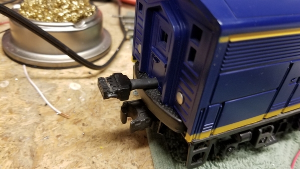
I'm using an MTH 10 pin harness* that I have installed in the base of the door on the back of the lead engine. I didn't want to cut the shell but there was no other option so some minor surgery was required. The plug is glued in with JB weld. I didn't realize until after the epoxy dried, that it found it's way into the base of the plug, fouling the pins. I was able to clean it up with my Dremel and a very small milling bit that I have.
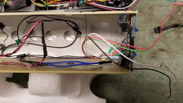
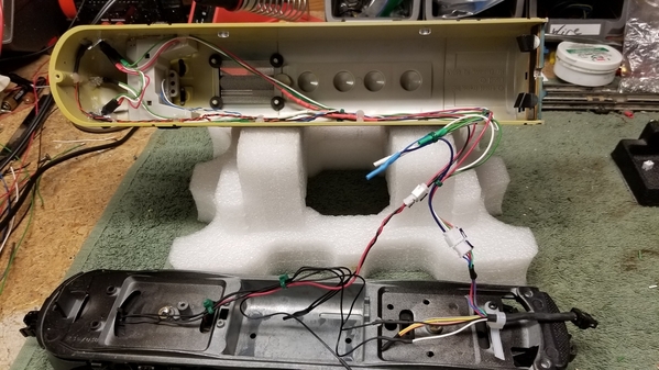
I need 6 wires between the units- head light and green markers, red markers, 2 for the cab light, and two for the coil coupler. I was debating how to connect the second set of lighting wires but settled on adding them right off the board which actually worked out well. I see now why John is designing the new board for the R2LC's. A whole lot less work.
I will add another set of JST plugs so that the lead shell will still be completely removable. The two blue wires with the single plugs are for the rear coupler.
Progress pix.....
Bob
* harness part-
TETHER / STEAM / 10-POSITION / 90 DEG CONN. / UNIVERSAL PS 2 , LOCOSOUND AND PS 3 STEAM UPGRADE KIT SKU: BC1000002 |
Attachments
@RSJB18 posted:The plug is glued in with JB weld. I didn't realize until after the epoxy dried, that it found it's way into the base of the plug, fouling the pins. I was able to clean it up with my Dremel and a very small milling bit that I have.I need 6 wires between the units- head light and green markers, red markers, 2 for the cab light, and two for the coil coupler. I was debating how to connect the second set of lighting wires but settled on adding them right off the board which actually worked out well. I see now why John is designing the new board for the RL2C's. A whole lot less work.
Plain old clear tape will solve the problem of the JB-Weld going where it shouldn't. ![]()
FWIW, you probably used more wires than needed, all of the grounds can be combined into one wire.
I never solder to the R2LC directly unless there's no other way, that way I can replace it without using a soldering iron. ![]()
@gunrunnerjohn posted:Plain old clear tape will solve the problem of the JB-Weld going where it shouldn't.
FWIW, you probably used more wires than needed, all of the grounds can be combined into one wire.
I never solder to the R2LC directly unless there's no other way, that way I can replace it without using a soldering iron.
John- Yea- tape would have helped. I didn't think the epoxy would be that runny.
I thought the cab light had to go back to the board? (I'm using the smoke output). The rest will go to the chassis in the trailing unit.
I was referring to the new terminal board you discussed recently to add a second R2LC to a trailing unit as a "second" engine in a MU'd set up.
More lessons learned......![]()
All of the lighting outputs and the smoke output are common to frame ground for TMCC. The coupler outputs are also common to frame ground. Four wires would do the whole trick there, a ground and front, rear lights, and coupler.
I've been working on my F3 dummy unit today. I finished up all of the lighting and will install them in the shell next.
The cab interior is done and the relief crew has reported for duty. I used the Lionel figures for this one.
Rear coil coupler installed and power and common wires are ready to go.
I'm also working out how the tether will connect between the engines. Since there is very little room between the two, I'm going to let it slide in and out of the dummy and plug straight into the lead A. I cut a small slot in the base of the shell to make room for the harness. I will fabricate some sort of strain relief to hold it in place to prevent the wires from getting pulled out if the two engines should separate accidentally.
to be continued.......
Bob
Attachments
@gunrunnerjohn posted:All of the lighting outputs and the smoke output are common to frame ground for TMCC. The coupler outputs are also common to frame ground. Four wires would do the whole trick there, a ground and front, rear lights, and coupler.
Yea- I wasn't sure if I could do it that way John. The wiring diagram from ERR shows the commons going back to the board so I went that route.
If you add this dummy locomotive board, you don't need any wires between them, a much neater install. ![]() Just add an R2LC and you're golden.
Just add an R2LC and you're golden.
FS: Dummy Locomotive PCB kits for TMCC Control

Attachments
@gunrunnerjohn posted:If you add this dummy locomotive board, you don't need any wires between them, a much neater install.
Just add an R2LC and you're golden.
FS: Dummy Locomotive PCB kits for TMCC Control
Next A-A or A-B I do for sure......
I've been chipping away at the dummy wiring as time permits over the past few weeks. I can finally say that both engines are back together and have been tested. New problem popped up....more on that in a few.
I finished the harness between the locos and terminated all of the wires in JST plugs. Both shells can be removed completely from the frames for future service. All of the lighting has been tested and works as it should. Both coil couplers do as well. I still need to black out the back of the LED's on the dummy shell which will be obvious in the video below.
So the new problem was one I kind of feared/ expected as I was building. The engines are close together, so on my 027 curves the MTH harness doesn't have the flexibility to remain connected. This will require a do over but not an insurmountable obstacle. I have something in mind and will make short work of the change once I get the parts in hand.
Still happy with the work to date. This project has been a learning experience that will be applied to future upgrades ![]() .....and I have a list.......
.....and I have a list.......![]()
Here's a video of the lighting on the trailing A unit.
A big shout out and thank you to John @gunrunnerjohn for all of his advice and guidance and "pearls of knowledge" along my journey.
Thanks John!
I'm a happy O-Gauger so I will Keep Calm and Model On!
Bob
Attachments
@RSJB18 posted:I've been chipping away at the dummy wiring as time permits over the past few weeks. I can finally say that both engines are back together and have been tested. New problem popped up....more on that in a few.
I finished the harness between the locos and terminated all of the wires in JST plugs. Both shells can be removed completely from the frames for future service. All of the lighting has been tested and works as it should. Both coil couplers do as well. I still need to black out the back of the LED's on the dummy shell which will be obvious in the video below.
So the new problem was one I kind of feared/ expected as I was building. The engines are close together, so on my 027 curves the MTH harness doesn't have the flexibility to remain connected. This will require a do over but not an insurmountable obstacle. I have something in mind and will make short work of the change once I get the parts in hand.
Still happy with the work to date. This project has been a learning experience that will be applied to future upgrades
.....and I have a list.......
Here's a video of the lighting on the trailing A unit.
A big shout out and thank you to John @gunrunnerjohn for all of his advice and guidance and "pearls of knowledge" along my journey.
Thanks John!
I'm a happy O-Gauger so I will Keep Calm and Model On!
Bob
Looking good Bob, the light is at the end of the tunnel! Oh darn about the tether! Really impressive upgrades! I agree, gunrunnerjohn is great, and so are his products.
@RSJB18 posted:Still happy with the work to date. This project has been a learning experience that will be applied to future upgrades
.....and I have a list.......
I'm a happy O-Gauger so I will Keep Calm and Model On!
Bob
Congrats on a successful upgrade, Bob… you are a braver man than I ![]()
![]()
As Ko-Ko was heard to sing: “As someday it may happen that a victim must be found, I’ve got a little list… I’ve got a little list” ![]()
![]()
Looking good, Bob! The tether issue will be easy as you already know what parts you want.
I guess we should have mentioned the flexibility of the tether, that's a key component. ![]()
@gunrunnerjohn posted:I guess we should have mentioned the flexibility of the tether, that's a key component.
Yep. I have another one with a right angle plug but it won't fit. Since I don't need the commons from the lead engine, I'm going to use a 4-pin micro connector from Miniatronics. I've used these on other engines and they are well made. If you have any other suggestions, let me know.

@WesternPacific2217 @Apples55 @Mark Boyce
Thanks guys. At least it's off my work bench for a while. I plan to run the powered unit until the plugs arrive.
Bob
@Pingman posted:@RSJB18, with your terrific project and one brief op session with my recently purchased TMCC F-3s, I'm going to swap out the chassis/horizontal twin motors of my PW F-3AB GM&O diesels.
I had considered replacing the pullmor's with can motors Carl but with all I was putting into them for the controls, I decided to keep them. It helped that they were like new with very little run time.
I saw your post on the new ABA set, looks sharp!
Bob
Nice work!
@Darrell posted:Nice work!
Thanks. I'm afraid I'm heading down a very slippery (and expensive) slope.......![]()
Bob
@RSJB18 posted:Thanks. I'm afraid I'm heading down a very slippery (and expensive) slope.......
Bob
I was thinking that myself. ![]() Do I want to start down that road as well?
Do I want to start down that road as well? ![]()
Shoot the dice guys, besides we need a new crop of repair guys, so we have to break someone in. ![]()
![]()
@Mark Boyce posted:I was thinking that myself.
Do I want to start down that road as well?
Jump on in Mark. The water's fine !
@gunrunnerjohn posted:Shoot the dice guys, besides we need a new crop of repair guys, so we have to break someone in.
Don't think I'm there yet John. Maybe some day.....
Bob
Bob, I haven't even purchased the ERR parts yet for the F3 AA yet.
Welcome to the poorer by the month club, at least GRJ has the units for a decent price. I am at 19 commanders, all but 3 CC, and working on my first personal 4-8-4 conversion using his SC CG.
As I tell my wife, I could be cruising the bars for a lot more money spent.
@Ron_S posted:As I tell my wife, I could be cruising the bars for a lot more money spent.
And nothing but a headache and AA meetings to show for it! ![]()
![]()
John,
In my younger days, closing the bar was normal, heading to after parties often, then going on duty and power napping after, unless I flew the next day.
I wised up about 28 and started spending time on healthy things, like motorcycles, wars and trains. Now that I am well seasoned, a fun day has TMCC, DCS and throttles in it, as well as classic cars, good coffee, wine and a decent scotch at the end of the day in moderation.
I never thought I would see 50, let alone 60 and now I am staring 70 in the face. And I still can't handle those darn SMT diodes and resistors, even using the HD microscope.


