I have a TIU Rev L that needs repair. It seems that the Fixed Voltage 1 function that communicates with the engines has failed. It communicates fine with the WiFi unit/smartphone and with the old hand held remote, but is unable to find or add any engines. The track power is fine. I have tried resetting the TIU and the old remote to no avail.

I did some work on it to see if it was a component I could replace. I found that the 3 pin 5 V regulator (7805) (U363?) was very hot and the output was not at 5V (I think it was around 3 V) so I replaced that. After replacement, the output was 5V but it was still getting hot and still not communicating with the engine. So I shut it back off. My guess is that there is a short or failed component that is drawing excessive 5V current, and that is what burned out the original 7805 5V regulator.

Prior to the failure of the TIU, I had some problems fuse 554/555  blowing, but I think that might have been a mistake in how I had the power inputs hooked up.

I also noticed that the 5 pin voltage regulator(LM2577, U240) is getting warm, but the voltages coming out of that seem to match those of the other TIU that I have which is fully functional.

I did replace the FETs on this TIU a few months back when one of the variable power channels was not working. That resolved that problem.

I do have some of the power components on hand that I ordered previously and can order more it appropriate. But with no schematic I don't want to do anything more without some guidance. I am also OK sending it to an authorized MTH repair person if appropriate.

Thank you

Walter Bell

Original Post

Replies sorted oldest to newest

I recently repaired one that had a similar problem. It was all 4 of the DCS signal drivers. They are on the 5V rail and thus if they die and fail shorted, they load the 5V power bus down.

In a nutshell, do not power via aux power or channel 1 if you suspect a short like you have now. All you do is stress the power circuit. If it is a Rev L hardware TIU with a USB port, power only with a current limited USB source. Remove the suspected ACT244 chips one at a time and then power with USB. Eventually, with luck before removing all 4 you will get to a state where the TIU power is stable and the power LED indicates properly the TIU ID and the remote will talk to the TIU over the coil cord connection. Once you are at this state, then replace the ACT244 one at a time and test each time in between to ensure no errors or shorts.

Again, my impression is, you likely killed the ACT244 drivers with all the abuse and failures you put this through. Eventually they now have shorted the power supply and you instead of fixing the problem- began troubleshooting the power supply that was getting hot because it too was being abused.

Also, I'll give you a tip. As that photo is placed, the leftmost ACT244 is VAR1 channel, then the one right of that (the middle in the group of 3) is the fixed channel 1 driver, and then next right is fixed 2, and then the one kinda all by itself is var 2.

Since you were using fixed 1 at the time of failure, that is the first one I would remove and see if the power supply situation improves. Then remove the other ones in the order that you may have used channels or had failures. That way, you are hopefully starting at the one most likely to be the damaged one causing your power problem. Solve the problem- not the symptom.

I too suspected a power supply issue and burned the ever living fingerprint off of my finger on that regulator. I assumed the PSU failed, that let high voltage into the logic and just killed the TIU. However, with little to lose at that point, I didn't think that the ACT244s all could be shorted. Was I ever dead wrong about that. So now that I know about that possible and likely failure mode, if I see high current draw (on the logic 5V power), I then have to switch the way I power the setup using a powered USB hub that self limits a USB to no more than 500mA. Again, just saying, I did it too and a hard and painful lesson learned.

I have done more investigation. I lifted the Vcc pin of each of the 4 ACT244 and did a quick check for the high 5V current draw by using my finger as a heat sensor on the 7805 voltage regulator. Overcurrent condition remained. Then I removed the LM2577 5 pin voltage regulator and the high current condition stopped but the Power LED also did not light, so the 2577 must be required for that function. I replaced the 2577 with a new one and the high current condition returned. So I am guessing the cause of the high 5V current is somewhere downstream from the 2577.  I did a quick check on the 2577 and noted that the Vin was around 25V DC. Pin 4 (Switch) was also around 25 V. I don't know where to check for the regulated output or what components the 2577 powers.

Any suggestions on what to check next or an explanation of what the 2577 would be very helpful.

As always, guidance from the group is greatly appreciated! Getting this TIU fixed would be very valuable gived the shortage of TIU's and the continued delays of the new one from MTH.

2577 is a switch-mode voltage regulator IC that generates 12V DC.  The input to the 2577 regulator is AC/DC thru a bridge rectifier from Fixed1 or Aux Pwr (if used).  12V DC is sent to the AIU output and the 2 internal 12V DC relays on the fixed channels.  Downstream regulators like the 7805 convert the 12V DC to other useful voltages like 5V for the ACT244 buffers.  Note that AIU serial communications was done with 5V digital chips from day 1. The complex digital stuff like the microcontroller, memory, and top-secret DCS spread-spectrum communications processor chip run on 3V (3.3V) so you should see at least one other regulator chip as well.  Again, all these regulators are downstream from the 2577.

If as @Vernon Barry suggests you can power the digital stuff from the USB port, that suggests the 3V regulator is downstream from the 5V voltage.  That is, you need the processors running to get anything to happen at all.  If using this method for troubleshooting, you will not have 12V DC to power an AIU or the fixed channel relays but who cares if troubleshooting the ACT244's!

Thank you for this clear and thorough overview of the power system. With that knowledge, I was able to locate the 3V regulator and quickly check that it was operating properly with no overheating. So the cause of the excessive 5V current seems to be in some part of the TIU that is running directly on 5V. As I mentioned earlier, I tried unsoldering and lifting the Vcc 5V power pin sequentially on the ACT244s rather than unsoldering the whole 20 pin surface mount chip, but the overcurrent remained. Am I correct in assuming that approach would test whether the excessive current draw is coming from a failed ACT244?

Thanks again for the tutorial; I am learning a lot from you all!

@Walter Bell posted:

... I tried unsoldering and lifting the Vcc 5V power pin sequentially on the ACT244s rather than unsoldering the whole 20 pin surface mount chip, but the overcurrent remained. Am I correct in assuming that approach would test whether the excessive current draw is coming from a failed ACT244?.

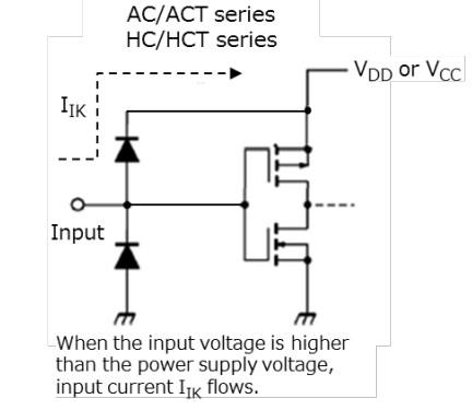
AC gate input protection

Maybe, maybe not.  Virtually all modern logic chips have input diodes that effectively allow any input pin to power the chip thru a klamp diode with klamping current as depicted in above diagram. One might correctly observe that this clamping current would be limited by the capability of the input signal which likely came from another digital chip with limited power.  But it is common practice to tie unused digital input pins directly to +5V or ground (rather than via a resistor).  I don't know if that's the case with the TIU ACT244's but is something to consider.

Like the guys say,  @GGG has a treasure trove of knowledge in troubleshooting/repairing TIUs.

But if you still have the time and interest for more DIY, I'd look at previous OGR discussions on failing ACT244s.  IIRC there are some over-voltage components to protect the ACT244 outputs from voltage spikes from the track.  Seems to me if one of those components failed-shorted, it could ask too much of the ACT244.  Just speculation though.

Attachments

Images (1)
  • AC gate input protection

Did you lift the receiver chip too?  I think it has been hit or miss removing a leg on a chip.  You have the 5V, the DC ground, and unknown other interactions.  Knowing how the TIU was being used at the time of the fault can sometimes help.  But remove chips completely.  Start F1.  But if all 4 transmit off and still short, remove receiver chip.

Frankly, I power up tiu with Z-4000 amp meter.  If I have high current, I know I have a short.  I DO NOT continue to run it with a short.  If all the transmit and receive chip bad, 3V ok, you have other chip damage that involves 4 sided kazillion leg chip that makes TIU unrepairable at our level.  G

Thanks for this informative and very helpful advice. I should have thought of monitoring the input AC current sooner; that's much quicker and easier on the power circuits than the finger method!

With that set up, I measured around 450 ma input current on the Fixed 1 input power line so around 8.5 watts input power. I removed the F1 ACT244 chip completely and the input power level was unchanged. Will keep going on removing the ACT244s one by one (F2 next). If that doesn't work I will remove the transmit chip as you suggested. Which one is that?

Thanks again so much to you and all the contributors for your patient and constructive advice.

Even if I am unable to save the TIU I have gained very valuable understanding of the TIU structure in this area, which I can use for the next issue.

Best regards to all,

Walter

Add Reply

Post
The DCS Forum is sponsored by

OGR Publishing, Inc., 1310 Eastside Centre Ct, Suite 6, Mountain Home, AR 72653
800-980-OGRR (6477)
www.ogaugerr.com

×
×
×
×
Link copied to your clipboard.
×
×