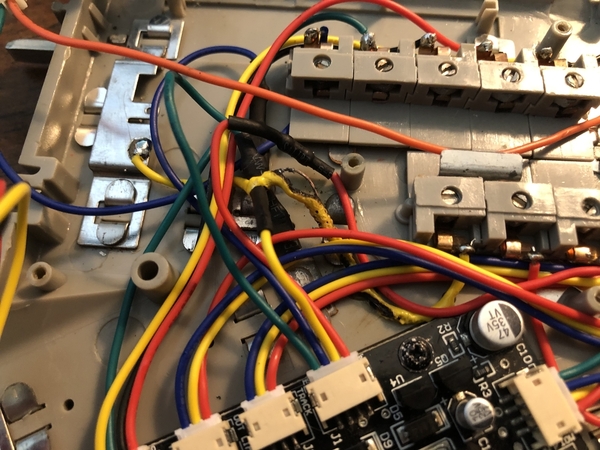
My 072 Fasttrack switch is not showing the indicator lit and only has power on the upstream side. The switch is going to a dead end siding that does not have power on both sides of the switch. I had an older switch in there with a manual remote controller but that was not able to be controlled with the Legacy handheld but it worked fine. So I put this one in (that does not have the manual remote controller on it but is controlled via the Legacy controller) from another location on the layout. Now there is only power on one side of it and no light etc. What am I missing?
Original Post