Does anyone know if the Fasttrack Switch Controller cable is available separately. I have several switches that are a long distance from my control panel and I want to find the color coded 4 wire cable to extend the existing factory cable.
Replies sorted oldest to newest
Use cat3 4 conductor phone wire to extend...may not be exact color match but the electricity doesn't care....
I just use phone wire, the two pair four wire one. The colors even match. Run the controller cable to a terminal block, then phone wire to the switch. I also use phone jack crimp on ends near the switch so I can remove a switch by just unplugging it, but that is not really necessary. It is a lot easier to disconnect wires at the switch than it is at the controller, so I leave the controller wire attached.
Sorry, Eddie. I was typing while you were posting.![]()
Thanks for the info guys, much appreciated.
George
Most of the phone cord I see in the big box stores is tan colored, which I am not fond of. If you're looking for black 4 conductor wire, try Amazon - this one is 300' , which may be more than you need (I had 18 switches to wire), but they also make a 100' roll (you can cut off the connectors). I also used "jelly bean" crimp connectors to connect to the FT wire and found them pretty easy to use.
https://www.amazon.com/Phone-C...+phone+wire+300+feet
I use vinyl covered 4 conductor wire, about 22 gauge. I run 4 feet of cable down under the layout and then in a connector strip, attach the 4 conductor cable. Then another strip I attach the original controller cable. I would recommend 5 or 6 conductor though so you have the option of auxiliary power instead of relying on track power.
I am reviving this ancient thread because of the possible need to connect Fastrack switches to ASC2's or STM2's. I couldn't find another thread that addressed the approach that I have taken.
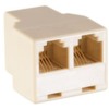
Many years ago when I built my layout (that I have now ripped up and am redesigning), like many others, I needed to extend the length of the remote cables for Fastrack switches. Since remote controls just use standard 4 conductor telephone wire, I bought a bunch of that wire. I also bought a bunch of RJ-11 plugs and 3-way female RJ-11 connectors.
I disconnect the cable from the switch and install an RJ-11 connector at the end of the cable. I install an RJ-11 connector on the phone wire that I purchased. The RJ-11 from remote cable and the RJ-11 from the phone cable plug into the 3-way RJ-11 connector. You can measure how much phone cable you need to reach the switch. Cut, strip and install the 4 conductors to the switch. This leaves you with a spare RJ-11 jack on the 3-way connector. Put an RJ-11 connector on another piece of phone wire and you can now connect the appropriate conductors to ASC2's and/or STM2's.
Be sure to ensure that you are wiring the RJ-11 plugs with the correct polarity. With 4 conductors it is easy to get them crossed through plugs and connectors.
Using the RJ-11's makes it easy to remove a switch for repair or to move it. If your switches are mounted to plywood, make sure the hole for the remote cable is large enough for the RJ-11 plug to fit through.....don't ask how I know this. ![]()
Attachments
I'll add that it is simple to substitute those miniature toggle switches (SPDT spring-loaded center-off) and a 2.5mm red/green LED for the OEM huge switch-controller thing.
Bi-color LEDs switch colors by reversing the polarity which is what the yellow wire does (the LEDs in the OEM control also are bi-color polarity reversing).
Makes for tiny unobtrusive "control panels" easily affixed to the front edge of the layout.
That black thing is an MTH DCS Remote Commander which is the only other control apparatus needed to operate the Plywood Empire Route.


