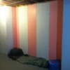
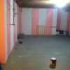
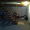
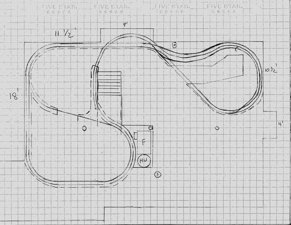
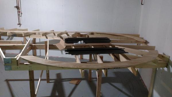
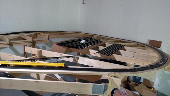
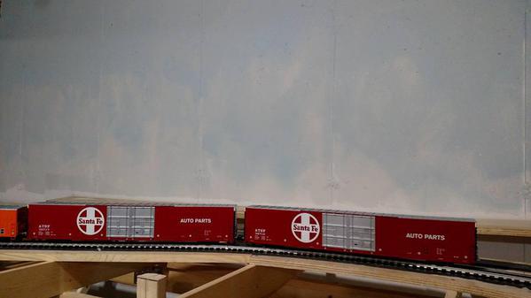
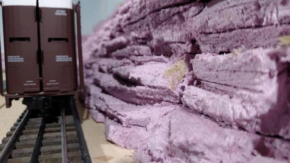
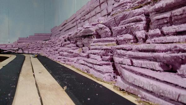
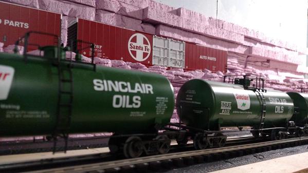
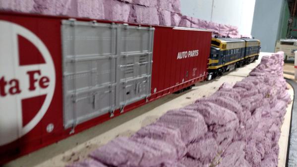
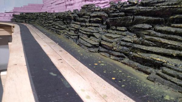
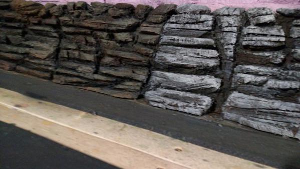
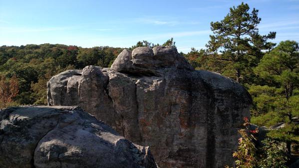
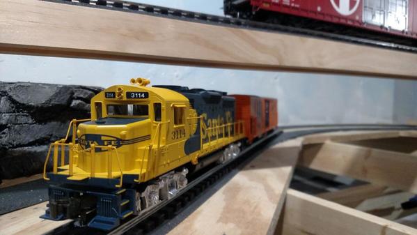
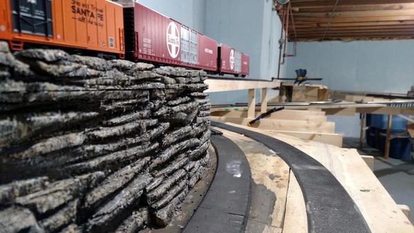
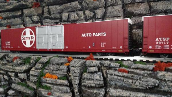
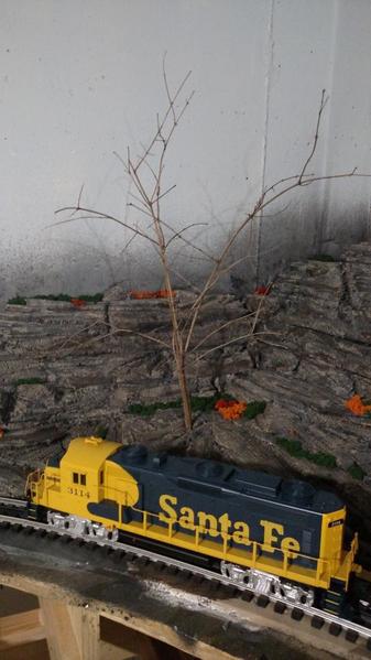
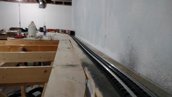
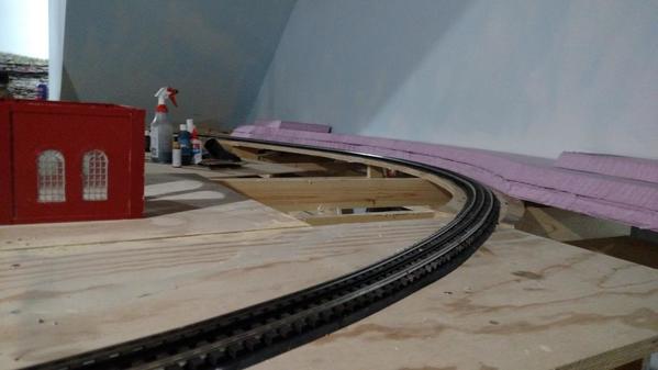
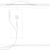
Here's my layout: The Topeka, Kansas City, and St. Louis.

Layout  features the Atchison, Topeka & Santa Fe Railroad around 1969-1971 - allowing for modeling of Super-C Service, Passenger Service, Mechanical Reefers, and Auto Parts service.   Also will feature rolling stock from roads I commonly saw on the ATSF when growing up in Topeka including the Frisco, Rock Island, Rio Grande, and M-K-T - but it is primarily Santa Fe.

Unfortunately, I started the layout not knowing enough about all the designations.  I've used Gargraves 3-Rail track to start - not knowing I could buy Gargraves 2-rail high.  Any future track or switch purchases will be 2-rail high and over a few years I'll either replace the 3-rail or remove the middle rail.  I suspect replacing would be simpler.  Plans  call for 100% Dead Rail operation utilizing BPRC and Bluetooth Control.  

Thanks for reading, thanks for all the help, and I hope you enjoy the process!

Last edited by Jacobpaul81
Original Post

Replies sorted oldest to newest

Yet another reminder why Killz was invented, I see.    Looks interesting.  How wide are the door and tall window, and how far is the window from the wall?  Are you able/willing to put table space in front of said window? I assume the door needs to be unobstructed.  How much space can you use behind the furnace/water heater between the stairs & 18' wall?


My first though was an around the wall layout w/a turn-around in the corner w/the window, running around in front of the stairs and the second turn-around behind the furnace next to (but not obstructing) the opening to the storage area. I was thinking I'd leave the storage area open as well as the space along the "door" wall & around to the stairs.  The alcove would allow you to taper the bench work to allow more room at the base of the stairs. Any idea what your turn radii will be?  Are you thinking traditional O gauge, or more of O scale?

 Your possibilities are endless in this space! Plan, plan, plan and then plan some more. This will be a significant investment with lots of enjoyment if you spend much time planning! My layout space is about the same square footage, but a different shape. Consider a walk-in style that provides easy access  to many parts of the layout!

023

020

021

013

003

Attachments

Images (5)
  • 023
  • 020
  • 021
  • 013
  • 003
Originally Posted by Fridge56Vet:

Yet another reminder why Killz was invented, I see.    Looks interesting.  How wide are the door and tall window, and how far is the window from the wall?  Are you able/willing to put table space in front of said window? I assume the door needs to be unobstructed.  How much space can you use behind the furnace/water heater between the stairs & 18' wall?


My first though was an around the wall layout w/a turn-around in the corner w/the window, running around in front of the stairs and the second turn-around behind the furnace next to (but not obstructing) the opening to the storage area. I was thinking I'd leave the storage area open as well as the space along the "door" wall & around to the stairs.  The alcove would allow you to taper the bench work to allow more room at the base of the stairs. Any idea what your turn radii will be?  Are you thinking traditional O gauge, or more of O scale?


Window is 2 ft from corner - Windows and door basically extend from floor to ceiling  and span roughly 10 feet.  My initial thought had been to run an around the wall dogbone setup along the length of the  16 1/2' and 25' area with turn outs by the stairs and the windows.  But at that time I was thinking smaller diameter curves so the windows would still be somewhat accessible.


My thinking now is much closer to your thoughts.  As most of the Rolling Stock and locomotives I'm looking at are scale size - I'm thinking differently.  I'm looking at gargraves wood ties, tinplate rails for the track - at O-80 and O-89 for curves- but thinking I could possibly go up to O-89, O-96.  Not looking for 100% scale level realism, but closer to it than to traditional.


I was thinking I could use the 18' wall, the 37' wall and alcove, and the first 10 1/2 -15' of the far wall & alcove.  Leave the storage room open along with the area in front of the windows, door, and around the mechanical.  This would be a good start - and down the line leave me plenty of space I could expand into if that became an option - or it'd leave plenty of room for a man cave space.   


This of course would put the water shut off into play. It's 3 feet from the alcove and protrudes 13" into the room.   


The pillar beneath the stairs is right at 9'6" from the 18' wall and sits 6' exact from the back of the furnace and water heater.  It's 13' 6" back from the 37' wall and 2' in from the stairs. So my initial drawing is a touch off on that one pillar.  As far as a pass through under the stairs, it's about 11' from the 37' wall where I'd feel comfortable walking under it - I'm 5'10".


Originally Posted by CLIFFORD:

 Your possibilities are endless in this space! Plan, plan, plan and then plan some more. This will be a significant investment with lots of enjoyment if you spend much time planning! My layout space is about the same square footage, but a different shape. Consider a walk-in style that provides easy access  to many parts of the layout!

You have a fantastic layout. I love the details.   I'm thinking around the room for much of the layout - however, where the 37' and 10 1/2 -15' foot walls meet, I've been thinking I might just need to take some sort of walk-in / duck-under approach if I'm going to do elevation differences around the walls. 

If I could twist your arm a little....This is "the" one thing I planned properly and I am glad of it.Design a layout that you can walk around the whole perimeter.I know,"that takes up more space"the benefit is while running trains it gives you different perspectives of your layout standing in different areas.It keeps things interesting longer.Guys that come over are constantly making that point about my layout.Good luck.Nick

I'm starting to get some ideas together for how to tackle this layout... I'll get some sketches together and share tomorrow for some opinions.  


Right now my plans revolve around an exterior dogbone mainline. One end under the stairs and the other in the 37' x 10' corner.   Inside that mainline is a parallel running figure 8 mainline - which crosses over at the water shut-off.  Each dogbone features an smaller radius interior reversing loop - allowing each mainline to reverse on one end of the layout.  I'm thinking walk-ins for each of the ends of the dogbone so you can have views observing the track around-the-room and from interior vantages.  Curve-wise I'm pushing towards 100" diameter - my drawings all call for O80/089/096.

I visited a local store today and got to check out the 89' and 86' Lionel auto carriers and boxcars and am seriously considering these as some primary freight for my layout.  They are right for the period I'm interested in and should work with the size of my layout.  My main concern is getting the mainline curve spacing correct.  


While I like the Atlas ties better, I'm leaning towards Gargraves and Ross combo for the track / switches. For those that use Gargraves / Ross - would I be better off using Flex or sectional to achieve the curves?  If sectional: Gargraves or Ross?

Originally Posted by Jacobpaul81:

While I like the Atlas ties better, I'm leaning towards Gargraves and Ross combo for the track / switches. For those that use Gargraves / Ross - would I be better off using Flex or sectional to achieve the curves?  If sectional: Gargraves or Ross?

The often published horror stories of Gargraves flex are much exaggerated in my opinion. I find it easy to work with....but I put down miles of flex in HO so maybe it's just me. I really like the look, ease and cost of GG Ross combo and I do have some GG switches too. 

Just get flex track. You'll save $. use it for the whole layout. Buy one piece of sectional curve for each radius to set up a jig. Watch the video on the GG site. Around the perimeter sounds good. You can always expand with a peninsula into the center.


there's a lot of great elements you can include. You can get maps and photos to help with your layout design. You have made it easier choosing a specific rr and a specific area to design your track plan. You'll just bend Kansas around for continuous running.

Here's a photo of Argentine diesel from the '60's.

Last edited by Moonman

As far as track goes I'd actually handle & look at samples of each to see what you like.  Your best bet cost-wise is clearly the GG flex, though the Atlas rail height & shape is more prototypical & is my preference.  You could also use the rail joiners/insulated rail joiners for power & blocking w/out any soldering or cutting.  You will pay for these conveniences, though, and Atlas is currently having production issues, so you have to factor that in, too.

Originally Posted by Moonman:

Just get flex track. You'll save $. use it for the whole layout. Buy one piece of sectional curve for each radius to set up a jig. Watch the video on the GG site. Around the perimeter sounds good. You can always expand with a peninsula into the center.


there's a lot of great elements you can include. You can get maps and photos to help with your layout design. You have made it easier choosing a specific rr and a specific area to design your track plan. You'll just bend Kansas around for continuous running.

Here's a photo of Argentine diesel from the '60's.

Thanks for the info!  So is it better then to preform - or form in place?  I've read some guys who say they prefer to work on the layout itself rather than with a jig. 

Thanks for sharing the photo.  Lot of good memories of that place.  


I'm a history librarian / archivist - my first gig was researching metadata and digitizing the Walter M. Andersen photo collection at Emporia State University.  I've noticed Santa Fe Online Resources has displayed the work: http://atsfrr.net/resources/Sa...0Service/Rhse-TT.htm  


Here's a copy of my first attempt at a track plan -  outer curves are drawn at O96 but could easily be over 100 - I'm a little concerned about getting too s-curvy - which is why I'm staying under 100 - even though I have room to go over.  Inner mainline is drawn at approximately O89 with the two reversing loops drawn at a graduated mix of O-89 and O-80.  


Was thinking about maybe doing an industrial area inside the loops by the stairs - maybe a brewery and train shop with the appropriate sidings. Other end would be your atypical Kansas town on a hill with trains in the river bottoms running around it.  


Elevation -  rear track is elevated and grades out at each end as it comes to the front. When at front, it's at low spot.   The inner track elevates from under the stairs - crosses over itself (figure 8) and remains elevated as it crosses in front of the water shut-off and over the duck-under - dropping in the reverse direction of the outer line.  I like that the figure 8 - and reverse elevations offer a nice contrast.  


Reverse Loops - The outside track tucks underneath the inner loop under the hill (see inset sketch),  wrapping around un-seen - emerging at the back corner of the walk-in.  The inner-loops reverse is a bit of a question-mark for me.  I didn't want three bridges at the stairs end duck-under, so I was thinking of putting a switch at the point the figure 8 drops - continuing the elevated track out - over it's lower self, then dropping it down to meet.  My concern is that might limit industry -  I'm thinking of adding a yard here inside this loop with a Topeka-esque shop and a Brewery. 

Attachments

Files (1)

Hi Jacobpaul81,

Here's an attempt at the outer mainline on the benchwork that you designed. It's done in SCARM, which is freeware. Gargraves and Ross were used. Flex for the straights and some curves that needed different arcs and sectionals were to used to easily identify the curves. Those will be flex in the final.


there's spacing issues to decide. I left 12" on the West wall for flats and scenery along the wall and 6" along the NW wall. It's 2"-3" to the edge of the table. Losing the wall spacing would open up the center if you needed it for track.


various size curves were used. The return loops are 106 and the smallest inside in the NE around the water main is 080. I had to use some custom arcs to fit the table in the East coming to the center to follow that angle. So, playing with that angle of the table can make the track work a little easier with 30°, 15°, and 7.5° increments. I had to use a 9° in two places.


I hope this helps you with your design decisions.


Photos and SCARM file attached.

Attachments

Images (4)
  • JacobPaul81 outer main concept
  • JacobPaul81 outer main concept 1
  • JacobPaul81 outer main concept 3D-1
  • JacobPaul81 outer main concept 3D-2
Files (1)
Last edited by Moonman
Originally Posted by Moonman:

Hi Jacobpaul81,

Here's an attempt at the outer mainline on the benchwork that you designed. It's done in SCARM, which is freeware. Gargraves and Ross were used. Flex for the straights and some curves that needed different arcs and sectionals were to used to easily identify the curves. Those will be flex in the final.


there's spacing issues to decide. I left 12" on the West wall for flats and scenery along the wall and 6" along the NW wall. It's 2"-3" to the edge of the table. Losing the wall spacing would open up the center if you needed it for track.


various size curves were used. The return loops are 106 and the smallest inside in the NE around the water main is 080. I had to use some custom arcs to fit the table in the East coming to the center to follow that angle. So, playing with that angle of the table can make the track work a little easier with 30°, 15°, and 7.5° increments. I had to use a 9° in two places.


I hope this helps you with your design decisions.


Photos and SCARM file attached.

Thanks Moonman!  That really helps - actually has really given me a better idea of what I can do with the space. Thank you for taking the time to put that into a SCARM file. I don't have a pc that I can download SCARM onto - we're pretty much mobile here at our house.   

The SCARM file really illustrated my concern that it was too snake-like on the one side. It also illustrated that I was under-utilizing that side of my space. While originally I wanted to be able to walk all the way around the outside of that end of the layout - I think a wrap-around internal view would better utilize the space - and make way for internal yards - once I get an idea of the mainline space.  I've done a mock up here that I feel like does just that.  

The mock - I've dashed in some edge of benchwork lines in certain places to figure out spacing some.  This moves the return duck-under bridge from the middle of the west space to right along the stairs - probably a double line lift bridge of some sort rather than  two duck unders.  The west reverse loop in this mock moves to where the previous duck-under return loop was located.  I've only left about 3 feet at the back for storage room access - should be plenty.  Couldn't get PDF to load - so converted to a jpg.


Originally Posted by Seacoast:

Nice Jacob and Moonman. How about sidings? Or a freight yard or better yet an engine service facilitiy, I like turn tables even though it might not fit into you theme or era. Best of luck.


Hi Seacoast - Thanks! Yea, trying to work out the mains first - once I get that worked out - I can plan for a yard or two.  This new mock-up I think better allows for that.  While a turntable doesn't fit the era, I would like a shop / engine service facility like the one in Argentine that Moonman posted before -  I may need to build everything else first and add this in over time - but I think the new design would allow for that to be within the current footprint.  

Track Plan 2

Attachments

Images (1)
  • Track Plan 2
Last edited by Jacobpaul81
Originally Posted by Moonman:

That layout has a nice flow.  I didn't do cut-ins. The purpose was exactly what you did. I also didn't round out the benchwork.


I assume the track is on the rear of the furnace and it's serviced from the front.(side opposite the track).


I'll mod the first file.

Moonman - 


Thanks! I really like the flow as well.  I see opportunities here for an internal yard in the lower loop with an engine facility - down the line, it would also be easy to add on a yard down the North wall of the storage room. 


Technical stuff: 


Yes, furnace and water heater are both serviced from the East side of drawing.  I'm thinking I will install a stud wall behind them to provide a backing between them and the layout - so layout would need to be completely accessed from inside in the furnace space under the stairs.  

 Looking at the drawing again, the stairs are under-sized to the east - they extend towards the furnace another foot or so - I drew them at 3 1/2 ft wide and I think it's closer to 4 1/2 - 5'.  I measured furnace last night and it was exactly 17' to the back from the 18' west wall. I looked at the stairs and if I were to run a stud wall along them, it would line up perfectly to slip behind the back side of the furnace.   

Getting around the steps doesn't work as you drew it without using areal small radius opposite the stairs. I bowed out on the approach then crossed an turned with 080,089.


That will be the tricky area, around the stairs. I have them at 180" from the west wall. Width to the east. 4.5' (54") from the North wall.

Attachments

Images (4)
  • Jacobpaul81 2D version2  trackplan
  • Jacobpaul81 3D version2 from above
  • Jacobpaul81 3D version2 from east
  • Jacobpaul81 3D version2 from west
Last edited by Moonman

Thanks for your help Moonman - somewhere I goofed in explaining the measurements -  it looks like I gave you reverse directions.  


The stairs are exactly 11'  (132") from the west wall and are 21' (252") from the East - so they overhang 6" past the west edge of the North alcove.  They sit 4' 9" back from the north wall - 6' 9" from the back wall in the North alcove.  That re-positioning should push the track back so that it can turn in the alcove with a bigger radius turn.  

Stairs are open underneath - so track can be curved under them - which was my plan.  I'll check the rise and run of the stairs again tonight but I believe it's not code (7"-11").  I'm 5"10" and at 11 feet from the North wall (13 feet from the rear of the alcove) my head easily clears by several inches.  That's roughly 10 x 10.5 rise - I knew those stairs felt steep!   At that rise, a train at a 36" counter height ( I assume most layouts are at counter height?)  - to achieve a respectable 10" of clearance- the center line would be set at 117" (9', 9") back from the wall - 141" from the rear of the alcove.  That'd cut the stair obstacle to get around to about 41-42"

Check my math - but that should work to aid in rounding the stairs.

Last edited by Jacobpaul81

Well, the snow stopped a little while ago, so it's machine time for this load. I'll mess with it later if I don't take a big nap.


I'm just counting blocks and guessing. Thanks for the stair location details. I was using 106 coming out of the South. It won't have to curve much. I had it parallel to the stairs, but it looked like you wanted a bump next to the stairs. If you want a narrow shelf, that shouldn't be a problem.


Have you decided on which track you'll use? I discovered much to my chagrin that the center to center spacing on the larger curves are 3.5" versus 4.5" so the track plan has different spacing.  Do have a preference for the spacing? I suppose on the large curves, you can get tighter than 4.5" as there is not much hang, except for the big  boy.

Last edited by Moonman

So, if your table height is 30", the rise to 37.5 or 38.5 to the bridge and overpass at the alcove, the incline under the stairs should stay under 36.


Going around the stairs you would raise the table height 42" and 50.5" at the bridge and overpass. The large radius doesn't make it look silly.


What table height do you want to have? I vote for 42" and get some step stools for the littles.

Last edited by Moonman
Originally Posted by Moonman:

Well, the snow stopped a little while ago, so it's machine time for this load. I'll mess with it later if I don't take a big nap.


I'm just counting blocks and guessing. Thanks for the stair location details. I was using 106 coming out of the South. It won't have to curve much. I had it parallel to the stairs, but it looked like you wanted a bump next to the stairs. If you want a narrow shelf, that shouldn't be a problem.


Have you decided on which track you'll use? I discovered much to my chagrin that the center to center spacing on the larger curves are 3.5" versus 4.5" so the track plan has different spacing.  Do have a preference for the spacing? I suppose on the large curves, you can get tighter than 4.5" as there is not much hang, except for the big  boy.

Wow - you've been busy!  My plan is to go Gargraves Flex with Ross Turnouts.  I'm concentrating on BIG cars - the Lionel 86' & 89' units and likely either the 18" MTH or 21" K-line streamliners - depending on availability.  I'd prefer the K-lines - in particular the High Levels - they would be more period accurate for 68-71.  At that size, I'm guess 4.5 would be more ideal.  To start I want to focus on building two big trains - I can add some misc. 50' boxcars or piggybacks later on.


Originally Posted by Moonman:

Here's the corrected step location. The steps are ok for when they were built. A 7" rise worked out. Not really that steep.

I measured when I got home - 8" rise, 9" step.   I re-measured everything to inches.  I'll scan it and get the inch measurements up tomorrow morning.  I'm off by inches in a few places.


Originally Posted by Moonman:

So, if your table height is 30", the rise to 37.5 or 38.5 to the bridge and overpass at the alcove, the incline under the stairs should stay under 36.


Going around the stairs you would raise the table height 42" and 50.5" at the bridge and overpass. The large radius doesn't make it look silly.


What table height do you want to have? I vote for 42" and get some step stools for the littles.


I'm thinking 35" lower level and 42" upper level.  That feels about right.   


My vision of elevation is a bit different than the representation here in SCARM - obviously something that was difficult to convey in a pencil drawing -  I'm actually thinking the reverse elevation-wise -  My thought was that the level coming around the stairs would be at 35" and that the around the wall (east side) would be at 42".  So inside the alcove, the stair track would tuck underneath and re-emerge, not go over the top and back across.

Where the east loop begins - my thought was that the inner loop would cross over itself - the lower level from the stairs would follow the outer level upper along the North wall.

To make things more interesting: the lower level outer loop (inside curve in the alcove) would feature a switch somewhere here to initiate a third track for a return loop which would follow along the Upper outer and lower inner along North Wall at 35" height. While moving along the North wall - the outer loop would begin it's descent - while the inner loop would begin it's climb to 42".  

Once through the switch, the Outer lower loop - exiting the alcove, would somehow cross under the inner upper loop and the two would cross two separate bridges. Once across, the outer loop at 36" would include a switch to tuck under the upper inner loop to create the connecting end of the reverse loop. 

If the east wall were at 42", that would create an upper level that I could surely put a cool yard in below with an entrance from the south inner loop that could span  that 18' wall at 36" creating a nice two level effect.

My two cents is make sure you leave room to remove any appliances when you build it check their size and how much space needed to move them, they have shorter life spans than layouts. I remember reading on a double decker layout years ago, not sure it would work with O gauge, but is a great space multiplier. use a lower level for a major yard, and require helper engines to get back out, a machine shop area. Something that looks good even with a short ceiling, low sky, under a solid straight away that is easy to reach and see above comes to mind.


Most important have fun and share the good times and good luck.

OK,

Took the latest info into account. main track height 35". Elevation to 43". Allow for roadbed and track height of 1" to bottom of elevated track support = 7" for Hi-Cubes and Auto-Racks.


Elevated from East access bridge to alcove along North wall and to midway on West wall.


Access aisle in West is 24"-28". Maybe you want a hatch or two instead. Lost a lot of real estate.


Corrected rise in steps and added back. Track comes out 5th step from top. Will the clearance be ok?


The mains are 0106 outer and 096 inner with 5" center to center rail spacing. Should be good.


The rest of the plan will come later if you like the mains. Issue with the turnback would be that a switch will be needed where elevation is declining at the East from the North alcove. That's the reason I elevated the run past the stairs and alcove loop back, too avoid that issue.


The turnback switch in the South would be before the stairs and stay on the table and curve up to mid-point in the East for the other switch. Crossing the open area would be a physical blockage and a construction issue on top of running into the elevation.


You need to keep in mind how large this is and that the loops are sweeping. They're not even close to something like and lot of 048\054 that you've seen or may have in mind.


I need the exact location of the water meter obstruction indexed from the alcove edge to confirm track clearance.


What do you think? Are we getting there? photo and multiple view pdf attached

Attachments

Images (1)
  • Jacobpaul81 3D version 4 track plan
Files (1)
Wow -  yea - I think we're really getting there.  The stair clears easily -  I measured a 10" clearance (cars would have 3" of space) 73" back from front of stair. - thats at the 6 step going up.  I gotta get actual measurements scanned - it'll happen this afternoon.  

Water sticks out 12"  and is exactly 36" from alcove.  I was attempting to draw it with an additional 12" of clearance.  It sits at 40" from floor.


I am curious what your and others advice might be as to the curves - I am concerned that while 106 may look better with the big cars, that its too large and I should max out in the 90-96 range - sacrifice some of the more scale look to gain back some modeling space.  Thoughts?

The curves are not costing you any space. There is 8" on the west and the NE wall, the alcove, the corners if you don't round the table, 17' x 9" in the SE.


You have your choice of what extra track and radius if you want something inside the mains.


When the plan is done, you'll need about 80  + pieces of flex track to build it, plus switches and specials.


Just the two mains need are 80pieces to build as shown. The sectionals are only there to identify the curve. I get an exact count when they are converted to flex. 245' feet of track.


The water clears by 3.5" and 5" higher where the e is in slope on the track plan. Sounds like a mountain.


Do you want to cross the opening or create an r-loop in the SE to East?


You could a point-to-point with a r-loop in the center and run that line next to main in the N. The inside main could switch on and off of it. That could be the branch line to service freight or passenger and connect to a yard or something like that.


I'll wait while you ponder. Thought the pdf would work on mobile.


Last edited by Moonman


copier@slcl.org_20150306_182439 [1) (1)


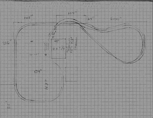
Here's the actual measurements in inches so we can be more exact.  Stairs are actually 131" from west wall, not 132"  - and they hang out 17" past the alcove -  which is 6" larger than I thought. Stairs sit back 56.5" from North wall, 80.5" from rear of alcove. 


Pillar is 113" from the North Wall, 116" from the West, and 163 from the south.  Same positioning for pillar on the east side - which I forgot to draw here.


There's 276" from North to South wall - I need to leave  36" off the south end - no appliances to move out of storage - just plastic tubs and Christmas decorations.  It's 174" from the west wall to where I plan to wall in behind the furnace. 43" of those inches extend past the stairs.  The North east wall is 200" - and the West wall is 126" to the alcove -  there's plenty of room here if we need to bump out a bit more south.

Attachments

Images (1)
  • copier@slcl.org_20150306_182439 (1) (1)
Originally Posted by Seacoast:

Interesting thread. 0106 curves are great but eat up a lot of real estate. What will you be running that requires these huge curves?

How does a large radius curve eat up real estate? It's only 3 1/4" wide. With flex track you can have any radius curve that you want. I want to understand this comment.


Do you enjoy straights more? There's plenty of 10' straights on this layout.

Last edited by Moonman
Originally Posted by Moonman:
Originally Posted by Seacoast:

Interesting thread. 0106 curves are great but eat up a lot of real estate. What will you be running that requires these huge curves?

How does a large radius curve eat up real estate? It's only 3 1/4" wide. With flex track you can have any radius curve that you want. I want to understand this comment.


Do you enjoy straights more? There's plenty of 10' straights on this layout.

Carl, no offense meant. 096 and 106" diameter is what 8-9' wide curves unless your running the track plan around the walls, big curves take up a lot of real estate or area in any given space right? If one has the room for big curves go for it, why not life is short, and scale 3 rail engines look better on bigger curves.

I have a track plan dilemma myself with rr track. In the near future I would honored if you would give your opinion on few plans I have.


By my calculation, there is 174" east west size constraint - and from south to the point center rail must cross by to get under the stair is 173".  So if theres a 4 "  edge around the southern edge of the exterior track, thats still 169".  Not sure where the 83" is coming from.


Originally Posted by Moonman:

That makes the SouthWest table about 83" , leaving a tight 072 maximum radius in that area.


"Measure twice and cut once" 


Now, what? Smaller curves on that end? There goes that track plan.


Now, you have good measurements to work from

Originally Posted by Seacoast:
Originally Posted by Moonman:
Originally Posted by Seacoast:

Interesting thread. 0106 curves are great but eat up a lot of real estate. What will you be running that requires these huge curves?

How does a large radius curve eat up real estate? It's only 3 1/4" wide. With flex track you can have any radius curve that you want. I want to understand this comment.


Do you enjoy straights more? There's plenty of 10' straights on this layout.

Carl, no offense meant. 096 and 106" diameter is what 8-9' wide curves unless your running the track plan around the walls, big curves take up a lot of real estate or area in any given space right? If one has the room for big curves go for it, why not life is short, and scale 3 rail engines look better on bigger curves.

I have a track plan dilemma myself with rr track. In the near future I would honored if you would give your opinion on few plans I have.


No problem, I am just trying to understand. Needing a large width is obviously needed. I interpret 'taking up real estate" as having a high track to scenery ratio type layout. The size of the curve doesn't have anything do with that.


I have RRT. I could look at your file. Email in profile.

Last edited by Moonman

Well clearly even my revised measurements are off.  My wife's ADD has clearly been transfered to me this week - I'm normally pretty accurate with this stuff - that said, there's a reason I'm not a Architect. =)  I believe in my original calculations I left 2'  off. The south wall depth increases from 300" to 324" opposite the furnace - it was left off previous plan drawings - which with the 12" you've left =  36".  
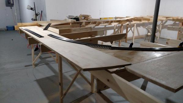

The computer and paper weren't quite working visually for me - so I spent my evening with a sharpie, string, straight edge, and measuring tape laying out on the floor a track plan utilizing O100 on the outside loop and I drew it at O90 on the inside loop (with O100 gradual transitions) - this is drawn moving from a 4" center to center on straights to a 7" center to center on the curves and it looks great to me.


So, there is space there.


Are you sure you want to scribe you own arcs when you lay the track?  That's a lot to bite off on you first layout.  Those two radius tracks would make a natural 5" c-t-c and wouldn't require easement tracks.


The 0106 & 096 have a 5" c-t-c.


Some masking tape on the floor for the table helps, too.


Last edited by Moonman

Please use Moonman's idea! Mark out your layout on the floor with masking tape, It will give you a real feeling for how things will look and work with the space allotted! Keep your isles at least 24" wide, you will never regret having at least that much width. I have an isle much like yours, it is 18" wide by 11' deep, and it is difficult to maneuver. I have a 36" waist, and I am unable to turn around in that space comfortably! Regards, Clifford

Originally Posted by CLIFFORD:

Please use Moonman's idea! Mark out your layout on the floor with masking tape, It will give you a real feeling for how things will look and work with the space allotted! Keep your isles at least 24" wide, you will never regret having at least that much width. I have an isle much like yours, it is 18" wide by 11' deep, and it is difficult to maneuver. I have a 36" waist, and I am unable to turn around in that space comfortably! Regards, Clifford

Definitely plan to - and yea, I can't visualize an aisle under 24" wide - that just wouldn't work.  24" required.


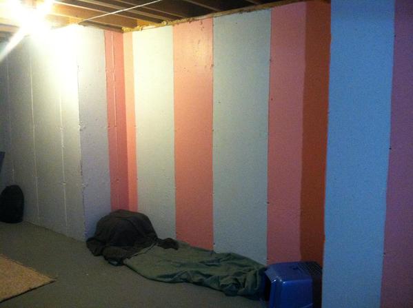
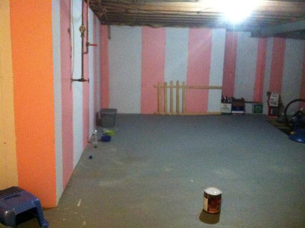
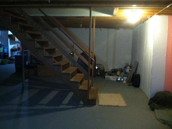
Spent my day painting - the pink is finally gone after 5 coats of Kilz. It wouldn't die.


I've got everything drawn out on the floor except the internal yards for the Engine house and Brewery.   Both will be in the western loops - I'm planning the brewery to be on the south east side of that loop inside the curve out towards the furnace.   Planning the Engine House to rest towards the Northwest corner at 36" - sitting below and in front of the climbing mainline - The yard can run the length of the 18' wall.

I'm planning to do all the work right on the benchwork rather than pre-curving - I feel like this will work much better for me personally.  


Spent some time at the big box stores yesterday -  Planning to use an L-girder benchwork construction - 1 x 4 and 1 x 2  for the L girder, the wall side mounted right on the concrete - the interior l-girder + the benchwork that doesn't have a wall on 2x3 posts (which were cheaper than 1x4s)  then use the  1 x 4 s for cross supports as well.


 Not sure what the best underlayment is - something strong and light I assume - I plan to cut to the track and use a combination of thin plywood and foam for the majority of the layout - what's best?  OSB, MDF, a certain type of plywood?  How thick?   They don't carry homosote - but they do carry quietbrace - so I'm thinking I'll use that as a noise reducer. 

Last edited by Jacobpaul81

OSB and MDF don't hold screws well. You need to pre-drill a pilot hole for every screw for a good bite. A flooring grade plywood would work. Everyone likes 3/4". It's so thin now the nominal is a little over 5/8".


Don't use the quietbrace. It's meant for exterior use and has a black goop on it. Did you check that out? Not much for sound attenuation.


Originally Posted by Moonman:

OSB and MDF don't hold screws well. You need to pre-drill a pilot hole for every screw for a good bite. A flooring grade plywood would work. Everyone likes 3/4". It's so thin now the nominal is a little over 5/8".


Don't use the quietbrace. It's meant for exterior use and has a black goop on it. Did you check that out? Not much for sound attenuation.


3/4" Flooring Grad Ply -- Check. Got it. 

With the quiet brace I'd read guys have been painting it before cutting it. I figured I could do that... but it is a lot of extra work...


Another option I'm considering is just gluing cork directly onto the plywood -  at nearly $50 for 75 feet, it's not exactly low cost - but significantly less work and looks good.  The question there then is, do I still need additional noise reduction?  If I shoot caulk in-between all of the joints, will that help reduce vibration noise?


This is always an interesting topic. Before I forget, congrats on your track plan. You sound like a man that wants to build a railroad and has a plan.


When I observe a published layout builder like Norm Charbonneau, just put cork on roadbed on top of ply and others, too, I have to think it's works. Elliot(Big_Boy_4014) with his massive layout and experience, takes the time to cut the homosote into roadbed. Some will still go for the overkill and use both.


The sound attenuation of cork is up there with many modern materials. I think you'll be fine with just the cork. Since you are mobile, the app store has a free decibel meter called DB10 for iOS. Compare with sheets of homosote pricing at $29+_ a sheet. I think it about the same. Yeah, it's another cost. By the way, Home Depot calls it by the marketing name, Soundboard 440. It's usually in the section with the foam insulation. Many times, the staff doesn't know they have it. 


Another trick I just saw a guy use, was to put strips of a quality carpet padding on the tops of the joists before screwing down the deck. Isolate the deck from the framing. I liked it and believe it will help.


Care to share a photo of the floor marked out? Who would have thought pink would be that hard to cover. I use the oil based Killz for those jobs. You still need to put a primer for the new wall paint or get a paint primer combo. The colors won't turn out correctly over Killz.


Last edited by Moonman

Thanks Moonman - I appreciate all the help - has really helped in getting me going.  


I was leaning towards cork right on the plywood - the fact Norm does it makes me all the more confident - his layout work is among the most impressive I've seen - certainly pulling some inspiration from there.  I'm planning on painting my ceilings black like he has and adding track lighting in a similar vein.  His low-relief buildings are incredible - I'd like to try to use some of that as inspiration on my west wall - perhaps a West Bottomsesque look to it - 


I'm trying to figure out now how I want to deal with the backdrop.  Looks like most folks use Masonite - not sure if I should, or just paint a basic sky blue and light clouds on the concrete. 


Originally Posted by Moonman:

Check this photo for correct basement wall dimensions. The see the blue numbers for the benchwork dimensions. I had 1' where you need 3'. That 2' squeezes the 108 table width behind the stairs down to ~83"


See note at bottom. Is this dimensionally correct for the space perimeter?

Jacobpaul81 Basement outline

Nice layout plan Moonman, I"m also building a big layout in my basement. Right now I'm stuck with a small test track on my basement floor. I doing a youtube series on the layouts construction and train stuff. My channel name is Dans Trains https://www.youtube.com/channe...4ivkEenZvSWXHOZpQWdg here are some videos of my test track and basement.  

Check it out! Also if you guys have good layout building advice when it comes to benchwork I'm all ears!

hey Dan's Trains,

It is JacobPaul81's plan. I just put it to a computer app. See his pencil drawings above.

I watched your USA SD60 video. Nice engine.

I like L-Girder with the personal variations that I have seen. It's a sturdy compact system that's very flexible to fit you design. I favor around the walls for most designs. If you have a huge room, a large full walk around is nice.


Lots of framing and decking variations. Search the forum and the web for model railroad benchwork.

Last edited by Moonman

Jacobpaul81,

I had an idea for the alcove at the bottom of the steps...make it a mountain with tunnels. A front with portals and a top. You could leave a flat spot for a vignette on the mountain. You could make a cool gorge under the bridge(s) by cutting out part of the table. maybe a waterfall down from the mountain. It would be a nice site going down the steps to the train room.

added the wall behind the furnace at 174" from the West and 43" to the South.


I adjusted the table , but kept the old track plan.


Attachments

Images (2)
  • Jacobpaul81 v 4 tunnel in alcove SSE view
  • Jacobpaul81 v 4 tunnel in alcove SW view
Originally Posted by Jacobpaul81:

Thanks Moonman - I appreciate all the help - has really helped in getting me going.  


I was leaning towards cork right on the plywood - the fact Norm does it makes me all the more confident - his layout work is among the most impressive I've seen - certainly pulling some inspiration from there.  I'm planning on painting my ceilings black like he has and adding track lighting in a similar vein.  His low-relief buildings are incredible - I'd like to try to use some of that as inspiration on my west wall - perhaps a West Bottomsesque look to it - 


I'm trying to figure out now how I want to deal with the backdrop.  Looks like most folks use Masonite - not sure if I should, or just paint a basic sky blue and light clouds on the concrete. 


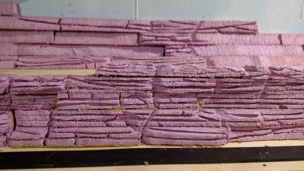
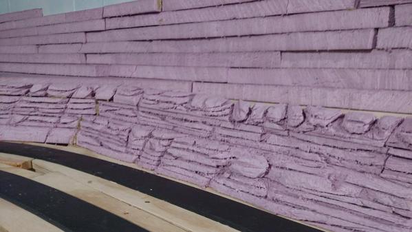
Very few clouds look ok to me. But a blue sky with building flats or foam board carved like rocks gives some 3D to the layout and a transition to the sky.


The Masonite lets you do whatever you like and remove without messing with the walls. The photo backdrops always look cool. Blend the sky colors to the backdrop sky.


That's what looks good to my eye.

Originally Posted by Moonman:
Originally Posted by Jacobpaul81:

Thanks Moonman - I appreciate all the help - has really helped in getting me going.  


I was leaning towards cork right on the plywood - the fact Norm does it makes me all the more confident - his layout work is among the most impressive I've seen - certainly pulling some inspiration from there.  I'm planning on painting my ceilings black like he has and adding track lighting in a similar vein.  His low-relief buildings are incredible - I'd like to try to use some of that as inspiration on my west wall - perhaps a West Bottomsesque look to it - 


I'm trying to figure out now how I want to deal with the backdrop.  Looks like most folks use Masonite - not sure if I should, or just paint a basic sky blue and light clouds on the concrete. 


Very few clouds look ok to me. But a blue sky with building flats or foam board carved like rocks gives some 3D to the layout and a transition to the sky.


The Masonite lets you do whatever you like and remove without messing with the walls. The photo backdrops always look cool. Blend the sky colors to the backdrop sky.


That's what looks good to my eye.

That's about what I was thinking as well - simple backdrop - more 3D dynamic modeling to the background than "Art". 

Originally Posted by CLIFFORD:

Please use Moonman's idea! Mark out your layout on the floor with masking tape, It will give you a real feeling for how things will look and work with the space allotted! Keep your isles at least 24" wide, you will never regret having at least that much width. I have an isle much like yours, it is 18" wide by 11' deep, and it is difficult to maneuver. I have a 36" waist, and I am unable to turn around in that space comfortably! Regards, Clifford

My original track plan was done by a pal who didn't have a good preception of the areas the track would need. He was drawing for On30 but thinking HO. In the end, one aisle was comically thin, maybe a thin teen could have fit if standing sideways and even then it'd been a tight fit.
I bought several sheets of poster board, laid it all down 1:1 scale and drew the actual curves to see what would really work out. I had to re-design the center section of the layout from that. I'd already cut and nailed lumber together by then but I didn't get any further and the changes weren't that bad as I only needed to change one section, all from looking at the paper 1:1 representation.

Frankly, I don't trust computer projections, I've heard too many horror stories about how when the track laying started, it simply didn't work like the computer said it would.

Originally Posted by p51:
Originally Posted by CLIFFORD:

Please use Moonman's idea! Mark out your layout on the floor with masking tape, It will give you a real feeling for how things will look and work with the space allotted! Keep your isles at least 24" wide, you will never regret having at least that much width. I have an isle much like yours, it is 18" wide by 11' deep, and it is difficult to maneuver. I have a 36" waist, and I am unable to turn around in that space comfortably! Regards, Clifford

My original track plan was done by a pal who didn't have a good preception of the areas the track would need. He was drawing for On30 but thinking HO. In the end, one aisle was comically thin, maybe a thin teen could have fit if standing sideways and even then it'd been a tight fit.
I bought several sheets of poster board, laid it all down 1:1 scale and drew the actual curves to see what would really work out. I had to re-design the center section of the layout from that. I'd already cut and nailed lumber together by then but I didn't get any further and the changes weren't that bad as I only needed to change one section, all from looking at the paper 1:1 representation.

Frankly, I don't trust computer projections, I've heard too many horror stories about how when the track laying started, it simply didn't work like the computer said it would.

Thanks for the input!   I've got everything drawn out now except my inner yards -  not sure how I'm going to approach that yet - wondering if I should build the exterior benchwork along the west wall using L-girder - then once I've got everything the way I want it, come in and build a standard table for the lower level yards. 

Hey P51,

My designs fit perfectly, which is why I need accurate measurements and an accurate table build. One guy shorted his table 7/8" of width on each leg because "close enough" was good for him. You can guess that the track didn't fit.


JacobPaul81 drew it on the floor to make sure of his fitment. Passenger train collector did his new Christmas layout on red rosin paper.


The planning and building are two different acts. A good plan always makes the build execution easier.


The ancients didn't need more than string to build level and plumb structures, but there had to be something of a plan to guide them.


The software is like any other tool, it depends who is using it.

Last edited by Moonman
Originally Posted by Jacobpaul81:
 

Thanks for the input!   I've got everything drawn out now except my inner yards -  not sure how I'm going to approach that yet - wondering if I should build the exterior benchwork along the west wall using L-girder - then once I've got everything the way I want it, come in and build a standard table for the lower level yards. 

Add another hanger(arm) to the pylon or just attach another set of girders to legs if you use that style. The L-girder should be able to span 6'-8' with no center support to block the view..

Following a train store visit, the wife is now very much hyped. She was like a kid in a candy store.  So I'm in full gear -

Painted walls with Killz primer - Drew out track plan with sharpie on floor and taped out benchwork edges - I'm going to expand the East side a bit towards the south wall so that there's more distance from track to layout edge. Calls for a 34" aisle - once I figure out exactly how I'm going to build the table, I'll tweak the aisle some to allow me to reach the east wall as that's the one place I don't have easy access to. 

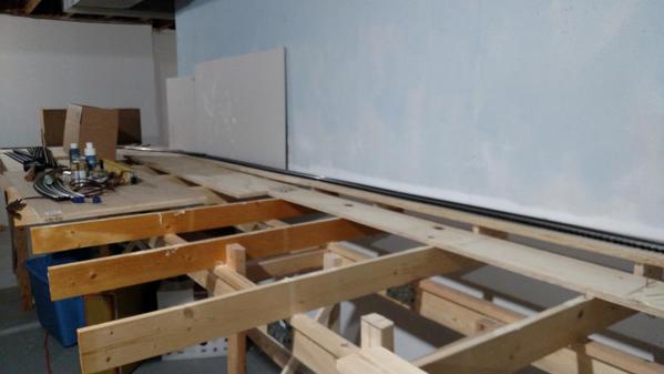
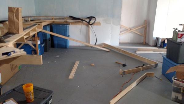
I've started constructing L-Girders for the concrete walls.  Also have furring cut for mounting the backdrop.  I'll start mounting this with tapcon screws this week. Hope to have the wall L-girder, backdrop up and painted, and would like to have the new walls around the stairs installed by weekend's end if at all possible.  Then I'll be redoing the floor with speckled garage paint before I delve into building the interior L girders and bench legs.   

Making a few tweaks to benchwork height -  we planned for 35" and 42" - I'm going to raise that up to 38" and 45" - around the stairs I'll lower the benchwork itself to 35" and put the track on risers - that way I can model a steep rivers-edge around the tight space

Here's some photos

photo [1)

photo [2)

photo [3)

photo [4)

Attachments

Images (4)
  • photo (1)
  • photo (2)
  • photo (3)
  • photo (4)

It's beginning to look like something! Your elevations  sound good. Keep your access isles wide enough to move freely! If you will have a "duck-under" or lift out section try to place this at the highest height! you will be crawling under that bridge often. Any derailments will occur on the opposite side of which you are standing(LOL). Keep up the good work!

Attachments

Images (1)
  • IMG_0198

Hammer drill, drill a pilot hole, then the tapcon with a hammer drill. They can be a pain.


Makin' it happen now. Good plan B on the backdrop.


Thanks for the update. hey, like others suggest that follow the builds, update your post title with "xx\xx\xx update". You have more fans than you think. Everyone learns from builds.

A little more intense. Drill a 1/2" hole in the concrete and use a lead set. These require a setting tool usually included in the product box. There are hollow wall set tools also.  Usually requires a 1/4" X 20 X length  machine screw.  As you drive the expanding lead against the tapered steel piece it tightens in the wall.


Greelee Hollow wall set tool.   The lead set threads to the one end of the tool. It is inserted in the wall and then hammered tight.  Tool is backed out, fastener is ready for a 1/4" X 20 bolt.  The tool also compensates, if your hole in a concrete wall is too deep. It hold the fastener at the wall surface.

Last edited by Mike CT

Jake,


Don’t dismiss QuietBrace too quickly. I used Homasote on my first five layouts (1966 > 1993), but was not able to find it for my sixth layout (first O-Gauge, in 2009) so I used QuietBrace instead. That layout was approximately 7-ft x 20-ft and I painted the QB grey.


For my present layout (about 1000 Sq-Ft), started 2011, I did not even bother to look for Homasote because I liked QB better. As far as I can tell, QB is just as good as sound insulator as Homasote, and everyone else who has used it (many here in this forum) likes it. This last time I started painting the QB as I had done previously, but after painting the first four sheets, I stopped. I realized that the surface will not be exposed, and any that would show under the ballast would be just fine left black.


The black stuff could stain your shirt and pants if you rub hard against it, and may make your hands dirty, but this is really a very small issue. Besides, it offers a bit of protection as it makes the surface just a bit harder. I cut the QB the same as I used to cut the Homasote – with a utility knife. I cut curves and angled cuts (to simulate roadbed) with a saber saw and a knife-edge blade. All of these cutting methods result in zero dust.


I just looked at the current prices, and Menard’s has 1/2"x4'x8' Homasote for $26.99, and Home Depot has 1/2"x4'x8' QuietBrace for $10.35.


Good luck with whichever method you choose!

Alex

Last edited by Ingeniero No1

Beautiful weather and commitments have slowed me down some -  I've installed studs around the stairs and hung Sheetrock I had on hand from other remodeling projects.  My next step is to build the wine rack under the stairs -  I'll use that for the support structure for the L girder and bracing under staircase.  I'm going to shift my south table towards the west wall and use triangle bracing as I've used along the stair wall to wrap up the wall behind the furnace. 


I'm rethinking this section of the layout for modeling purposes.  I'll know for sure once the wine rack is done, but I'm leaning towards fitting my brewery under the staircase using the wine rack as the construction base.  If I shorten the south straight a hair, then I can add a switch in front of the furnace and put in some industry sidings under the stairs.


Originally I was thinking of using the west wall for my engine yard, but if I move the brewery under the stairs, then It can utilize the South table top, making it more of a focal point - and pushing the industry completely to the south section.  That'd add some modeling room along the West wall and north wall for more country scenery.


In the area around the water main, I think I can reduce my distance from the wall -  I built the table under instead around the main - I'm gonna try and build a water proofed box to model cliff face on to cover the main and make it easy to remove and access.  On this side I'm looking to figure 8 the inner main -  rather than run two double mains parallel - I'll cross the lower inside line underneath the upper inside line -  this will reverse train directions creating a less linear and more multi- level experiance.  


This means the duck under bridges will be 7" height difference with the inner line being 7" higher.  I'm hoping to install two left switches - one before and one after the bridge on the outer main -  this will be used to create a reversing loop which will tuck under the outer main right after the bridge.  As the inner main drops 7" along the north wall - @ 2% should roughly be 30ft - the two should level out at the water main and parallel each other - I'm thinking about installing a Ross double crossover here.   That'd allow multi directional use of both mainlines creating a maximum mainline track length of roughly 275 total feet -while adding additional action to this end of layout - which is predominatly visaual in use.


Finally -  going to clear out my previously acquired toy train stock.  Already unloaded a few items.  I've got 4 89' Santa Fe autoracks and 2 of the 86' boxcars that should be here this week - 12' of train to pair with a future Diesel purchase. Trying to decide what other mixed freight I should pick up to pair with these - was thinking some scale tank train tankers, maybe some Evans plug doors, but open to ideas. Looking for scale period locos - F7s, Sd45s, FP45s, SD40-2s to run. Unfortunately, the locomotive builders haven't done much with the locos of this period - there's a few sd40 /45 options - but I've only found an MTH (and a to be released 3rd Rail) F7 scale paint correct model and the MTH and Williams FP45s are both inaccurate - with only MTH releasing it in freight scheme. 


Attachments

Images (3)
  • image-7
  • photo-2
  • image-6
Last edited by Jacobpaul81

The framing is coming along. Yep. life and family come first, then you head to the train room for some quiet time on simple things.


I had to go back to that Southwest table width issue. I was thinking that it had to loop back to the west and across the space all on that table.


Thinking through your scenery as you build the framing is  good process.


I like the idea of the reroute around/under the water main and the adjustment to the east end. That end was always an afterthought during the design. This sounds like a good refinement without major changes. I don't think it needs to waterproof. If something happens there, it will be major. Don't park any trains there.


I used a frame with screen and Right Stuff foam to make a cover to hide a wall problem. The foam is hard to carve, but it's a cool shell. I think that I could have used 1/2" or 1" foam insulation board to make a "box" to hide the obtrusion and still carve rock look into it. A few squares of adhesive backed Velcro can make it removable.


Thanks for the update and photos.

Last edited by Moonman
Originally Posted by Moonman:

I had to go back to that Southwest table width issue. I was thinking that it had to loop back to the west and across the space all on that table.


I used a frame with screen and Right Stuff foam to make a cover to hide a wall problem. The foam is hard to carve, but it's a cool shell. I think that I could have used 1/2" or 1" foam insulation board to make a "box" to hide the obtrusion and still carve rock look into it. A few squares of adhesive backed Velcro can make it removable.


Thanks for the update and photos.

 Thanks for the response Moonman.   I was thinking I might build a simple plywood box, spray the inside with Flexseal, and do something similar to what you describe with Foam to the outside.  Keep it simple enough to lift up, and maybe put a wedge in it to direct water away if something were to happen.  


The southwest is a 90 degree turn from the open area to along the backside of furnace. If a train's headed east, it makes a 90 degree North.  At 102 center diameter, this is 25.5 on center - requiring just under 3 feet .  

Behind the furnace, there's roughly 13 feet from the south edge of the planned table to the point at which the trains must clear the stairs.  The 3 feet leaves 10 feet of travel to work with.  

In order to clear the stairs, a train must make a 45 degree which at 12.75 on center should require a generous 2 feet with clearances.  So we're down to 8 feet.  It must also travel out 3 feet once it's made it's turn in order to clear the stairs. Leaving 5 feet.  


To wrap the stairs, it must also make another 45 degree. This turn could eat up 2 feet - but depending on how close it is to the stair will determine that figure.  If it's at minimum, it will only take about 6-8" as the other half of turn will be past clearance.   So we're down to about 3 to 3 1/2 feet of play. This means there's about 1-2 feet straight behind the furnace between the 90 and the 45. Logic dictates that the sooner the initial 45 turns,  the more it will clear the stairs.  So there is 1-2 feet there for a switch if one were to put one in. 


That said, a slight modification to the travel of the south most run can result in more options.  The shorter the south run gets, the less return travel the 45 to 45 requires (obviously there are diminishing returns).  Pushing the trains into the room 6" adds back 6"to the straight section behind the furnace.  So depending on the needs of a Ross switch - there should be room to do it off the straight.

Not much donre on the layout this weekend -  landscaping took priority...though I started the wine rack and mounted the l- girder under there stairs.  Think I will wrap up the bench work framing Wednesday.   


Received a big package on Thursday.  Pricey but will make up a major focus of my railroad.  


Considering modifying my plan some -  was going to make it all conventional -  but thinking I'd be better to set it up for command from the start -  skip the transformers and just run everything off power bricks and a legacy system -  cost seems much better and most the scale locos are already command equipped.  While MTH offers several locos I'm interested in ( Cigar Band Santa Fe F7 & FP45), neither is PS3 yet - Atlas is TMCC as is the Lionel F7 warbonnet I'm looking at for my passenger line - so legacy makes more sense.  As Im about ready to start wiring, I need to get a handle on how to set it all up -  


Does each main need a brick, or could I block layout in half at stairs and have a brick on each side - saving nearly half the wire?  


Do I need a dedicated brick for the reverse loop or can that be on one of the mainlines?


 Will yards need dedicated bricks?  


Other things I haven't thought to ask?

If you have sufficient receptacles around the walls and a main switch for the layout power, bricks in areas work and it will make wiring a little easier.


The other approach is one hot for each main end to end(a bus) and then just one common. The commons all use the same.


12awg is nice , but 14awg works. Can use house wire for the bus or what ever you find that is the least expensive.


The bus also makes it easier to pre-drill the holes in the joists and feed the bus wires before installing the deck.


Yard could have it's own power, or you can control it remotely with a couple of TMCC or Legacy devices. like the SC-2 or BPC-2.


Tell me where you'd like to locate the bricks and base. I'll sketch a proposal.


Check out Ingenerio 1(alex) and Laidoffsick. They have some large layouts for Legacy.

Originally Posted by Moonman:

If you have sufficient receptacles around the walls and a main switch for the layout power, bricks in areas work and it will make wiring a little easier.


The other approach is one hot for each main end to end(a bus) and then just one common. The commons all use the same.


12awg is nice , but 14awg works. Can use house wire for the bus or what ever you find that is the least expensive.


The bus also makes it easier to pre-drill the holes in the joists and feed the bus wires before installing the deck.


Yard could have it's own power, or you can control it remotely with a couple of TMCC or Legacy devices. like the SC-2 or BPC-2.


Tell me where you'd like to locate the bricks and base. I'll sketch a proposal.


Check out Ingenerio 1(alex) and Laidoffsick. They have some large layouts for Legacy.

At the moment, there are no recepticles -  so I'm free to wire at will -  right now there are two separate lighting breakers for the room -  my plan was to wire all the lights to an active switch and take back the second breaker for the layout -  so I could run lines across ceiling and drop just about anywhere -  Ideally I was thinking that the stairs would be the best place to wire in a switch and control area as well as power as it would be easy to cut the layout on half - but the lift bridge troubles me -  I could wire one block in at a stairs and run from the bridge to where it joins .  I coukd then run power from the switch over ceiling, drop it in the alcove and install two more bricks - one going west and the other going south west - having them meet at west wall.    Seems there most efficient use of wire.  Then if the yards needed their own, iitd be easy to install at the stairs.


I'll check out those layouts and see how they handle the large runs.

here's Alex' Hidden Pass Junction. he is using DCS. Wiring scheme is May 1, 2011 post with diagram.


So, depends if you envision running both systems at some point. Susan Deats (splrr)has no problems with a bus and DCS\Legacy.


A couple of modular clubs with large layouts that travel, need to use a bus by design, and have had some dcs issues which they resolved. National Capital Trackers and North Penn O Gaugers. 

Definitely going to go for just Legacy - Wiring is not my strong suit - so I want to keep things as simple as possible - if all I've gotta do is run power bricks to wire connected to track, that sounds ideal. 2 systems or 1 system and a transformer seems way more difficult.  

While MTH has some nice looking equipment, most of the motive power I'm interested in from them is conventional.  As Weaver and Atlas have produced way more period options - and often TMCC equipped - supporting them with the hope they'll fill some of the missing options in future catalogs seems the best route.  


Layout construction is in standby as the weather has cleared - lots of landscaping to do.  Decades of neglect has me outside digging footings for retaining walls and building flower beds.  I'll start wrapping up Benchwork if it starts raining again. 


 I told you guys I got a nice package in the mail the other day - Easter special from trainworld.  4 89' Autoracks and 2 86' boxcars.  They are BIG. Can't wait to get them on the layout with some EMD locomotives.


image [5)


Autoracks


Attachments

Images (2)
  • image (5)
  • Autoracks
Last edited by Jacobpaul81

Well -  ive changed my mind -  I'm sure that's super common -  going to go with DCS to start and will add tmcc later if required.   After further research there are far more ps2 options than TMCC options for my modeling period.


Put Ina cork order -  going to put in a track order for one case to start -  going to start with the outer loop and get that up and running, then delve into the inner loop.  This will require a right and left O96 Ross switch -  am I better off with manual or with one of the two switch matching options?


For DCS -  I've looked over the star wiring -  the power source to the tiu then from there to terminal blocks which star out to the track.  Correct?   If so, should one lionel 180w and two terminal blocks be enough for a 116' mainline and the 20'  reversing loop?

You will probably only need one terminal block.  It is recommended that each block be about 8 to 12 track sections regardless of length.  If track is soldered together than that counts as one track section.  The recommended block should be no longer than 100 feet regardless of the track sections.


Depending on number of sections I would probably have about 4 to 6 blocks for that length of track and you have enough to do 12 on a MTH Terminal block.  Remember to use 16 gauge wire and try to make each wire coming off the terminal block the same length.  Also add an 18V light bulb across the terminal block.....  this improves the DCS signal.  See the DCS forum and magic light bulb for further info.

Originally Posted by metjetnrailfan:

You will probably only need one terminal block.  It is recommended that each block be about 8 to 12 track sections regardless of length.  If track is soldered together than that counts as one track section.  The recommended block should be no longer than 100 feet regardless of the track sections.


Depending on number of sections I would probably have about 4 to 6 blocks for that length of track and you have enough to do 12 on a MTH Terminal block.  Remember to use 16 gauge wire and try to make each wire coming off the terminal block the same length.  Also add an 18V light bulb across the terminal block.....  this improves the DCS signal.  See the DCS forum and magic light bulb for further info.


I guess I'm having difficulty with grasping the star wiring functionality vs. bus on an around the room layout.  Makes much more sense on basic square area.  

If I'm understanding correctly - I'd need to install the TIU in the alcove - because the lift bridge will have to be the furthest point from the TIU because I can't wire across it. 


From there, I'd need to run a wire completely around that side of the layout to power that section - roughly 50-55 feet.   Then, there needs to be a second 50-55 foot wire somewhere about 12-15 feet in each direction from the TIU along the wall. A fourth 55 ft wire would run to the reverse loop and a 5th wire would need to reach the outer loop on the dogbone end of the layout.  


Jacob,

Wiring for DCS is a constant battle to maintain signal strength. Susan Deats at slsprr.net runs a bus and DCS. The national Capital Trackers run a huge modular layout with DCS and Legacy, which is by design, a bus system without issues.


If you run a pair to a 24 port MTH terminal about midway on the West wall from the alcove and about the center of East with the TIU in the alcove, you should be good. The lengths from the terminal or distribution board are not critical as myth would have it. Barry B. has dispelled that myth. Signal enhancers or magic bulbs are placed where needed.


It's more trouble than I am into for toy trains, so I live with Lionel engine offerings.

Originally Posted by Moonman:

Jacob,

Wiring for DCS is a constant battle to maintain signal strength. Susan Deats at slsprr.net runs a bus and DCS. The national Capital Trackers run a huge modular layout with DCS and Legacy, which is by design, a bus system without issues.


If you run a pair to a 24 port MTH terminal about midway on the West wall from the alcove and about the center of East with the TIU in the alcove, you should be good. The lengths from the terminal or distribution board are not critical as myth would have it. Barry B. has dispelled that myth. Signal enhancers or magic bulbs are placed where needed.


It's more trouble than I am into for toy trains, so I live with Lionel engine offerings.

Thanks Moonman - as always, very helpful.  I think I know how to work it now.  

The more I learn, the more tweaks I'm making.  I expect that's pretty common.   Thanks to everyone for all the help.  


Moving from Conventional to DCS has really opened up my thinking about the track plan.  No requirement for double mains allows a bit more layout flow.  In the original plan - each main climbed and descended across the whole length of the room.  


My thinking -  Instead of having the two mains, I keep the two lines along the west and north wall - but have them tie into each other with an elevated loop on the East end - rather than messing with ascending - descending track in two different places.  It eliminates any clearance issues with the descents occurring too soon, etc. - and should help for a more consistent look when I model it out. 

I can pull the reversing loop out of the East end - eliminating smaller diameter track - keeping everything 96 and above. 


The lower level loop on the east end could be tied together with two switches at the alcove.  The key would be to install so that the train could reverse direction.  One Idea I've had is to break up the double mains at the alcove.   The outer line could turn and run flat below the elevated lines all the way around the room.  The inner line could maintain it's current position in the alcove.  A RT switch could be installed coming out of the alcove and tie into a second RT from the duck-under bridge - allowing full reverse of direction. 


This plan would cut the lift bridge down to a 1 track bridge - as would be the wrap around the stairs.  Once around, a turnout could be added to increase to two tracks and tie into the descending elevated track - unchanged from the previous design.  


The newly created lower level track would wrap around the North and West walls entering into a yard along the 18ft West wall -  I can fit in an engine house and some short sidings here - and then continue the track to tie into the inner loop.   I'll draw it up and see what it looks like. 


Last edited by Jacobpaul81

Hopefully this is the final iteration - Blue is elevated, green will be level plain.  I've cut it to two switches to jkeep things simple.  Plan is to build in parts - green level first -  then some scenery - adding the blue level once I feel good about arrangement.  If that works, I'd like to fit an e ngine house inside the east loop using a 4 or 6 track yard switch from Ross.   Take a look and let me know what you think -  I believe this controls direction and allows for maximization of travel.

photo

Attachments

Images (1)
  • photo

5-26-2015. Progress:  started laying subroadbed.  Started with alcove and working outward from there.  Trying to decide how I want to handle duck under bridges.  The gap is roughly 40".  I've looked at custom offerings from Stainless Unlimited (which is local  to me) but out of my budget.  I'll probably just use plywood and attempt to model them.   Subroadbed is 3/4 cabinet grade plywood - cut to 6" width per track.  Tacked down with 375PL adhesive and screws from above. Its crazy sturdy - I'm 185 and was walking on it without any movement.  


Attachments

Images (3)
  • IMG_20150525_205655142
  • IMG_20150525_205705295
  • IMG_20150525_205640548
Last edited by Jacobpaul81

Very cool! It's nice to see roadbed and track. I suppose that one has to walk on it to confirm the structural integrity.  Many still want to build huge frames and decks, when this works.


I had the Atlas double track truss bridge in mind when I tried to make the gap 38"-40".  You can always address that later after you recover from the build outlay.


The extra planning time was well worth it. It looks to be a nice runner now that it's being built.


Thanks for update. I hope all is well with you and your family.

Originally Posted by Jacobpaul81:

5-26-2015. Progress:  started laying subroadbed.  Started with alcove and working outward from there.  Trying to decide how I want to handle duck under bridges.  The gap is roughly 40".  I've looked at custom offerings from Stainless Unlimited (which is loop oval to me) but out of my budget.  I'll probably just use plywood and attempt to model them.   Subroadbed is 3/4 cabinet grade plywood - cut to 6" width per track.  Tacked down with 375PL adhesive and screws from above. Its crazy sturdy - I'm 185 and was walking on it without any movement.  


Just a thought there is Jim who owns Bridge Boss, he makes different custom bridges that are all very reasonably priced. Here is the link: Bridge Boss Link

Thanks everyone!  Work is progressing smoothly thanks to all the advice ive received here.  Definitely a credit to the forum community.

I was suspect to start, but I'm now 100% supporter of the l girder technique.  From a time standpoint, assembly is way faster - you can use pre-cut lumber for girders and joists and legs are quick to make when cuts have wiggle room. It took me about 8 hours to build the tables - about 4 to add joists. The subroadbed is the most time consuming part of this technique - ive got about 3 hours in it.

I've made several changes to the layout simply by pulling joists and adding new or adjusting girder height due to odd floor slopes - had I built tables using a more traditional grid, none of this would have been possible.   I've read about cost and stability as debatable topics -  I'm around $300 into the bench work to date with another $100 in wood expense expected (for upper level) and the tables are rock solid.   I'm very happy with the results I'm seeing.

I'll check out everyone's bridge recommendations and see if something will work.


Progress is slow-going -   Started on my custom plate girder bridge last night to connect the east loop.  


IMG_20150628_221840828

IMG_20150628_221859302

IMG_20150628_221914446


Using 3 1x's to structurally support the weight. 2 of the 1 by's are standing up, with one laid down in-between.  Metal mounting brackets will attach to this structure from underneath.

The girders are made with 3" x 1/4" poplar sheets - The overhanging top-cap is made with 1x2" pine strips. The girders are formed with 1/4" pine strips.   Headed to Menards after work to get some thin birch for the mounts and some smaller strips (like 1/8") for the Flanges and the Web underneath.  


The East Loop Sub-road bed and Roadbed are all installed.  


IMG_20150626_150037057


I'm changing plans - again.  Decided I didn't like the all elevated second loop - The new plan calls for only one elevated track - that track will connect on the straightaway pictured above on the south end of the return loop.   The new plan eliminates the second duck-under bridge.  I'm still finalizing the operation of the newest revision - I'll share when I get there.  

Attachments

Images (6)
  • IMG_20150626_150026293
  • IMG_20150626_150037057
  • IMG_20150628_221840828
  • IMG_20150628_221859302
  • IMG_20150628_221914446
  • IMG_20150626_150037057

Hi,

Well, it is summer. Nice to see that your still nibbling away at it.


So, this bridge is crossing in the west from the loop behind the stairs?


You will eliminate the bridge crossing in front of the stairs to the alcove?


I can see how that would work. The space next to the stairs could be a siding for an industry or diesel service area.

You'll forgive my directions - I keep getting the East - West side mixed up on the diagrams.  Our house actually faces East, so when you come down the stairs, that's the direction you are facing - throws me off when writing on here.  Technically the side to the right as you come down the stairs is south and in front of you is east. I'll go with that to save confusion:


The bridge I'm working on will be going in the circled area on the South end of the basement: 


photo


Rather than two bridges here, I've made some tweaks, so that the elevated loop (Blue) will cross the lower loop (green) about two feet after the water main.  That will give it more than enough room to descend around the curve - roughly a 1.75% grade. 


In this next image you can see where I've pushed the lower level track back (green in above diagram) so it can cross under the elevated track.  You'll notice this adds several feet of straight along the South wall. 


IMG_20150626_150037057


I will be installing a left hand turnout on the lower left of this image (where my level is) to connect the lower main to the elevated line.  


Once the track crosses the bridge, there will be a left hand turnout on the other side - as it appears in the original diagram. I am backing it up closer to the bridge. That will allow me to add two more turnouts before entering the alcove.  These two turnouts will allow the directional change from the lower inner to the lower outer - this is key, as the layout doesn't work without them - they will go here:


photo

It's tight but it should all fit - check - it has to fit. 


The new plan cuts out the double crossovers and reduces it to a single crossover (east wall in front of stairs). The bridge here remains but is reduced to one track.  This will make it easier to lift out. 


Two lines still go through the alcove.  The inner runs through the crossover and crosses over the bridge.  The outer will make the turn out of the alcove (it can be done at O-102) and connects with the previously planned elevated track (blue above).


The elevated line will merge with the middle line (rather than middle with inside) at west end of layout. These will then merge with interior line at some point - TBD.  I'm debating how to re-work under the stairs - I really would like an industry located here - and an Engine house on the back corner. 


photo

Attachments

Images (4)
  • photo
  • IMG_20150626_150037057
  • photo
  • photo
Originally Posted by Putnam Division:

Love this engine livery......


I may be one of the few people who prefers this Santa Fe livery over the War Bonnet!


The layout is coming along....I look forward on seeing video of consists going around those sweeping curves.....wish I had the space!  Great job!


Peter


Hi Peter, you and me both. I had to have that F7.  I know a lot of folks find the blue and yellow boring - but that's the train I grew up with.  I spent my childhood in Topeka watching my father run mostly Yellow-bonnets in the yard - the F7 cigar band was the first engine he ever ran. 

Speaking of, those orange Weaver '57 Mechanical Reefers are my favorite rolling stock - I really must obtain all 8 road numbers.  I lucked into that one.  


I'm excited to get everything up and running - but it's going to take me a bit longer as I incorporate all the changes - I'm also delaying for other reasons:  I was just contacted by Bluerail trains - their HO release has been successful and they are shifting gears towards getting an O gauge smart board on the market.  Hoping I'll be able to run straight track power and convert some older Weaver and MTH models to bluetooth - and skip the DCS / TMCC control options. 

Now it makes sense...I forgot about the bridge to allow access to the South walkway.


I like your changes on the fly.


Curved switches will permit access behind the stairs West for the engine house and an industry. Ross has a 120 to 96 and a 96 to 72. Then a small cut straight or piece of flex to get the angle that you need off of the turn-out.

Originally Posted by Moonman:

Now it makes sense...I forgot about the bridge to allow access to the South walkway.


I like your changes on the fly.


Curved switches will permit access behind the stairs West for the engine house and an industry. Ross has a 120 to 96 and a 96 to 72. Then a small cut straight or piece of flex to get the angle that you need off of the turn-out.


I think the space just isn't sufficient beneath the stairs - but I'll keep playing with it. I'm adapting many things as I go and learn.  I picked up one of these kits the other day and am building it for the West wall of the layout.  Hope to find 4-5 more to model a San Francisco inspired theme for my wife - she grew up in the bay area.

As I'm learning more about the scale size of things - I realize how MUCH space I have for buildings. With so few 0-102 layouts out there, I guess I just didn't have a good perspective of it. I picked up a 3-story MTH building to sell - but placed it on the layout and it looked tiny absolutely tiny!  The area under the stairs is plenty of space for my urban town.


Since I can shift my town under the stairs,  I can now use the North side as a yard and install an engine shed (looking at the IHC/Atlas or Korber kit - both could be made to have a Topeka feel).  I've got 4 feet of table top over there - which is plenty of space for some warehouses / factories / brewery along the wall with the outside loop tucked behind / underneath - and room to build a yard in-between the two lower lines.


photo

Attachments

Images (1)
  • photo

You also want to keep in mind the spacing between the elements is part of the overall look and feel. There is a lot of track between cities in the western US, not like the eastern.


Having geographic elements between those activity\town\city elements completes the picture.


You'll find the balance that pleases you.


Re-working the current subroadbed to fit with the newly revised plan.  Dumped the cookie-cutter underneath the stairs and the plan for foam decking for full 3/4" plywood - everything was already cut up so I pieced it together - but it's all solid and will make a great base.  Got one small shortage there that I'll have to cut to fit.

 IMG_20150803_174447356


Added sheets of plywood to the North side for the recently planned engine facility...


IMG_20150803_174454048


IMG_20150803_174500937


Here's another view of the yard - as you can see, I still need to cut the entry plywood out. -  The 2' x 8' plywood against the wall is there for a visual.  Planning some scratch-built warehouses - between 17"-19" high to back up to the outer track - so it's a little high visually (5"-7") but allowing me to get a feel for what a 6-7 story building would look like there.  I'll be continuing the woodland scenics roadbed around for the outer loop this week - and hopefully start adding sheetrock behind the furnace and underneath the stairs. 

Attachments

Images (3)
  • IMG_20150803_174447356
  • IMG_20150803_174454048
  • IMG_20150803_174500937

11888069_10156065911880613_6704516438466072353_n

11889449_10156065911750613_2264013763946248703_n

11891052_10156065911940613_1346015629599498275_n

11949418_10156065911815613_7897247496876332406_n


I need to upgrade the lighting to better illustrate but I painted backdrops this weekend.  Colors are Olympic Faint Flicker as a base, Valspar Carolina Skies as an overlay.  Everything was painted with Faint Flicker, then working from the top, I applied the blue - solid at the ceiling -  with a second brush (a texture brush) , I dry-brushed the blue over the gray in a cross pattern to blend the blue in.  


Also got all the sheet rock in place under the stairs and behind the house systems.   


IMG_20150828_223353945

IMG_20150828_223431907


I've got all the sub-roadbed cut for the climb along the north wall - going to install that tomorrow - then on to building bridges around the stairs - and from the alcove around the South loop.  Need to purchase some switches and crossovers - then I can finally get the track down. 

Attachments

Images (6)
  • 11888069_10156065911880613_6704516438466072353_n
  • 11889449_10156065911750613_2264013763946248703_n
  • 11891052_10156065911940613_1346015629599498275_n
  • 11949418_10156065911815613_7897247496876332406_n
  • IMG_20150828_223353945
  • IMG_20150828_223431907
Last edited by Jacobpaul81

That was a great step complete. It brings the layout to life.


I took the same approach. I used the lightest color blue to represent what the sky looks like at low altitude. When the light in the room changes, the sky is more or less apparent.


The cloud color first technique provides good results. I was in too much of hurry and have a cloudless sky.


Closing in the stairs really changed the appearance of that side.


Thanks again for taking the time to post your progress.


Oh, on the honey-do side...did you get the back yard squared away this summer?

Yea, really like the cloud first technique. It looks very natural - even on the rough concrete walls.  Hides lines and imperfections well.

I'm always working on something - been doing landscaping - I'll be tiling the screened porch floor if I ever have a good weekend for it.  It seems like its rained in St. Louis practically every day since April.
IMG_20150909_150419699IMG_20150909_150400453IMG_20150909_150406001IMG_20150909_150409236IMG_20150909_150413731

I've been sick as could be since start of the labor day weekend - but i can't just lay around - not when there's fun to be had - so ive had a stool setup with a shop vac at the ready - using the hacksaw and duct tape method - makes a great $1.50 sculpting tool. 

Feeling pretty good about this so far - main key is to remember that you're cutting negative space - I messed up a time or two and cut layers too close.

Attachments

Images (5)
  • IMG_20150909_150419699
  • IMG_20150909_150400453
  • IMG_20150909_150406001
  • IMG_20150909_150409236
  • IMG_20150909_150413731
Originally Posted by Moonman:

western scenery? I suppose I focus to much on the jagged look of Alaska when I think mountains.


It looks good.


Still, grab the grinder with the cutting wheel and see how fast you could rough that in

Depends on your definition of "west".  The plan is for it to be Missouri river cliffs -  rock here is predominantly limestone, shale, and sandstone - formations are very old, rough and weathered with stacked layers as opposed to the rocky mountains  which are smoother surfaces and vertical.


I'll still be cutting off quite a bit more to get the look right


473f351eeb1a1befd314d093a386c568

Attachments

Images (1)
  • 473f351eeb1a1befd314d093a386c568

That is quite lovely - and a very common sight in Missouri.  Most of the rivers here look pretty much like this spot.  


Work continues!  Had a few hours before work this morning.  I realized I wasn't carving into things enough and obtaining enough definition - it was looking to smooth.  I figured I was making a mistake I imagine many make and not shaping the rear of the rocks - thereby losing that dimension of separation between rock and dirt - so I removed some layers (though there's plenty more to do) and started digging-in and adding additional dimension.  Took some shots with a car to show scale of everything.  


IMG_20150910_112951881

IMG_20150910_113108407

IMG_20150910_113134713

Attachments

Images (3)
  • IMG_20150910_112951881
  • IMG_20150910_113108407
  • IMG_20150910_113134713
Very nice work, minus the mess, I really like to work with the pink foam. One thing to remember is when the time comes to paint it the deep crevices can be a nightmare.  One thing that helps is a bottle sprayer and mix your latex paint with water. It works better then a brush. 
You have made some good progress,  keep posting updates.  Nick
Already on it.  Wanted to make sure I have it down before doing 3 times the work.  Sprayed on black - then clover, and now yellow ochre.

Originally Posted by t8afao:

       
Very nice work, minus the mess, I really like to work with the pink foam. One thing to remember is when the time comes to paint it the deep crevices can be a nightmare.  One thing that helps is a bottle sprayer and mix your latex paint with water. It works better then a brush. 
You have made some good progress,  keep posting updates.  Nick


IMG_20150911_210748453IMG_20150911_210756549IMG_20150911_210801120

Attachments

Images (3)
  • IMG_20150911_210748453
  • IMG_20150911_210756549
  • IMG_20150911_210801120
Thanks everyone!  Yes, moving right along.. I've since added a mix of cinnamon and raw umber.  Get all that mossy cliff right.  Next I'm going to use a four step process to get the shale looking like shale -  heavy drybrushing of dark gray, lighter drybrushing of a light gray and white, then I'll finish it with a black wash.  Hopefully it comes out looking as planned - and if not, no blggy - its just the first 10 feet.
Last edited by Jacobpaul81
Came across this at my LHS for $25.  It's rough and was filthy with dust and cobwebs. Trying to figure out if I want use it as an engine house or bash it into an industry - and if I do use it, what to do to it.  IMG_20150916_101337591IMG_20150916_101343410IMG_20150916_101356750

Debating using it as an engine house but adding a third bay with a louvered roof - bricking the arch in the doorways and adding garage doors.  It woukdnt be exact by any means but itd have the look albeit smaller of Topeka.

19593709621_ef4c428b61_b

Attachments

Images (4)
  • IMG_20150916_101337591
  • IMG_20150916_101343410
  • IMG_20150916_101356750
  • 19593709621_ef4c428b61_b
Last edited by Jacobpaul81
More updates - finished sculpting the ozark cliff face:

IMG_20151010_192910082IMG_20151010_192845419

Ready for fall foliage...  Wife and I did some scouting yesterday at Pickle Springs...


IMG_20151010_160251951IMG_20151010_154216912

Lots of fun and one beautiful fall day before I start full timing it in the basement.

I'm not really feeling the Lionel Autoracks - Think I'm going to unload those and pickup some more of the auto parts boxcars.   I did pickup an Atlas Tropicana Evans Boxcar recently. I'll be adding some more Evans and some Berwicks over time.

Attachments

Images (4)
  • IMG_20151010_192910082
  • IMG_20151010_192845419
  • IMG_20151010_160251951
  • IMG_20151010_154216912

More work - More changes.  If I only knew six months ago, what I know today...


If I could start everything over, I'd: 

- establish a better plan for yards.

- adjust the flow for simplified running.  


Now I'm adjusting:


- I'm removing the curved sub-roadbed and installing a 30" sheet of ply in the northeast corner of my layout.  


- That sheeting is coming from under the stairs where I've ripped everything out. 


IMG_20151028_105245996

IMG_20151028_105250322


The bridge crossing next to the stairs is getting an overhaul. I realized once I got my cliff face on the east wall that it looked goofy if I didn't add similar cliffs to the stair wall.  I've decided to lower the joists  to 1 1/2" from 4" to give some extra depth for modelling rocks and I'll be inclining the inside mainline.  That will climb and connect with the incline on the east wall in the alcove across from the stairs and head south to the reverse loop.  The inside loop will maintain it's original route - but will now go through a tunnel.


IMG_20151028_105925380


Here I've pulled up the inside mainline in the Northeast corner... I'll be pulling the rest out and installing a 30" x 8' board to allow for yards.

IMG_20151028_113509716

IMG_20151028_113530054


Here's the east side - I'm swapping inside for outside - inclining the exterior loop instead of the interior. Starting to layout the inside loop with sub-roadbed I pulled from the northeast corner - storing the rest of the tear-out pieces in the foreground.  


Hopefully now that I got this all worked out, I can get the boards in their final spot and start laying track. 

Attachments

Images (5)
  • IMG_20151028_105245996
  • IMG_20151028_105250322
  • IMG_20151028_105925380
  • IMG_20151028_113509716
  • IMG_20151028_113530054
Originally Posted by Jacobpaul81:
Originally Posted by Pingman:

Thanks for the photos and explanations.


Suggestion:  Use the "edit topic" icon to edit the thread's title to include the date of the current update--makes it easier to follow your thread, at least for me.

Beat me to it!  Thanks pingman

WOW; that was fast.

adjustments continue...  Had to shift some stuff around. Learned my lesson about planning yards.  Ive pulled all the tabletops and will work the exterior then relay thr tabletops for the yards.  Everything is moving slow but I should get the redesigned outside roadbed ready for trackwork this weekend.   Want to get one loop up and running in the next month...
IMG_20151112_220205372IMG_20151112_220217110IMG_20151112_220227243IMG_20151112_220322691

Attachments

Images (4)
  • IMG_20151112_220205372
  • IMG_20151112_220217110
  • IMG_20151112_220227243
  • IMG_20151112_220322691
I didn't quite get the first loop finished this weekend... But I'm close.  Torebout some more in the Northeast corner including some of my foam rocks.   Made another minor change - turning the elevated section at the foot of the stairs into a bridge. Started installing the bridge this evening.  Once it's all in, I'll connect the last few feet to the south of it. Then all that's left is installing a lift bridge at base of stairs.  Then on to track.

IMG_20151117_220103986IMG_20151117_215935777IMG_20151117_220111488IMG_20151117_221620641IMG_20151117_221614021

Attachments

Images (5)
  • IMG_20151117_220103986
  • IMG_20151117_215935777
  • IMG_20151117_220111488
  • IMG_20151117_221620641
  • IMG_20151117_221614021
Last edited by Jacobpaul81

Awesome; You have to love the internet and this forum for being able to see folks layout work "almost" within hours or days as its happening.


Love those auto parts boxcars; they are huge!


I like your use of L girder bench work. Are you using woodland scenic rubber matt road bed or is it vinyl road bed? Keep up the good work!

Originally Posted by Seacoast:

Awesome; You have to love the internet and this forum for being able to see folks layout work "almost" within hours or days as its happening.


Love those auto parts boxcars; they are huge!


I like your use of L girder bench work. Are you using woodland scenic rubber matt road bed or is it vinyl road bed? Keep up the good work!

Thanks!  I'm learning as I go, that's for sure.  The more I change, the more I'm learning to utilize the l-girder.  


The autoracks are large - but look small when placed in such a large space.  Look really good with the FP45 units.  Can't wait to get some SD units to pair with them.  I want to add them to a mostly TOFC  super-C train.  Narrowing my years of collection down to 65-75 to minimize all the rolling stock to a select few items.  


The roadbed is Woodland Scenics foam.  I really like it - super easy to work with - and its made it very easy to tear it out and start over.

Originally Posted by Moonman:

That looks like a nice visual improvement.


You may want to leave it fastened temporarily until you do the scenery in the wall bump out across from the stairs. Might be a pain working over it.


Keep Chuggin'!

I was thinking the same thing!  Having tried working over a table once already and failed, I won't do that again.  I'll get the wall loops all done with scenery before I attempt to tackle the inner loops and yard.  

Originally Posted by Seacoast:

Awesome; You have to love the internet and this forum for being able to see folks layout work "almost" within hours or days as its happening.


Love those auto parts boxcars; they are huge!


I like your use of L girder bench work. Are you using woodland scenic rubber matt road bed or is it vinyl road bed? Keep up the good work!

George,

Not to derail the thread, but what did you end up building?

You could put manufacturing melters for steel. Some metal rollers. Some flashing welders torches.  So many possibilities! Originally Posted by Jacobpaul81:
Came across this at my LHS for $25.  It's rough and was filthy with dust and cobwebs. Trying to figure out if I want use it as an engine house or bash it into an industry - and if I do use it, what to do to it.  IMG_20150916_101337591IMG_20150916_101343410IMG_20150916_101356750

Debating using it as an engine house but adding a third bay with a louvered roof - bricking the arch in the doorways and adding garage doors.  It woukdnt be exact by any means but itd have the look albeit smaller of Topeka.

19593709621_ef4c428b61_b


Yea, lift out will be my fall back if I can't come up with a satisfactory hinge mechanism. 

Was at Menard's today and noticed they had clump foliage ... Picked up a pack of medium green and the fall mix.  Started adding some greenery to the cliff face.  Will need light green foliage, some off green shaker, and some tall grass to make it look less one deminsional. The early fall colors are disappointing - but I really like the late fall. 


Originally Posted by Moonman:


The down the stairs shot looks great! That's what caused you to change all of this. Now, when someone heads don to the train room, the first thing that they'll see will be that area.


Have you considered a lift out?

8/31,9/1, 9/1 video, 9/22 explanation


IMG_20151121_220054903IMG_20151121_220354125IMG_20151121_215829609IMG_20151121_215911064

Attachments

Images (4)
  • IMG_20151121_220054903
  • IMG_20151121_220354125
  • IMG_20151121_215829609
  • IMG_20151121_215911064

A hinged lift up requires the plane of the hinge point to be at the height of the railhead. Then you can set the rail joint at 1/16" to 1/8".


Translated, it means the hinges need a block under them on each side.


I suppose you could hide that under scenery or something like a signal box.


A recent thread discussed this with photos.


A lift out is elegant simplicity.


Originally Posted by Moonman:

A hinged lift up requires the plane of the hinge point to be at the height of the railhead. Then you can set the rail joint at 1/16" to 1/8".


Translated, it means the hinges need a block under them on each side.


I suppose you could hide that under scenery or something like a signal box.


A recent thread discussed this with photos.


A lift out is elegant simplicity.


After trying to track down the right part the last few days, I'm leaning more towards a lift out. 


Bridges are built out of  1" x 2"  and are locked into position by seating on a 2"x 4".  I've seen a few guys use brass alignment pins to ensure proper alignment.  I'm thinking of exploring that option.


Originally Posted by Jacobpaul81:
Originally Posted by Moonman:

A hinged lift up requires the plane of the hinge point to be at the height of the railhead. Then you can set the rail joint at 1/16" to 1/8".


Translated, it means the hinges need a block under them on each side.


I suppose you could hide that under scenery or something like a signal box.


A recent thread discussed this with photos.


A lift out is elegant simplicity.


After trying to track down the right part the last few days, I'm leaning more towards a lift out. 


Bridges are built out of  1" x 2"  and are locked into position by seating on a 2"x 4".  I've seen a few guys use brass alignment pins to ensure proper alignment.  I'm thinking of exploring that option.


You don't need the entire hinge way above the layout, just the pivot point.


If you use brass locating pins you can also use them to carry the electricity to the tracks eliminating the wires and plugs.

Originally Posted by Jacobpaul81:
Originally Posted by Moonman:

Contact forum member TomTee. It's tricky. At the end of this thread he mentions someone to do it or he could describe the method.


Pins and micro-switches to kill approaching track power.

Yep -  TomTee's idea of the Freeman Square Head Dowels is what I was thinking...


https://ogrforum.ogaugerr.com/t...ved-lift-out-section

You should be able to do it. That's it- a beautiful thing.

Finished painting and adding base shrubberies to one half the alcove.  Other side is in and in the paint process.   I started to rock in the area against the wall then changed my mind.  Hence the dripped black paint.  Found some appropriate sized boxes to help me scale out for some background warehouses to fill in the wall space here.  Now I just gotta learn to scratch build.  

IMG_20151216_084604808IMG_20151216_085232081IMG_20151216_085358247

Attachments

Images (3)
  • IMG_20151216_084604808
  • IMG_20151216_085232081
  • IMG_20151216_085358247

Well - 8-10 months into the build and I'm tearing a huge portion out... Again.  

I apparently was  able to make a  convincing argument to let me build around the walls in both spaces ( namely that my spouse was tired of walking all the way around the basement to get access to the kitty boxes.)

It was my feeling that the duck under was already annoying and the inability to easily move from room to room wasn't going to fly long term. I was already starting to hate it. So im happy that its early enough to start over.

 So a tear out is in full swing on sections.  My original structure is ripped out and a new wall mounted Girder system is going in.

Heres the New Plans - going to keep the under the stairs area as an island with diesel shops and transfer table. 

IMG_20151219_172906194

IMG_20151219_172911579IMG_20151219_172916694

I know those are kinda hard to see - new layout plan is 38' x 24' (26' in one spot). Plan turns the area under the stairs into a repair facility - and puts town area all in the northwest corner. If someone would would plug it into the computer, I'd appreciate it - it would be super helpful.

Photos from today's tear out:

IMG_20151219_152229393IMG_20151219_204700085IMG_20151219_204724429IMG_20151219_194521205


Attachments

Images (7)
  • IMG_20151219_172906194
  • IMG_20151219_172911579
  • IMG_20151219_172916694
  • IMG_20151219_152229393
  • IMG_20151219_204700085
  • IMG_20151219_204724429
  • IMG_20151219_194521205
Last edited by Jacobpaul81
Moonman posted:

I'll give it try after the 25th. I am the downhill for the holiday, so lot's of family stuff going.

Too bad about the loop in the corner. I liked that element. I know you were never really satisfied with it.

You're building in pink wall land now!

Thanks Carl.  I am certainly building in pink wall land. It's all primed and I'm getting l girders in along the concrete wall.  I'm just going to buy some shelving brackets for the stud wall - should go in quick and for cheap - won't put me too far behind.

I will have to move some plumbing and there's a couple more pipes to cover up - this puts some of the city beneath the kitchen. Not crazy about three lift outs or the bridge in front of the windows, but I'll make it work.IMG_20151220_130113362

Visibility was bad with the other design - it limited what I could do because sight lines were so bad due to the stairs - to make the reverse work, I needed switches outside the north room which required ducking under - that became a deal breaker in recent weeks when I had to work around it. Decided that just was a no deal. Plus, wife hated the reverse loop eating square footage.

This new design gives me some additional travel for limited expense. I'm going with the shorter bracing in the south room - I'll be able to go below the track. This adds the island for more operation - very pleased with that - love that element on other layouts.

From a modeling perspective, this puts all my square footage in the north room - ill be able to make a larger city rather than having it split between two rooms. The other room will vary from 12-18" width so I can do simple landscaping. 

Attachments

Images (1)
  • IMG_20151220_130113362
Moonman posted:

I'll give it try after the 25th. I am the downhill for the holiday, so lot's of family stuff going.

Carl, I had some time, so I put what I could into SCARM, hopefully it will give you a head-start after the holidays. I had some trouble figuring out dimensions from the photos, so measurements might be off. I also couldn't figure out what pieces were needed to straighten things out coming out of the 11° Wyes, so the yard, etc., are not centered. I tried adding the Ross TR035 transition tracks and others to straighten things out, but they didn't work. I used the GarGraves library for the track and the Ross library for the switches. I used O89/O96 curves with the 11° Wyes. The grades are also greater the 2% and I didn't take the time to adjust things to get them below 2%. HTH a little. Merry Christmas!

JacobPaul81alt


JacobPaul81alt3D

Attachments

Images (2)
  • JacobPaul81alt
  • JacobPaul81alt3D
Files (1)

I vote for double mains and a double crossover, but I'm not paying the bills. A double main would easily let you get the grades down to 2% or less. Depending on which double you go for, you're looking at up to almost 50" of space, so they are quite the eye-catchers. The rather pricey #8 double gives you 4" track spacing while the regular gives you 4.5".

BTW, do you plan to use flextrack?

JP,

I like the Double 11° #175 for the crossover. When you total the cost of 4 switches and a crossover separately, they are more than a #175.  It should be somewhere prominent as it is a very cool looking junction. Look at the photos of Alex M.'s layout on the forum.

I don't think Elliot( Big_Boy_4005, My Dream/Nightmare thread) uses any double crosses- but he didn't have any left over from his mall layout. But you can get a look at how a long double main looks. Also, throughout the thread are tutorials on various topics. Tortoise machines for slow action switching from under the layout or manual switch controls as an example. Ballasting-soon to come, but early on he purchased about 600lbs. of crushed granite from a local stone business. He cuts his own roadbed from Homosote on a table saw.

His track laying techniques are wonderful. Draws his centerlines and just builds it.

Jacobpaul81 posted:

Dave, Carl, 


Thank you so much. Very helpful!


Opinions on the wyes - would it be better to use the two wyes on the double mains - or continue the double mains all the way around and use a double cross?  I'm thinking double cross.  More wood and track but can run two trai ns all the way around without issue.

The wyes provide a branch line. If you developed the branch accepting full cars and delivering to customers or picking up goods and bring to the main for transfer.

The doubles are nice with trains passing in opposite directions or a fast passenger sliding by a freight in the same direction looks good.

Real Estate: Using 4.5" track centers on the straights and easements into 5.5" centers on the curves, not much is needed for the double main. 10"-12". So, the rest of the deck width depends on the scenery. 20"-30". Building fronts or ends with street on road and sidewalk keep you around 20". Full buildings and such 24"-30" for a diorama.

So, vary the deck width and shape the edge. The corners will present a lot of real estate.

Somewhere in all of this, you a need a wye to turn around without the hand of JP81. A stop and back-up prototypical wye.

An add-on later could be a lower level staging yard. Up and down on the sides to pink wall land and a six track staging yard 24" wide using RCS curved switches for the throats. 6 tracks 20 feet long. See a recent post by forum member Jan. (About a $1500 dollar project) The top version in the attached photo is it. very nice!

Ok, so much for opinions, I'll end here.

Attachments

Images (1)
  • Staging Tracks
Last edited by Moonman
Moonman posted:

JacobPaul81 and Daz,

Pulled up a former file. JP81,

Would you confirm the measurements for the perimeter walls? and the North reference?

Thanks, Daz.

I am 4" short on the 38' side and 6" long on the 24' side in the drawing of the basement outline. Also, the entrance at 7 o'clock always confused me. Should that be straight?

What's the actual JP81?

Moonman posted:
Moonman posted:

JacobPaul81 and Daz,

Pulled up a former file. JP81,

Would you confirm the measurements for the perimeter walls? and the North reference?

Thanks, Daz.

I am 4" short on the 38' side and 6" long on the 24' side in the drawing of the basement outline. Also, the entrance at 7 o'clock always confused me. Should that be straight?

What's the actual JP81?

Yea, its goofy and I know my drawing is out of scale.

From north to south, space is 38'. 

From East to West, it is 24' except on the north end where there is a 13' jut out expanding to 26'.

From north wall to my stud wall behind the stairs is 15'.  From north wall to stairs is 12'.  

7 o'clock entryway is 8'. I'll be studding that in soon with a standard door door will go in 4 feet out from west wall. 

Alcoves are 8'6" (east) and 4' 6" (south)


Moonman posted:

Alright, a few more details...

Measurement from NW corner to alcove & depth of alcove

Measurement from SW corner to alcove & depth of alcove.

Then we will have it.


Both alcoves are 2 ft deep.  

South alcove is 4' 6", 10' 6" from southeast corner, 9' from Southwest corner. 

East alcove is 8' 6",  13' 6" from north, 16' from south.

One last set of measurements I forgot to include earlier - west wall:

Window is 2' 6" from Southwest corner. 

Window is 6'.  

There's a 6" space.

Then the door is  5'.

 Then 11' of wall.

It juts west 2' then 13'

I'm going to go with the double mains and the #175.

I'm thinking a wye could be added to the diesel area under the stairs. Feed the transfer table with just one track and use the other as a point of the triangle.  Only engines will be over there so less worry about curving track.

Moonman posted:
Jacobpaul81 posted:

Dave, Carl, 


Thank you so much. Very helpful!


Opinions on the wyes - would it be better to use the two wyes on the double mains - or continue the double mains all the way around and use a double cross?  I'm thinking double cross.  More wood and track but can run two trai ns all the way around without issue.

The wyes provide a branch line. If you developed the branch accepting full cars and delivering to customers or picking up goods and bring to the main for transfer.

The doubles are nice with trains passing in opposite directions or a fast passenger sliding by a freight in the same direction looks good.

Real Estate: Using 4.5" track centers on the straights and easements into 5.5" centers on the curves, not much is needed for the double main. 10"-12". So, the rest of the deck width depends on the scenery. 20"-30". Building fronts or ends with street on road and sidewalk keep you around 20". Full buildings and such 24"-30" for a diorama.

So, vary the deck width and shape the edge. The corners will present a lot of real estate.

Somewhere in all of this, you a need a wye to turn around without the hand of JP81. A stop and back-up prototypical wye.

An add-on later could be a lower level staging yard. Up and down on the sides to pink wall land and a six track staging yard 24" wide using RCS curved switches for the throats. 6 tracks 20 feet long. See a recent post by forum member Jan. (About a $1500 dollar project) The top version in the attached photo is it. very nice!

Ok, so much for opinions, I'll end here.

Carl I like the attachment with the yards you did. How about Atlas #5's =  closer spacing?

Seacoast posted:
Moonman posted:
Jacobpaul81 posted:

Dave, Carl, 


Thank you so much. Very helpful!


Opinions on the wyes - would it be better to use the two wyes on the double mains - or continue the double mains all the way around and use a double cross?  I'm thinking double cross.  More wood and track but can run two trai ns all the way around without issue.

The wyes provide a branch line. If you developed the branch accepting full cars and delivering to customers or picking up goods and bring to the main for transfer.

The doubles are nice with trains passing in opposite directions or a fast passenger sliding by a freight in the same direction looks good.

Real Estate: Using 4.5" track centers on the straights and easements into 5.5" centers on the curves, not much is needed for the double main. 10"-12". So, the rest of the deck width depends on the scenery. 20"-30". Building fronts or ends with street on road and sidewalk keep you around 20". Full buildings and such 24"-30" for a diorama.

So, vary the deck width and shape the edge. The corners will present a lot of real estate.

Somewhere in all of this, you a need a wye to turn around without the hand of JP81. A stop and back-up prototypical wye.

An add-on later could be a lower level staging yard. Up and down on the sides to pink wall land and a six track staging yard 24" wide using RCS curved switches for the throats. 6 tracks 20 feet long. See a recent post by forum member Jan. (About a $1500 dollar project) The top version in the attached photo is it. very nice!

Ok, so much for opinions, I'll end here.

Carl I like the attachment with the yards you did. How about Atlas #5's =  closer spacing?

George,

Jan did the work on the yards- I worked on the 4-way throats which resulted in 18' spurs. I just like the geometry of those. His rendition using the curved switches, first one, is elegant and has 20' spurs. Think about an F  ABBA and a consist of 21" passenger cars in scale. 20' is really needed.

It's tough to use less than 4' for throat on each end, which the curved switches accomplish. They also accomplish cleaning out the bank for a gee wiz.

Next, we'll get something of a track plan going. Which radius for the mainlines around the room? I know you can flex whichever you like, but the O96/O106 and up is 5" centers naturally and the O89/O80 is 4.5" naturally for GG.

Will have to switch to RR-Track for easements into turns. Mixy is working on adding it to SCARM. I will probably get the easement numbers from RRT and make flex to match in SCARM. So, when you are planning your track, leave a decent length at the end of each mainline for the easement.

The room outline with a grid is attached. may help you drawing your ideas.

Attachments

Images (1)
  • JP81 Room Outline 12.21.15 with grid
Last edited by Moonman

Dave and Mark,

You guys are too funny. I had the basement file from months ago when JP first started. If he has the room outline to the correct dimensions, he does wonders with paper and pencil. Restores one's belief in the old way works. Go to the beginning and check it out. He only needs the software to verify a few things.

So, that's why it's mission accomplished.

Everything is set here for the holidays. I was tuning the carol boxcar on the Christmas train I just picked up. I built a twice around under the tree for it. 6-30068 North Pole Central. It's like a post war engine with an air whistle. My bride surprised me and said "Don't you think we need a train under the tree?". Only had to hear that once. She's finally coming around.

It's all good or I wouldn't have worked on it. There are 3 more in process. All in good time.

peace, brothers!

PS. Dave, see what radius works for the mainline corners without getting too wide. You have some skin in this now.

Last edited by Moonman
Moonman posted:

PS. Dave, see what radius works for the mainline corners without getting too wide. You have some skin in this now.

I used GarGraves O89 and O96 in the example I posted because JP mentioned those sizes in one of his posts. I haven't transferred any of that to the new baseline yet, so I'll work on that and then add some comparisons to the next larger sizes using layers to keep them separate.

Add Reply

Post
The Track Planning and Layout Design Forum is sponsored by

AN OGR FORUM CHARTER SPONSOR

OGR Publishing, Inc., 1310 Eastside Centre Ct, Suite 6, Mountain Home, AR 72653
800-980-OGRR (6477)
www.ogaugerr.com

×
×
×
×
Link copied to your clipboard.
×
×