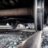
I have a +5% grade coming up from my lower level, hidden staging yard (yes, I know, that's stupid-steep) and while I can easily pull several of my pre-staged trains up that hill with one traction tire equipped diesel, I need to double head anything longer than 12 cars.

I'm using Gar-Graves track for my layout and I'm happy with it overall, but I recently read where Atlas O track, with it's flat rail profile gives better traction than the slightly rounded top of Gar-Graves. That does make sense, since there is more contact area between the wheels and a flat railhead, but I'm wondering just how MUCH difference it would make? Enough for me to re-track my grade with Atlas O track?

Anyone have an opinion, or heaven forbid, actual experience with this situation?

Original Post

Replies sorted oldest to newest

I have wondered about this as well.   The first question that comes to mind is "what is the actual angle of the loco wheels?" to the rail.  Are they actually flat/horizontal to the  rail?   Some older locos have a slight camber, along the lines of the "fast angle wheel" design that helps to center rolling stock on the rails.   If locos have an angle to their wheel, then a flat top will not maximize surface contact, a matching tilt/camber to the rail head would.   

On my MTH RailKing SD70 the loco wheels appear to be exactly horizontal or flat to the rail (as far as my eyes can tell), so a flat top would maximize surface contact area for this loco.  

My LionChief GP also seems to have drivers that are horizontal to the rail.   

If this is the norm, then yes a flat rail top will maximize surface area, and will be one factor in maximizing traction.

The number of traction tires on a loco likely outweighs the effect from a flat railhead.   Also assuming that magnatraction is not involved, which would make the composition of the rail itself an important factor.

You might try an experiment yourself with your locos with a 40" section of straight Atlas track tilted up at an angle, and measure the tractive effort at the coupler, and compare with your current track at the same angle.   If the traction effect is significant, you will be able to tell the difference without complicated devises to measure the force.   

Perhaps someone will have some data to share, this is an interesting question to me.   My next layout may have a 3% grade on a curve.

I'm not sure if the change in 'contact patch' would be enough to matter in this case, but it's worth checking as Ken suggested.  I would also wonder if any added resistance from the wheels of each car would cancel out the greater tractive effort.  I suppose that depends on if those wheels are flat or fast-angle.  

Interesting enough the purpose of angled wheels has little to do with resistance or centering, and more to do with allowing wheels locked to an axle to take a corner.  

May want to skip the first 45 seconds.

https://www.youtube.com/watch?v=agd8B-31bjE

JGL

YES! A great video - Thank You!

I did not know that the rails were tilted inwards as the video shows, and the reason for them being so makes sense.

Are the rails in the U.S. tilted as depicted in the video, and if so, at what angle? How is this achieved?

The slightly conical shape of the wheels to handle the curves also is interesting and rather clearly illustrated.

Alex

JohnGaltLine posted:


Interesting enough the purpose of angled wheels has little to do with resistance or centering, and more to do with allowing wheels locked to an axle to take a corner.  


I'll leave the turning to the experts, but its been mentioned that the tapered wheelsets on ralicars and locomotives is to keep the equipment centered on the rails so the flanges aren't constantly grinding on one side or the other.

This makes perfect since as a 100 car train  400 flanges grinding would be deafening along with wearing out rail much faster.


Last edited by RickO

I think the slight tapered shape does help keep things centered, but I have to wonder how effective that is on any sort of turn where the force of many tons of rail car is want to keep moving in a straight line.  

As for the tilted rails in the video, I believe that clip was from a russian subway line that uses such rails. I think that some rails for high speed trains in Europe and Japan use a similar system.  I don't think it ends up making much of a difference at 'normal' speeds.  

I don't actually think any of the effects of tapered wheels are significant on our models, but I don't know that for sure.  Mostly just breeze shooting at this point, I'm no expert on wheel geometry.  


On the original question with the steep grade, I also had an odd thought.  What about fixing a few rare-earth magnets on the bottom of the engine to help pull it down against the track.  I'm unsure of the magnetic properties of the track in use, but one could place a thin sheet of steel under the track for the length if that was an issue.  I have no idea if this would actually help or not, but I have seen folks using this sort of magnet to run trains upside down.  

JGL

In May of 2015 I starting converting my steam engines (RailKing 0-6-0, 2-8-0, Weaver 4-6-0, Williams brass 2-8-2, 4-6-2, and 4-8-4) to 2-rail Battery-Powered, Remote-Control, removed the middle rollers from the engines and the middle rail from my Gargraves and RCS track, with mainly 072 curves.  It may be nothing  more than my engines being a bit lighter now without all the stuff I removed making the conversion (I have bags of parts from each engine containing the PS2 electronics and hardware that was removed).

What I'm seeing is (at fairly slow speeds, under 20mph) the engines slow down just a tad when entering the curves, I have to keep my hand on the throttle as it were to keep them from slowing down (just like a real engine I would think).  I didn't see this as much when running them 3-rail under PS2/DCS, because of the cruise control built into the system.

From what I can tell all the engines have fairly flat tread on the wheels, so it has to be friction between the wheels and the rail as the engine goes thru the curves.

I don't think it would be worth the effort/expense to replace GG and RCS track with Atlas for negligible results, especially with a 5% grade.  Double-heading would make more sense, or shorter trains.

Last edited by Bob Delbridge
Ingeniero No1 posted:


Are the rails in the U.S. tilted as depicted in the video, and if so, at what angle? How is this achieved?

Yes, rails in the U.S. are tilted inwards.  For newer concrete ties, the inward cant is cast into the tie surface.  For traditional wood ties, the cant is part of the tie plate casting.  In both cases, the angle is 1:40.

Tie plate diagram

Concrete tie diagram

Jim

Last edited by big train

Excellent explanation video!  When I first began looking at it, I was disappointed thinking it was going to be in a foreign language.  But the drawings and animation are completely self explanatory and no verbiage is needed.  As to the "tipped" rails, I'm not aware that this practice ever became used in America.  Anyone know for sure? 

And, in modeling, does anyone know, for sure, the comparison between rail-head shapes?  Our stuff runs from the complete round, or tubular, through the relative flat surface of Gargraves track to what appears to be completely flat top rails of Atlas track.  Also, does anyone have information on the coefficient of wheels to track surface comparison of plated steel rail, stainless steel rail or nickel silver?


Paul Fischer

big train posted:
Ingeniero No1 posted:


Are the rails in the U.S. tilted as depicted in the video, and if so, at what angle? How is this achieved?

Yes, rails in the U.S. are tilted inwards.  For newer concrete ties, the inward cant is cast into the tie surface.  For traditional wood ties, the cant is part of the tie plate casting.  In both cases, the angle is 1:40.

Tie plate diagram

Concrete tie diagram

Jim

Jim,

Thank you for your reply and for the diagrams - they make everything clear.

Alex

richtrow posted:

"That does make sense, since there is more contact area between the wheels and a flat railhead, but I'm wondering just how MUCH difference it would make? "

I guess a question would be with flat rail and rubber tires is it possible the wheel would touch the rail head and the rubber tire not be in contact making your situation worse? Not sure the effort and expense would give you much improvement in pulling power with that grade even if it works better.

Just think of the wonderful operational opportunities you have with built in double heading right now!

Last edited by BobbyD
BobbyD posted:
... Just think of the wonderful operational opportunities you have with built in double heading right now!
 

Thanks for all your input guys. I appreciate it.

Bobby, while can see the "wonderful operating opportunities" angle, my wallet and savings account just see "You need to buy 5 to 8 more locomotives" And when you model a very specific period of time, place and railroad, that starts to get very difficult really quick!

Still not sure I what I want to do.  I'd hate to rebuild that section, with expensive Atlas O flex track, and not gain any significant benefits.

Ken-Oscale posted:

... The number of traction tires on a loco likely outweighs the effect from a flat railhead.   

... Perhaps someone will have some data to share, this is an interesting question to me.   My next layout may have a 3% grade on a curve.

My Atlas O SD40 is the best puller I own. It has 8 traction tire instead of the regular 4.  The inside wheels, next to the fuel tank have tires as usual, but the blind center wheels also have tires.

That thing pulls every train I have up that grade. I'm just concern that putting that kind of stress on a locomotive on a regular basis will hurt the motors in the long run.

As for your proposed 3% curved grade. All I can say is, based on my experience, that unless you're running a really long train (+25 cars), with our modern, dual can motored, traction tire equipped locomotives it shouldn't be a problem whatsoever. 

A couple of other things to consider...

  • The rounded rail profile reduces the contact surface area increasing the pressure on the traction tires. This might increase the traction.
  • Your track may need a good cleaning.
  • Adding weight to your engine should improve your tractive effort.
  • Depending on your rail material, magnetraction may not work. The experienced modelers can tell you which track is/is not magnetic.
JohnGaltLine posted:

I think the slight tapered shape does help keep things centered, but I have to wonder how effective that is on any sort of turn where the force of many tons of rail car is want to keep moving in a straight line.  

As for the tilted rails in the video, I believe that clip was from a russian subway line that uses such rails. I think that some rails for high speed trains in Europe and Japan use a similar system.  I don't think it ends up making much of a difference at 'normal' speeds.  

I don't actually think any of the effects of tapered wheels are significant on our models, but I don't know that for sure.  Mostly just breeze shooting at this point, I'm no expert on wheel geometry.  


On the original question with the steep grade, I also had an odd thought.  What about fixing a few rare-earth magnets on the bottom of the engine to help pull it down against the track.  I'm unsure of the magnetic properties of the track in use, but one could place a thin sheet of steel under the track for the length if that was an issue.  I have no idea if this would actually help or not, but I have seen folks using this sort of magnet to run trains upside down.  

JGL

You would actually increase the drag on the loco.  

RickO posted:
JohnGaltLine posted:


Interesting enough the purpose of angled wheels has little to do with resistance or centering, and more to do with allowing wheels locked to an axle to take a corner.  


I'll leave the turning to the experts, but its been mentioned that the tapered wheelsets on ralicars and locomotives is to keep the equipment centered on the rails so the flanges aren't constantly grinding on one side or the other.

This makes perfect since as a 100 car train  400 flanges grinding would be deafening along with wearing out rail much faster.


Wouldn't that be 800 flanges.....LOL


A long time ago it was thought that the limited contact of steel wheels on steel rail would not result in any pulling power at all.

I don't know anything about rubber tires on model trains, but I do know that the kind of steel has a lot to do with traction.  I have a 4-4-2 with cast iron driver tires, and it will outpull a 2-10-2 with plated driver tires.  

I have heard that sprung drivers will give more traction.  The above 4-4-2 has rigid drivers.  It pulls just as well as my fully sprung locomotives with cast iron tires.

DP posted:


Wouldn't that be 800 flanges.....LOL


Well no, my point was that since the rail guage is slightly wider than the flanges in order for the whole "centering wheel taper" thing to work.

That if the wheels were flat it would allow the wheels to shift back and forth causing squealling on one side or the other, i.e. 4 wheels on each 8 wheeled freight car.

For all of the wheels to be grinding thier flanges the rail guage would have to be incorrect/too narrow and the tapered wheels/ centering wouldn't make a difference anyway.

Attachments

Images (1)
  • blobid0

Just about all hi-rail locomotives now have traction tires (which is one of the reasons I went to scale wheels/fixed pilots). The plated wheels on my scale-wheeled engines seem to do pretty well with freight hauls (generally scale wheeled as well). I do get slippage in an area of the club layout that has a curve on grade with a couple of passenger engines, but I think that can be attributed to the weight and rolling resistance of the hi-rail MTH passenger cars.

I think Bob has nailed it with respect to the materials used for the driving wheels. I had a Williams SD45 that didn't have traction tires, but had sintered iron wheels and that pulled very well, even on tubular "round-top" rail.

The big thing that will help pulling power is adding weight to the locomotive, but that also increases load on the motors and current draw. When P&D was selling their F-unit kits, they recommended ballasting the locomotives to about 8 pounds total engine weight, but had the caveat about the additional load on the motor.

RickO posted:
DP posted:


Wouldn't that be 800 flanges.....LOL


Well no, my point was that since the rail guage is slightly wider than the flanges in order for the whole "centering wheel taper" thing to work.

That if the wheels were flat it would allow the wheels to shift back and forth causing squealling on one side or the other, i.e. 4 wheels on each 8 wheeled freight car.

For all of the wheels to be grinding thier flanges the rail guage would have to be incorrect/too narrow and the tapered wheels/ centering wouldn't make a difference anyway.

Yes, you did say "Flanges".  I should have read your words more carefully.

Last edited by Former Member

LGB and some other G scale manufacturers, make ball bearing wheel sets for rolling stock.  Each wheel spins freely of it's opposite on the axle.  The drag is greatly reduced.  I don't know if any O scale wheels are of this type, but it would be interesting to know how they perform if indeed they are available in O scale.

I tried to use scale wheels on the Ross track. While they worked fine on the everything but the switches, they didn't do so well on Ross switches. The frogs and guide rails are just too wide and deep so the scale wheel kind of wanders through the switch and sometimes derails. My idea was to buy MTH diesels with scale pilots and wheels and then change out the scale wheels for hi-rail ones. With minimum curves of O-80 I can get by without the swinging pilots. I got a beautiful SD70Ace in the Southern Pacific Legacy scheme, but the engine had several manufacturing defects that I turned it back to the store and traded up for my A-B-B-A N-S F7 lash up. I'm not unhappy about that decision, but I'd still like some engines with fixed pilots.

Yeah, there were two rail wheelsets with ball bearings.  Did not become very popular, and now they are a curiosity.  Of interest - Bob Heil says that Sunset can install them on axle ends for about 40 cents per axle, and is doing that on some new imports.  I can see the advantage on cars, but I doubt they will help a locomotive.

Matt - when you wear the plating off the Sunset steamers, their pulling capability dramatically increases.  The plating is for appearance and corrosion protection, but is a net negative for performance.

Add Reply

Post

OGR Publishing, Inc., 1310 Eastside Centre Ct, Suite 6, Mountain Home, AR 72653
800-980-OGRR (6477)
www.ogaugerr.com

×
×
×
×
Link copied to your clipboard.
×
×