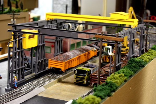
I build two basic styles of gantry cranes. One has both sides moving on track with the crane way stationary. The other has both sides stationary with the crane way moving back and forth. This particular build will be the later type. Once completed it will look something like below except this time I will attempt to place the control booth with the crane way so both can travel together.


IMG_0860-01

The first sub-assembly to build are the side supports. A glue jig is a necessity to make all sides supports the same.

IMG_3054

The two inner vertical members are H-8 columns cut to 7.5 inches. The angled supports are B-8 beams cut to fit. A-6 angles are glued to the four supports to hold them in place.

IMG_3055

Once dry enough to lift off the jig additional B-8 beams are glued in place.

IMG_3056

The side support sub-assembly is then turned around and A-6 angles are glued to the opposite side (aligned by eye).

IMG_3058

60 mil thick styrene stock is cut to ½ inch wide by 3 ¾ inch long and glued to the support legs. The side support sub-assembly is now complete. Five more will be necessary.

Attachments

Images (5)
  • IMG_0860-01
  • IMG_3054
  • IMG_3055
  • IMG_3056
  • IMG_3058
Last edited by Joe Fauty
Original Post

Replies sorted oldest to newest

The main beam assembly for the gantry crane is made using I-Beam B-36. I glued a B-8 I-beam into an C-12 channel then glued this to the top of the B-36. This will be the run way rail for the crane assembly. I sanded the bottom of the B-36 flat so it would glue to the A-4 on the side support. I also glued a spacer onto the main beam so that I could get more glue surface for the side support.

IMG_3066

The C-12 channel on top of the side support is just to hide the top area where the four posts meet. I glued CFS-4 white styrene channels onto the B-36 to make the main beam look like a girder plate.

Gantry Crane [3)

Gantry Crane [1)

This is side view of the main beam assembly showing the side support leg glued in place. At the top is the B-8 / C-12 assembly then the main beam(B-36). The white styrene is the CFS-4 channel. The spacer between the main beam and the side support is an H-8 column.

This is the completed main beam / side support assembly.

IMG_3065

Attachments

Images (4)
  • IMG_3066
  • Gantry Crane (3)
  • Gantry Crane (1)
  • IMG_3065

Joe,

I am a retired mechanical engineer who designed and performed design analysis calculations for bay cranes in tonnages from 50 to 350 tons from the late 1970's through the mid 1980's. The bay cranes we designed and built had triaxial motion. For reference , the bridge structure and drive equipment moves in the x-direction, the trolley and its drives moves in the y-direction(90 degrees to the x-direction) and the hoist in the z-direction( 90 degrees to the x-y plane of the trolley and bridge). The runway structure that you designed and build including the sway bracing is well conceived. I have built many of the Plastruct O Scale kits including the oil refinery  and purchased component shapes(ABS or styrene) other structures or roof trusses for my IHC enginehouses. The oil refinery is very detailed and one must be able to read a print to build this kit, once completed, it adds a new detail to the layout. The bay crane seams to be the HO Cornerstone bridge crane kit. This is a good example where an HO structure can used on a O Scale or 3-Rail layout.


IMG_3072

The motor assembly comes next. The motor assembly consists of two plates of 80 mil white styrene. One plate is about 1/8 inch wider than the other. This ledge will fit into a H-6 column that will act as a rail runner on the girder beam assembly. There are two TB-8 tubes on both ends. Theses act simply as bracing. The two TB-12 tubes on the inside will be used to roll the hoist up and down. The back tube as the two TB-8’s are glued to the side plates. The TB-12 with the TB-4 sticking out is a loose fit that can rotate.

IMG_3069

The TB-8 tubing have small pieces of TB-4 inserted as shown above. The same applies to the two TB-12 except one end of on tube has an extended length of TB-4.

IMG_3070

Holes are drilled into the inside plate and one hole is drilled on one of the outside plates. The tubing is fitted into one inside plate then the other inside plate is attached on the opposite side. Finally the outside plates are fitted and glued in place. Be careful not to get glue around the TB-12 that needs to rotate.

IMG_3073

IMG_3074

The motor housing is built with 80 mil styrene sides and 40 mil roof laminated with corrugated siding. In the bottom figure you can see the motor housing sitting in the H-6 runners. If the housing is a tight enough fit it can be fitted over the motor assembly without glue. In this case it was a little too wide so spacers had to be added and the housing glued onto the motor assembly. This won’t matter when it comes time to attach the hoist with threading.

Attachments

Images (5)
  • IMG_3072
  • IMG_3069
  • IMG_3070
  • IMG_3073
  • IMG_3074

I used a OWTA 24 truss member with C-16 end caps in the front and back of the gantry crane superstructure. These are the only hard glued sections holding the gantry together so the customer will need to glue the supports to his table.

Gantry Crabne 7 [3)

Gantry Crabne 7 [4)

Next was the bridge girder and end trucks. The bridge girder is a piece of BFS-20 I-beam with a H-6 column glued on top as a runner for the motor assembly. I glued sections of C-16 as glue bases for the end trucks but later cut them a lot shorter. I still need to add C-6 as stiffeners to one side of each bridge girder.

Gantry Crabne 7 [2)

I deviated from my plans and built the end trucks differently this time. I glued four sets of two WH-20 wheels together and sandwiched them between two C-12 channels. The wheels will not spin however they glide smoothly in the runway track. Next gantry crane I am going to extend the end trucks past the girder beams and place the wheels on the outside of the beams. This will look more realistic and add more stability to the girder beam assembly. I am going to try gluing the end truck to the girder beam as shown below or glue the girder beam to the top of the end truck. Not sure which as yet.

Gantry Crabne 7 [7)

A couple of photos of the almost complete gantry crane.

Gantry Crabne 7 [5)

Gantry Crabne 7 [6)

Attachments

Images (7)
  • Gantry Crabne 7 (3)
  • mceclip0
  • Gantry Crane 7 (4)
  • Gantry Crane 7 (2)
  • Gantry Crane 7 (7)
  • Gantry Crane 7 (5)
  • Gantry Crane 7 (6)

Joe, your cranes are fantastic. Thank you very much for the step by step instructions with photo's. I hope to to make one in the fall.

Coach Joe you can save this thread to PDF file. Go up to your browser menu, select File, then select Print, in the Print menu there will be a destination or other print option, from there select PDF and follow the prompts to where you want to save it.

-Tom

The control booth is basically a 2 inch square box. I used 40 mil thick styrene laminated with Plastic corrugated siding. The railing is HR-8. I added a small control booth to the inside and made the door a sliding style as shown in the next photo.

IMG_3096

IMG_3094

I decided to attach the control to the super structure so mad a small platform from 40 mil sheet stock and glued it to the side assembly. The gantry crane is basically ready for paint. The customer wants dark gray. After painting I will attach the cable hook.

IMG_3097

IMG_3098

YCC Block 001

Attachments

Images (5)
  • IMG_3096
  • IMG_3094
  • IMG_3097
  • IMG_3098
  • YCC Block 001
John Ochab posted:

Joe,

Thanks for posting the fabrication of the bay crane, one question, how did you fabricate the hook block and what did you use for the hook.

John


John:

The hook is made by Conrad/NZG. It is the YCC or NZG 202 single sheave version. An example is https://jlcranes.com/product/h...v-redwhite-41-ton-2/          or http://www.dhsdiecast.com/Hook-Block-1-Shiv-Red_White-41-ton/productinfo/YCC202/ This stuff is popular so is out of stock a lot. When I get lucky I will order 5 at a time.

Last edited by Joe Fauty

Add Reply

Post

OGR Publishing, Inc., 1310 Eastside Centre Ct, Suite 6, Mountain Home, AR 72653
800-980-OGRR (6477)
www.ogaugerr.com

×
×
×
×
Link copied to your clipboard.
×
×