
Hi,


I am starting to set up my track using Gargraves for the first time and I am having trouble getting power to the manual Hand throw switches. The train goes into the switch and stops.  Is there a special way to wire these to carry the power or should I have installed insulated pins in them like the old o 27 switches from Lionel? Any help would be great.


Thanks!!!


Jim

Original Post

Replies sorted oldest to newest

Not sure what you mean by reference to something that slides into the track connections.  Under the switch, just locate the clips that hold the center rail.  I am assuming that your situation is that power is not getting past the switch.  If a loco stalls on the switch and if nudged past the switch, then there could be a different problem.

Originally Posted by JimmyG:

So I am putting a jumper wire at all three center rails of the switch? I guess that I can use the ones that slide into the track connections as the pins. Correct?


Thanks for your help!


Jim

 Correct. To my knowledge, GarGraves never passed center rail power through their switches. 

Last edited by DennisB

My GarGraves switches are over 30 years old and there are no connections and there never were from the beginning in the 1950s. Your under switch connections must have only been produced for a short period. I've never seen it.


Having said that, I just got off the phone with GarGraves and they did offer through wiring for a very short period. It was discontinued because of the possibility of too much current in the wire causing a melt down of the switch.

Last edited by DennisB

I have Gargraves switches and the ones that don't have the power for the center rail all the way through are the 072 switches, the power stops at the switch input side.


The 042 switches I have all the center rail power goes through them.


One other note about using Gargraves switches; if you put two switches back to back(curved piece to curved piece) be careful as you may lose the common or outside rail power because of the plastic in the switch. A very easy way to solve that is to put a one to two inch piece of straight track between the two switches and power all the outside rails.


Lee Fritz

Last edited by phillyreading

Lee, your last point is very important.  Such dead spots sneak up on you, and often only show themselves when you're deadheading a short loco.  I solder a jumper wire from the through rails of one switch to the through rails of then other, as well as having ground drops on all 3 blocks.  Careful as I thought I've been, years after building the layout a deadheading Docksider caught a couple of dead spots.


As I thinnk back, I seem to recall that the Gargraves switches with the connectors were their 100" switch.  If I remember, I'll stop by their booth at York and ask.  The gentleman who mans the booth is very helpful is resolving any issues with Gargraves products.

Gargraves discontinued connectivity between the center rails across the switch about 10 years ago. Before that they were connected with a wire below the switch for a number of years.  Apparently Gargraves thought that in the event of a derailing short the connecting wire below would heat up, melt the plastic and/or cause a fire. I think that this is a really unusual concern. If they had an issue all they should have done is use heavier gauge wire. 
By no longer connecting the center rails for each side of the switch, it is just another reason why I will not use their switches. I can do without the extra work of connecting each side of the switch, by first drilling holes, cleaning, soldering on each side and running wire. Its now Ross switches 100%  

Some notes on this discussion.

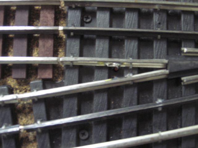
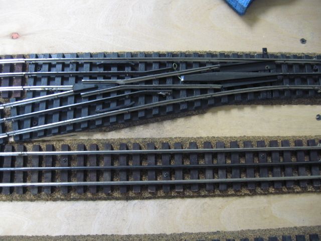
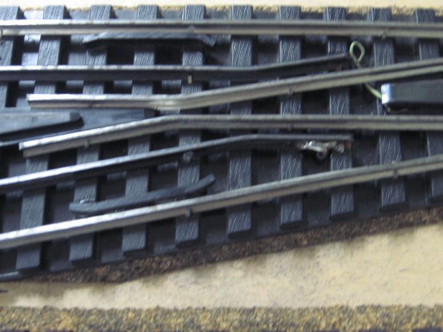
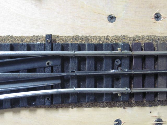
This is a used Gargraves switch there are (3) black rail center pieces that are not wired together.  Upper left, Lower left and center right.  The switch is a used switch and a small piece of green wire was added, center of picture, to connect center rail pieces

Power was added upper left.  Note the solder connection on the section of track, to the left, connected to the switch.


 Power was added lower left. Note the solder connection to the switch black center rail near the frog.

Center right connection. Near the track screw in the switch.

Ross Switches, that are not "Ross Ready", would require the same connections. 


Also note that to do automatic, electric, non-derail switch motor wiring. (2) additional wires are added at the short, (isolated rail pieces near the switch frog). Plastic isolation pins were added at these outside rail connections.


Last edited by Mike CT

Mike, FYI, I have one switch where the non derailing section is in the short piece by the frog.  There is at least one bit of rolling stock or a loco that, when it goes in the other direction and passes that section, occasionally triggers the non-derailing and causes chatter.  Apparently it has a wide wheel tread.  I do note that, if one uses the other rail, it's easy to break ground continuity through the rail.


As I've said before, if you are wiring a conventional layout for maximum operating flexibility, or a DCS layout with the ability to kill areas, switches are the ideal place to separate blocks.  For this the current Gargraves setup is ideal.  But making or breaking a connection under the switch is so easy it has never been a consideration for me in selecting a switch.  Of course, "It's your layout and you should set it up the wau you want it."

Last edited by RJR

Add Reply

Post

OGR Publishing, Inc., 1310 Eastside Centre Ct, Suite 6, Mountain Home, AR 72653
800-980-OGRR (6477)
www.ogaugerr.com

×
×
×
×
Link copied to your clipboard.
×
×